
Subscribe to Our Youtube Channel
Related Manuals for Lissmac FBM 300 P


Summary of Contents for Lissmac FBM 300 P
- Page 1 OPERATING MANUAL JOINT BRUSHING MACHINE FBM 300 P FBM 300 D LISSMAC Maschinenbau GmbH Lanzstrasse 4 D-88410 Bad Wurzach Tel. +49 (0) 7564 / 307 – 0 Fax +49 (0) 7564 / 307 – 500 lissmac@lissmac.com www.lissmac.com 1/42...
- Page 2 2/42...
- Page 3 Imprint The operating manual is valid for:LISSMAC Joint Brushing Machine FBM 300 P FBM 300 D Company headquarters: LISSMAC Maschinenbau GmbH Lanzstraße 4 D - 88410 Bad Wurzach Phone: +49 (0) 7564 / 307 – 0 Fax: +49 (0) 7564 / 307 – 500 lissmac@lissmac.com...
- Page 4 BASIC SAFETY INSTRUCTIONS Warning notices and symbols in this operating manual SIGNAL WORD Type and source of danger Consequences of non-compliance Actions to avert the danger. The signal word under the danger symbol indicates the degree of danger: DANGER This signal word signifies an extremely dangerous situation.
- Page 5 Warning and safety labels The following warning and safety symbols were attached on the machine: Observe operating manual! Wear hearing protection and safety glasses Wear face protection This symbol warns of a rotating tool This symbol warns of residual risk when handling the machine This symbol indicates the attachment point for crane transport This symbol indicates a projected objects hazard This symbol indicates the noise power level of the machine...
- Page 6 Additional documentation of the respective manufacturers of individual components of the machine are available as supplements to this operating manual: Operating manual petrol motor LISSMAC assumes no responsibility or liability for the completeness of any additional documents. Changes and reservations We attempt for this operating manual to be correct and up-to-date.
- Page 7 Notes: 7/42...
-
Page 8: Table Of Contents
1. Features & Benefits ......................9 Table of Contents 1.1. Basics of intended use ....................10 1.2. Organisational measures ....................10 1.3. Personnel choice and personnel qualification; basic responsibilities ......11 1.4. Safety instructions for operation phases ................ 12 1.4.1. Transport, assembly and installation ..............12 1.4.2. -
Page 9: Table Of Contents 1. Features & Benefits
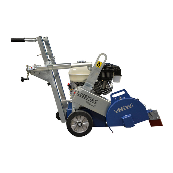
1. FEATURES & BENEFITS The FBM 300 joint brushing machine is optimally designed for removing problem substances from the already cut joint. The direction of rotation of the brush is opposite to the direction of movement so dirt is not guided back into the already cleaned joint. ... -
Page 10: Basics Of Intended Use
1.1. Basics of intended use The warranty obligation of the manufacturer and supplier is voided for improper or non-intended use. Any change to the machine which is not carried out by the manufacturer is prohibited. Changes, removal or addition of parts to the machine only with the written approval of the manufacturer. The machine is constructed according to the state of the art and recognised technical safety rules. -
Page 11: Personnel Choice And Personnel Qualification; Basic Responsibilities
Use personal protection equipment if necessary or required by regulations! Observe all safety instructions and danger warnings of the machine and keep them in legible condition! Replace safety and danger instructions that are damaged or non-readable any more. For safety-related changes to the machine or its running behaviour, stop the machine immediately and mark it accordingly. -
Page 12: Safety Instructions For Operation Phases
1.4. Safety instructions for operation phases 1.4.1. Transport, assembly and installation Transport, assembly and installation on/with the machine may only be carried out in transport position. Secure the machine against rolling away. Transport, assembly and installation on/with the machine may only be carried out with removed tool and when the petrol motor is turned off. -
Page 13: Operation
1.4.3. Operation Refrain from working in any manner that is questionable in regard to safety! Take measures to ensure that the machine is operated only in a safe, functional condition! At least once per shift check the machine for externally recognisable damage and deficiencies! Any changes which occur (including operating behaviour) must be reported immediately to the responsible post/person! If necessary, immediately stop the machine and secure it against restart! Immediately stop and secure the machine in case of malfunctions! Immediately correct malfunctions! Electrical... -
Page 14: Special Work While Using The Machine
1.4.6. Special work while using the machine Follow all setup, maintenance, and inspection activities and schedules prescribed by the operating manual, including all information about the replacement of parts / assemblies! These activities may only be carried out by technical personnel. Inform operating personnel before beginning special and maintenance work! Name a supervisor! If the machine is turned off during maintenance and repair work, it must be secured against unexpected application of power. -
Page 15: Dust
1.5.3. Dust When working in close quarters, follow any applicable national guidelines! 1.5.4. Noise See 2.4 Noise power level of the machine 1.6. Transport To implement using a crane, slinging equipment with sufficient load carrying capacity must be used. Slinging equipment must be checked for damage before use. -
Page 16: Packaging And Storage
1.7. Packaging and Storage To ensure sufficient protection during shipping and transport, the machine and its components are carefully packaged. When receiving the machine, the machine should be checked for damage. The packaging of the device consists of materials which can be recycled. Put these by type into the relevant recycling containers, so that they can be recycled properly. -
Page 17: Description Of The Device
2. DESCRIPTION OF THE DEVICE 2.1. Name of machine parts Pos. 1 Handle Pos. 6 Brush protective hood Pos. 2 On-board tool Pos. 7 Parking brake Pos. 3 Crane eye Pos. 8 Stop (lifting point for crane transport) Pos. 4 Petrol motor Pos. -
Page 18: Technical Data
2.3. Technical data FBM 300 P FBM 300 D Brush width 8-18 mm Brush depth 60 mm Brush-Ø 300 mm Fixture 20,0 mm (25,4 mm) Drive motor 1-cylinder Honda 1-cylinder Hatz Fuel Petrol Diesel Output power max. 8,7 kW / 11,7 PS... -
Page 19: Hand Arm Vibration
The given value was determined with a maximum tool diameter of 300 mm. The impact can be reversely proportional to the weight of the operator. Total vibration value: FBM 300 P a 8,99 m/s FBM 300 D a 13,26 m/s The following standards were complied with during measurement: EN ISO 5349, VD 2057 Sheet 2, Directive 2002/42/EC. -
Page 20: Commissioning
3. COMMISSIONING 3.1. Connections and operating materials Operating motor oil The motors are filled with motor oil by the manufacturer. Only motor oil approved by the manufacturer may be used. The details and the quality requirements are contained in the operating manual of the fuel motor Fuel The machine must be selectively filled with petrol or diesel depending on the design. -
Page 21: Filling The Fuel Tank
3.3. Filling the fuel tank WARNING Risk of fire due to ignition sources When filling, the combustion motor consists of highly flammable fuel fumes. All ignition sources must be kept away Smoking absolutely prohibited during this process CAUTION Risk of burning on hot motor parts Bodily contact when filling the machine. -
Page 22: Parking Brake
3.4. Parking brake CAUTION Risk of injury due to accidental rolling away Accidental rolling away can injure persons and damage the machine and other objects. Use the parking brake of the machine every time it is turned off or work is interrupted ... -
Page 23: Tool Change
3.5. Tool change WARNING Risk of injury on the rotating tool Heavy abrasion due to contact with the tool can result. Do not open or remove the brush protective hood during operation Do not reach into the rotating tool ... -
Page 24: Drive Belt
3.6. Drive belt WARNING Risk of injury on the rotating tool Heavy abrasion due to contact with the tool can result. Do not open or remove the brush protective hood during operation Do not reach into the rotating tool ... -
Page 25: Collection Basket (Optional)
3.7. Collection basket (optional) WARNING Risk of injury on the rotating tool Heavy abrasion due to contact with the tool can result. Do not open or remove the brush protective hood during operation Do not reach into the rotating tool ... -
Page 26: Generator Kit (Optional)
3.8. Generator kit (optional) WARNING Risk of injury on the rotating tool Heavy abrasion due to contact with the tool can result. Do not open or remove the brush protective hood during operation Do not reach into the rotating tool ... -
Page 27: Transport
4. TRANSPORT 4.1. Transport position CAUTION Hazards from the machine rolling away Accidental rolling away can injure persons and damage the machine and other objects. The parking brake of the machine must be used When transporting the machine, unintentional position changes must be prevented. Motor oil can leak into the combustion area and damage the petrol motor. -
Page 28: Transport By Crane
4.2. Transport by crane WARNING Suspended loads Injury due to falling parts or the machine. Do not step under the suspended machine Only use undamaged lifting gear and loading equipment with sufficient lifting capacity and length The machine may only be transported or moved in transport position. ... -
Page 29: Operation
5. OPERATION 5.1. Safety WARNING Risk of injury on the rotating tool Heavy abrasion due to contact with the tool can result. Do not open or remove the brush protective hood during operation. Do not reach into the rotating tool. ... -
Page 30: Working With The Machine
5.3. Working with the machine WARNING Risk of injury on the rotating tool Heavy abrasion due to contact with the tool can result. Do not open or remove the brush protective hood during operation Do not reach into the rotating tool ... -
Page 31: Maintenance
6. MAINTENANCE 6.1. Service WARNING Risk from unqualified personnel Performing service, repair and maintenance work by unqualified and unauthorised personnel can lead to serious or fatal injury The machine must be secured against restarting by other people. Cleaning To protect painted surfaces no aggressive cleaning agents may be used. -
Page 32: Troubleshooting Table
6.2. Troubleshooting table WARNING Risk from unqualified personnel Performing service, repair and maintenance work by unqualified and unauthorised personnel can lead to serious or fatal injury The machine must be secured against restarting by other people. Error Cause Remedy Low power V-belt slips... -
Page 33: Torque Of Screw Connections
6.3. Torque of screw connections Strength class: 10.9 12.9 Dimensions Max. tightening torque in Nm Max. tightening torque in Nm Max. tightening torque in Nm 11,2 11,3 16,5 19,3 27,3 40,1 46,9 1057 1136 1329 1176 1674 1959 1597 2274 2662 33/42... -
Page 34: Maintenance Plan
6.4. Maintenance plan NOTICE This section should be used as a proof of already performed maintenance and as a service book. All warranty and service work must be entered as proof. Machine/type: Serial number/year of manufacture: Date Performed maintenance or service works Date/signature 34/42... -
Page 35: Warranty
7. WARRANTY The warranty for this machine is 12 months. For the following listed wear parts the warranty only applies if the wear is not caused by operation. Wear parts are parts that with intended use of the machine have limited operational wear. The wear time is not uniformly specified, it differs according to intensity of use. -
Page 36: Replacement Parts
8. REPLACEMENT PARTS Spare part Item Item no. Designation Specification Units Recommend ation 691332 HANDLE HOLDER 280129 SLIDE STOPPER 300003 RING SCREW DIN 580 8,0 GALV. 691333 HANDLE 200985 SLIDE STOPPER 200985 SLIDE STOPPER 201822 HANDLE RUBBER 614582 COMBINATION SPANNER 681399 HAND CRANK COUPL. - Page 37 Spare part Item Item no. Designation Specification Units Recommend ation 300166 DISC M12 DIN 125 202816 SPACER SLEEVE 300398 HEXAGON HEAD SCREW M12x4 DIN 933 300166 DISC DIN 125 A 13.0 galvanised 201959 THRUST WASHER GTM -1224-015 692419 SPINDLE FIXTURE 300808 WING SCREW 615373...
- Page 38 Spare part Item Item no. Designation Specification Units Recommend ation 208052 EXHAUST PIPE WITH CLAMP 819555 STEERING WHEEL SET ATTACHMENT 1004326 GENERATOR KIT 1040256 WORKING LIGHTS LED 12V incl. plug NOTICE To prevent incorrect deliveries, when ordering spare parts, indicate the complete model designation, year of manufacture and the machine number! Technical changes may be made! We make it explicitly clear that parts not supplied by us are also not tested and released by us.
- Page 39 39/42...
- Page 40 LISSMAC Joint Brushing Machine FBM 300 P and FBM 300 D. This declaration relates exclusively to the machine in the state in which it was placed on the market, and excludes components which are added and/or operations carried out subsequently by the final user.
- Page 41 41/42...
- Page 42 42/42...
Need help?
Do you have a question about the FBM 300 P and is the answer not in the manual?
Questions and answers