
Related Manuals for Kaadas S500-C


Summary of Contents for Kaadas S500-C
- Page 1 S500-C User Manual www.kaadasgroup.com Shenzhen Kaadas Intelligent Technology Co., Ltd reserves all rights for the final interpretation to this user manual. All design and specifications are subject to change without notice.
- Page 2 Friendly reminders: Dear customers, thank you for using our smart lock. Please check the package content and read the installation instruction carefully before you install this lock, and then install the product according to the instruction. Our company will not assume any responsibility for direct or indirect product problems, other hazards and losses if you don't follow the instruction to install.
-
Page 3: Table Of Contents
Contents 4. Setup 1. Important information 5. How to use Safety instruction Before setting Unlock from outdoor Warning Enter master mode Unlock by mechanical key Disposal of used battery Change the master PIN code Lock from outdoor / lock from indoor Add user PIN code and lock / double lock from indoor... -
Page 4: Important Information
•Do not short-circuit the two poles of the battery lead with metal objects in case of explosion. •Making sure replacement or maintenance are done by professional person authorized by Kaadas. •Your warranty may invalidate if you used accessories produced by other manufacturer or not recommended by Kaadas. Disposal of used battery and lock •Please understand the local electronic product classification and collection system. -
Page 5: Installation
2. Installation Package Content This package list is for reference only, and all contents are subject to the actual products. Front panel(including Black panel(including Mechanical key Drilling template Mortise Strike plate silicone pad) silicone pad) & Key cylinder Screw pack Mounting plate User card Screw pack... -
Page 6: Exploded View
Exploded view Understanding the installation of three-dimensional assembly is benifit to know the structure of the lock. 1. Back cover 2. Mounting screw(3 pcs) 3. Back panel 4. Pressure spring(2 pcs) 5. Mounting plate 6. Square shaft(2 pcs) 7. Mortise 8. -
Page 7: Preparing For Installation
Preparing for installation Check door open direction This product fits for all door open directions Right-out/Right-in/Left-out/Left-in. Right-out Right-in Left-out Left-in... - Page 8 Change latch direction 1. Push the “bolt switcher” to the top side 2. Press in the latch bolt. Directional screw 4. Pull out the latch bolt and push 3. Please follow arrow direction to turn the “ bolt switcher”to the end. round the latch bolt 180°.
- Page 9 Change handle direction Change handle direction of front panel Screws Screws Positioning disc Positioning disc Shield sleeve Shield sleeve Cable 1. Take out the 2 screws, the positioning 2. Rotating the handle to the other end. 3. Reposition the sensor cable to the upper side, disc and the shield sleeve.
- Page 10 Change handle direction of back panel Screws Screws Positioning disc Positioning disc 1. Take out the 2 screws and the 2. Rotating the handle to the other end. 3. Put the positioning disc and shield sleeve positioning disc. back, and fasten the screws. Caution: Please choose correct screw pack according to your door thickness.
-
Page 11: Installation
Installation Connection screw bolts Connection screw bolts Indoor Square shaft Pressure spring Connecting cable for front panel Connecting cable for mortise Connection screw bolt Caution: Caution: Spring: the big end is downward. Do not make the mortise deadbolt come out. 1. - Page 12 Mounting screw Connecting cable for mortise Connecting cable for mortise Connecting cable for front panel Connecting cable for front panel 4. Pass the connection wire through the bottom bore. Then align and 5. Install the mounting plate with fixing scews tightly against the insert square shaft into mortise holes to make the front panel fit door surface to fix the front panel.
- Page 13 Mounting screw Square shaft Pressure spring Connecting cable for mortise Connecting cable for front panel Mounting screw 6. Place pressure spring and square shaft in the back panel in proper order. 7. Install the batteries and the battery cover. Then install the And insert the connecting cable of front panel into related sockets of the striker assembly to finish the installation.
-
Page 14: Overview
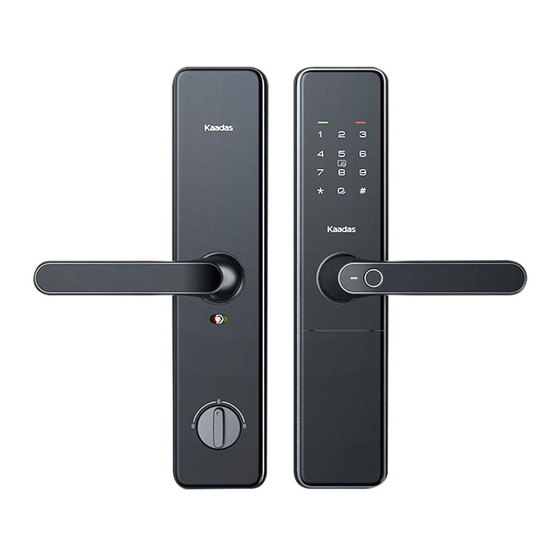
3. Overview Outside panel Inside panel Touch keypad Back cover Card reader area Reboot button Fingerprint sensor Safe handle switch Mechanical key port Reset button Manual open/close knob Emergency power port Note: This drawing is just for reference, please be subject to the actual product. -
Page 15: Setup Before Setting
4. Setup Before setting There are two modes for the smart lock-safe mode and normal mode, and the default one is normal mode. Safe mode Normal mode Have Have Master PIN code Master PIN code before entering safe mode Default master PIN code:12345678 6 groups User PIN code 10 groups... - Page 16 User number In safe mode, to delete all users is prohibited. So when you delete the single user, you can delete it according to its’ user number. You can fill the user information in below table, which is convenient for your management. Number Name PIN code...
-
Page 17: Add User Pin Code
How to enter master mode Add access date Add user PIN code Access into master mode Press [1] for user setting, then press [1] to enroll user PIN code. Enter 2 digital user number (00-09), and confirm with [#] key. Default master PIN code: 12345678 1. -
Page 18: Add User Card
Add user card Access into master mode Press [1] for user setting, then press [5] to delete user fingerprint. Press [1] to delete single user, and enter 2 digital user number (00-99) with [#] key to confirm. Voice prompt “Deletion succeeded”. Press [1] for user setting, then press [3] to enroll user card. -
Page 19: System Setting
Opening mode setting Access into master mode Press [2] for system setting, then press [2] for language setting. Press [1] for Chinese voice. Press [2] for English voice. Press [1] for user setting, then press [7] for opening mode setting. Record query Press [1] for normal mode (single verification), which means System query... - Page 20 Bluetooth setting Enable Bluetooth Access into master mode Press [5] for Bluetooth setting, then press [1] to enable Bluetooth. Caution: The default setting for Bluetooth is disable. Manage Bluetooth (under Bluetooth turned on) Access into master mode Press [5] for Bluetooth setting. Then press [1] to connect Bluetooth;...
-
Page 21: How To Use
5. How to use Unlock from outdoor Enter PIN code Fingerprint sensor Card icon area Press down the handle Press down the handle Press down the handle to open the door to open the door to open the door Outdoor Front panel Outdoor Front panel Outdoor Front panel 1.Touch keypad by palm to lighten keypad. -
Page 22: Unlock By Mechanical Key
Unlock by mechanical key First, Loose the cover of mechanical key from the position for pull, then rotate it 90 degrees.Next, insert the key into key hole and rotate it with proper angles. Mechanical key Last, press down handle to open the door Caution: Mechanical key cover In case of forgetting PIN code, battery run out or system error, mechanical key is used to open door as... -
Page 23: Other Functions
5. Other functions Safe handle feature Restore to factory default settings 1. Enable: Move the safe handle switch to display “red” mark. Once safe handle feature is enabled, the indoor handle will Safe handle switch be locked. 2. Disable: Move the safe handle switch to display “green”... -
Page 24: Replace Battery
2 groups. and other smart home interface. One group is ok for power supply, two groups is used for longer time. Please contact Kaadas distributor for more details. Network module interface Network module Back cover Caution: When battery voltage is lower than 4.8V, voice prompts “Low battery, please...
Need help?
Do you have a question about the S500-C and is the answer not in the manual?
Questions and answers