Table of Contents
Advertisement
Quick Links
Advertisement
Table of Contents

Related Manuals for Zimmer emFieldPro


Summary of Contents for Zimmer emFieldPro
- Page 1 Instructions for Use emFieldPro...
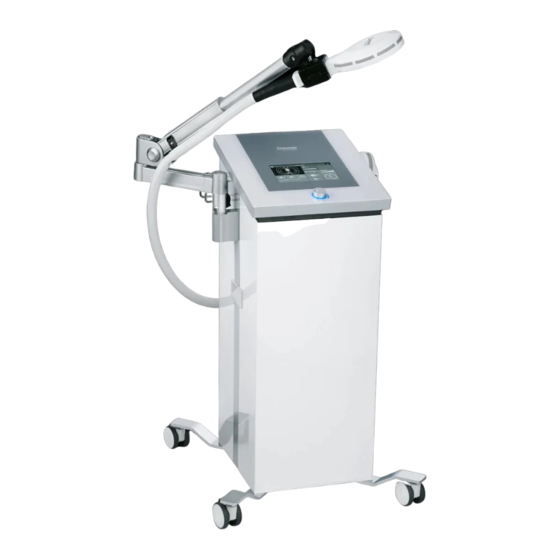
- Page 2 Illustrations Front of the Device Fig. 1 Front of the device Applicator (large) Applicator quick-connector Applicator arm Applicator (medium) Display Central control knob Control unit Swiveling wheels...
- Page 3 Illustrations Rear of the Device Fig. 2 Rear of the device Connectors for applicator tube Cooling Power connector Power switch Serial no / Identification plate...
- Page 4 Illustrations Screens and Displays Fig. 3 Screens and displays Time remaining Total operation time Configuration icon Intensity in % Start/Stop Channel selector (CH1 Large or CH2 Medium) Applied program Mode selector (Programs / Favourites / Expert mode) Program information screen...
- Page 5 Illustrations Accessories Mains cable Hex key...
- Page 6 Explanation of Symbols This symbol indicates “Danger” with regard to possible risks to people. This symbol indicates “Caution” with regard to possible material damage. Applied part BF type emFieldPro Operation instructions Follow instructions for use No access for people with pacemakers...
- Page 7 Explanation of Symbols Do not push No sitting on device The device emits energy in the form of non-ionizing electromagnetic radiation Warning, magnetic field Warning, electricity Protective earth Equipotentiality, to identify the terminals which, when connected together, bring the various parts of an equipment or of a system to the same potential, not necessarily being the earth (ground) potential, e.g.
- Page 8 Explanation of Symbols Do not stack CE marking with the number of the notified body...
- Page 9 Rear of the Device Screens and Displays Accessories Explanation of Symbols Page Indications / Contraindications Side Effects Application Information Warnings emFieldPro - in brief Intended use Device set up 6 - 7 Settings 8 - 9 Operation Instructions 10 - 18...
-
Page 10: Table Of Contents
Contents Technical Information Cleaning Disinfection CE-Mark Scope of Delivery and Accessories Device Combinations Safety and Maintenance Functional Test 25 - 26 Legal notice Error Messages / Troubleshooting 28 - 30 Disposal Manufacturer’s EMC declaration 31 - 34... - Page 11 Contents Valid for emField Pro devices. This instructions for use is an integral part of the device. It must be stored with the device and kept accessible at all times for anyone authorized to operate this device. The instructions for use is valid as of December 2021. If the instructions for use have become illegible, damaged, or are not accessible for the user for other reasons, a replacement is to be requested from the manufacturer for the safe use of emField Pro and made available to the user.
- Page 12 Be ensured that magnetic stimulation doesn’t penetrate the heart region. The emFieldPro should be used with caution in persons with Grave’s disease, active bleeding disorders or seizure disorders. Patients in the following categories cannot be treated, prior to permission of the doctor...
- Page 13 Side Effects Side effects Common side effects reported after treatment generally mild in nature. They may include but are not limited to: • Skin damage, for instance: o Local erythema o Skin redness • Abdominal discomfort, such as o Menstrual irregularities and abdominal cramping o Constipation, diarrhea, or abdominal bloating •...
- Page 14 To avoid the risk of electric shock; the device´s main plug must be disconnected from the mains supply before performing any maintenance or cleaning activities. The emFieldPro is not suitable for use in areas with an explosive, flammable or combustive environment.
- Page 15 Warnings is intended to be used exclusively for medical professionals, such emFieldPro as authorised physicians, therapists, and medical paraprofessionals. Magnetic therapy devices are not intended for use by laypersons or in home care The patient must not be left unattended during therapy.
- Page 16 Pro - in brief / Intended use What is the emFieldPro is a most reliable and powerful pulsed inductive therapy device. emFieldPro? What does the emFieldPro generates max. 3 Tesla electromagnetic field to treat acute and chronic emFieldPro do? pains. What are the Non-invasive treatment ...
- Page 17 ‘locked’ position. Note: Make sure that the emFieldPro is placed on a stable and flat surface Connect mains cable Connect the mains cable (23) to the socket on the device (11) and connect it to the mains.
- Page 18 Device Set Up After using the emFieldPro for a long time, the transducer arm may be stuck down or up. In this case, the position of the transducer arm can be changed by adjusting the gas spring pressure. To lower the arm supporter, turn the hexagonal wrench bolt in the (−) direction as shown in the figure below, and turn it in the (+) direction to lift it...
- Page 19 Once the device has been switched on and the self-test performed, the start-up screen opens. Standard screen After the self-test has been performed, the emFieldPro goes automatically in the standard screen. Selecting configuration Pressing the Configuration button (A) immediately switches to the configuration menu.
- Page 20 Settings Configuration menu (B) Brightness Adjust the brightness by using the left and right arrows. (C) Volume Adjust the volume by using left and right arrows. (D) Language Selection of the language by using the left and right arrows. (E) Admin Only for service partners (F) Version Shows information about the current software version...
- Page 21 Operation Instructions Device description The emFieldPro consists of a main body and 2 transducers connected to it. It relieves the muscular pain using electromagnetic fields. The transducer is generally placed on the area of the pain with some distance to the skin.
- Page 22 Operation Instructions Transducer placement You can adjust the position and angle of the CH1 transducer according to the patient and the stimulation area. The CH1 transducer arm can be moved up and down and left and right. The angle of the CH1 transducer can be adjusted using the transducer holder.
- Page 23 Operation Instructions (H) Time remaining (I) Total operation time (J) Configuration icon (K) Intensity in % (L) Start/Stop (M) Channel selector (CH1 Large or CH2 Medium) (N) Applied program (O) Mode selector (Programs / Favourites / Expert mode) (P) Program information screen (H) Time remaining Shows graphical the course of the treatment time.
- Page 24 Operation Instructions (M) Channel Selector Select either CH1 (Large transducer) or CH2 (Medium/Hand-held transducer). The color of the button indicates that the channel has been darkened as active. (N) Applied program By using one of the buttons (0) followed by selecting one of the stored programs by using the central control knob (6), the selected mode is displayed in the mode selection window located at the lower left part of the display.
- Page 25 Operation Instructions Change settings of the Favourites mode like following: Press the Favourites button for 2 ~ 3 seconds to set the parameters on touch screen. The user is able to set the parameter values after appearance of the parameter setting screen Choose the parameter to change.
- Page 26 Operation Instructions After pressing about 2 seconds on one of the Favourites a screen will appear in which a name of the region can be changed. After changing the name, press Exit to close the screen. Expert Mode The Expert Mode has 20 free to store modes; the user can set the parameter values directly.
- Page 27 Operation Instructions The parameter settings are: - Wave : Select one of the following waves: Sinus; Triangle; Downward Triangle; Upward Triangle or Continues by selecting the according symbol. - L (Hz) : L(ow) limit of waveform (6-149 Hz). This frequency has to be lower than H (Hz).
- Page 28 Operation Instructions By pressing on the Name for about 2 seconds, an alphabet screen appears and the pre- programmed name can be changed. By pressing the Parameter section, setting screen appears and the parameter values change. Choose the parameter to change. Wave, L (Hz), H (Hz), T1, Off, T2,, Strength, Repetition can be set in this mode by using the central control knob (6) which changes the parameter values.
- Page 29 Operation Instructions Each mode has 9 sub-modes with different parameter sets. The Expert mode operates sequentially from sub mode 1. A sub-mode is added by pressing a pencil figure at the end of the top right parameter setting screen. To remove a sub-mode, press the bin figure in the right top corner after choosing the specific sub-mode.
-
Page 30: Technical Information
Technical Information Power supply Input power: 220-240 V 50/60Hz Power consumption: max 2200VA Mains fuse T12,5 AL / 250Vac Protection class Class 1 Applied part Type BF (Applicator) Dimensions 542 (L) × 501 (W) × 993 (H) mm Weight Approx. 60 kg Operation Magnetic field strength: CH1: 3.0 T –... -
Page 31: Cleaning Disinfection
Cleaning Disinfection We recommend disinfecting at a minimum after each patient and at the end of the day and whenever there is evidence of possible contamination. Contact your health expert on this topic. Always perform cleaning prior to disinfection. Before starting any maintenance and cleaning measures the device must always be switched off at the main switch and the mains cable unplugged. -
Page 32: Ce-Mark
CE-Mark The product bears the CE-mark in accordance with the EC Directive on Medical Devices 93/42/EWG. Manufacturer Zimmer MedizinSysteme GmbH Junkersstraße 9 89231 Neu-Ulm, Germany www.zimmer.de Page 21... -
Page 33: Scope Of Delivery And Accessories
Subject to change! * Individual mains cable available. Please contact your distributor. Note: The device may be operated only with original parts from Zimmer MedizinSysteme GmbH. Otherwise, the function and safety of the patient, user and third parties cannot be guaranteed. -
Page 34: Device Combinations
Device Combinations For emFieldPro no combination devices are provided by the manufacturer. Anyone who, acting contrary to these specifications combines devices and thus operates a medical system does so at its own risk. Page 23... -
Page 35: Safety And Maintenance
Safety and Maintenance The emFieldPro is manufactured according to the safety regulations of IEC 60601-1. As manufacturer, Zimmer MedizinSysteme GmbH can only be considered responsible for the safety and reliability if: - the device is operated using a proper power outlet that is properly grounded and... -
Page 36: Functional Test
If any of the above occurs, contact your servicepartner for help. Safety inspection In order to ensure safe use, internal cleaning should be performed once per year by a person authorized by Zimmer MedizinSysteme GmbH In order to ensure safe use, be sure to check the equipment including internal components and output voltage from the person who has been given authorization from the company once per year. - Page 37 Functional Test Self-troubleshooting Symptom What to do References in the User Guide Check if the power connector of the • Chapter 6; device set up equipment is properly connected. Equipment does not turn on. Check if the power switch of equipment is •...
-
Page 38: Legal Notice
Legal Notice The emFieldPro is listed in attachment 1 of the MPBetreibV (Medical Device Operator Ordinance). Please observe the measures which are necessary as a result. In Germany, the German Social Accident Insurance (DGUV) (Regulation 3 – Electrical systems and equipment), as amended, must also be observed. -
Page 39: Error Messages Troubleshooting
Messages: Over Temperature The emFieldPro is an equipment that generates a magnetic field by applying a high current to a transducer. As heat is generated from the transducer using the high current used to create the magnetic field, cooling is performed by circulating the cooling oil inside the emFieldPro transducer. - Page 40 Disposal Transducer Error The emFieldPro always checks the connection of the transducer cable. If the cable is disconnected or damaged, the message is shown as in figure 27. In this case, equipment cannot be used anymore, and the user must contact authorized personnel of our local distributor maintenance.
- Page 41 Disposal The device may only be returned to the factory in the original packaging. It must be disposed by Zimmer MedizinSysteme GmbH. In foreign (European) countries, please refer to national regulations for disposal. Contact your distributor if necessary. Page 30...
-
Page 42: Manufacturer's Emc Declaration
The device emFieldPro does not contain any components which age over the course of the device life time and could lead to a deterioration of the electromagnetic compatibility. Thus, no maintenance is required during the life of the device to ensure basic safety. - Page 43 Table 1 Guidance and Manufacturer’s Declaration- Electromagnetic Emissions The device emFieldPro is intended for use in the electromagnetic environment specified below. The customer or user of the device emField should ensure that it is used in such environment. Emission Measurement...
- Page 44 Table 2 Guidance and Manufacturer’s Declaration- Electromagnetic Immunity The device emFieldPro is intended for use in the electromagnetic environment specified below. The customer or user of the device emField should ensure that it is used in such environment. Immunity Tests...
- Page 45 Table 3 Guidance and Manufacturer’s Declaration- Electromagnetic Immunity The device emFieldPro is intended for use in the electromagnetic environment specified below. The customer or user of the device emField should ensure that it is used in such environment. Immunity Test...
- Page 46 Manufacturer´s EMC declaration Electromagnetic immunity to HF radio communication equipment Test Maximum Immunity Test Band Distance Frequency Service Modulation Energy Level (MHz) (MHz) (V/m) 5240 5100- WLAN 802.11 a/n Pulse 5800 Modulation 5500 217 Hz 5785 Page 35...
- Page 47 Instructions for Use Zimmer MedizinSysteme GmbH Junkersstraße 9 89231 Neu-Ulm, Germany Tel. +49 7 31. 97 61-291 Fax +49 7 31. 97 61-299 export@zimmer.de www.zimmer.de...
Need help?
Do you have a question about the emFieldPro and is the answer not in the manual?
Questions and answers