Precision Digital Corporation PD6607-L2N Manuals
Manuals and User Guides for Precision Digital Corporation PD6607-L2N. We have 2 Precision Digital Corporation PD6607-L2N manuals available for free PDF download: Instruction Manual
Precision Digital Corporation PD6607-L2N Instruction Manual (50 pages)
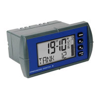
Loop-Powered Feet & Inches Meter
Brand: Precision Digital Corporation
|
Category: Measuring Instruments
|
Size: 2 MB
Table of Contents
Advertisement

Precision Digital Corporation PD6607-L2N Instruction Manual (43 pages)
Loop-Powered Feet & Inches Meter
Brand: Precision Digital Corporation
|
Category: Measuring Instruments
|
Size: 2 MB
Table of Contents
Advertisement
Related Products
- Precision Digital Corporation PD6607-LNN
- Precision Digital Corporation PD6607-L3N
- Precision Digital Corporation PD6607-L5N
- Precision Digital Corporation PD6607
- Precision Digital Corporation Loop Leader PD6602-LNN
- Precision Digital Corporation Loop Leader PD6604-L2N
- Precision Digital Corporation PD6603-L3N
- Precision Digital Corporation PD6603-L5N
- Precision Digital Corporation Loop Leader PD6604/8
- Precision Digital Corporation Loop Leader PD6603/7