Table of Contents
Advertisement
Quick Links
Advertisement
Table of Contents

Summary of Contents for PROALL G Series
- Page 1 ProAll Mobile Mixer Operator’s Manual G Model MX05001 3 March 2022 Rev.1...
- Page 2 MX05001 5810 - 47 Avenue, Olds, Alberta, Canada, T4H 1V1 E support@proallinc.com | P 403-335-9500 | F 403-335-9560 Rev. 3 March 2022...
-
Page 3: Table Of Contents
MX05001 Table of Contents Model Number ................... 1-3 Serial Number ..................1-3 Safety Decals ..................2-1 Safety Alert Symbol ................2-4 Signal Words ..................2-4 Safety ....................2-5 General Safety ..................2-5 Operating Safety ................2-6 Maintenance Safety ................2-6 Hydraulic Safety ................. - Page 4 MX05001 Step 3: Sand Weight per Count ..............5-2 Results ......................5-2 Computer Gunite Production Calibration Procedure ......5-2 Step 1: Cement Output per Auger Count ............ 5-2 Step 2: Counts per Unit Volume of Mix ............5-3 Step 3: Gate Calibration ................5-3 Fibre Feeder Calibration ..............
- Page 5 MX05001 Minimum Requirements for Replacement Oil ..........7-1 Hydraulic Oil Filter................7-2 Wear Plates ..................7-2 Service ....................7-3 Lubrication and Maintenance Points ..........7-4 Lubrication and Maintenance Frequency .......... 7-9 Electrical Distribution Box ..............7-10 Bolt Torque ..................7-11 Rev.
- Page 7 1. Introduction Congratulations, you have chosen the world’s finest and most reliable mobile mixer. You are now part of the world-wide ProAll International family, operating successfully in 36 countries. Your ProAll Mobile Mixer, manufactured by ProAll International Inc. will meet, or exceed your concrete requirements.
- Page 8 MX05001 ALWAYS give the SERIAL NUMBER when ordering Model Number: parts or requesting service or other information. Serial Number: The serial number plate is located where indicated. Please mark the number in the space provided for easy reference. Plate 1. Model and Serial Number Plate Rev.
-
Page 9: Model Number
MX05001 Model Number ##### ▪ Last 5 Digits of Serial Number ▪ 1 Standard Cement Hopper Configuration ▪ B 113 Cubic Foot (Steel) 133 Cubic Foot (Steel) Cement Hopper Size ▪ 00 No Extensions 26 in. Frame Extension ▪ G95 8.50 Cubic Meter 9.50 Cubic Meter Base Model Capacity... -
Page 11: Safety Decals
MX05001 2. Safety Safety Decals The following safety decals have been placed on Please take this manual and walk around your your machine in the areas indicated. They are machine, noting the location of the decals and intended for your personal safety and for those their significance. - Page 12 MX05001 Decal 1 Decal 2 Decal 3 Rev. 3 March 2022...
- Page 13 MX05001 Decal 4 Decal 5 Decal 7 Decal 6 Decal 8 Rev. 3 March 2022...
-
Page 14: Safety Alert Symbol
MX05001 Safety Alert Symbol This Safety Alert symbol means ATTENTION! manual. When you see this symbol, be alert to the BECOME ALERT! YOUR SAFETY IS INVOLVED! possibility of personal injury or death. Follow the instruction in the safety message. The Safety Alert symbol identifies important safety messages on the machine and in the Why is SAFETY important to you? Accidents Disable and Kill... -
Page 15: Safety
MX05001 Safety • YOU are responsible for the SAFE operation and Do not modify the equipment in any way. maintenance of your equipment. YOU must Unauthorized modifications may impair the ensure that you and anyone who is operating, function and/or safety and could affect the maintaining or working around the equipment life of the equipment. -
Page 16: Operating Safety
MX05001 Wear appropriate hearing Support the machine with blocks or safety protection when operating stands when changing tires or working for long periods. beneath. Know where overhead Follow good shop electrical lines are located practices. and stay away from them. Electrocution can Keep service area... -
Page 17: Storage Safety
MX05001 Relieve pressure before working on the Make sure all transport safety locks are in hydraulic system. place before transporting. Do not attempt any makeshift repairs to the Do not allow anyone to ride on the hydraulic fittings or hoses by using tape, equipment during transport. -
Page 18: Safety Signs
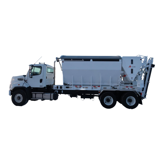
MX05001 • Safety Signs Decide on the exact position before you remove the backing paper. Always keep safety signs clean and legible. • Remove the smallest portion of the split Replace safety signs that are missing or have backing paper. become illegible. - Page 19 MX05001 3. Overall Description The major mixer system components are shown in the following figures. Table 1. Driver/Left Side System Components. Aggregate Bin Cement Bin Aggregate Control Gate Tarp Mixer Controls Enclosure Hydraulic pump Rev. 3 March 2022...
- Page 20 MX05001 Table 2. Right Side System Components. Mixing Auger Oil Reservoir Mixing Bowl Cement Bin Hydraulic Valve Enclosure Electrical Junction Box Oil Cooler Rev. 3 March 2022...
-
Page 21: Mixer Controls
MX05001 4. Controls, Instruments, and Operation Mixer Controls Table 3. Mixer Control Panel Table Mixer Control System (Computer) Emergency Stop Button • • Ranger ....Ranger Gunite Manual In ............. Stop • Mix Auger .......... Paddle Twist ..........Reset Master Switch ........On/Off Operating Keypad ...... -
Page 22: Mix Auger Paddle
MX05001 Mix Auger Paddle Table 4. Paddle Table Mix Auger Control ......Paddle • Up ..........Auger Up • Center ......No Movement • Down ........Auger Down Operator Control Rotate the Selection Knob until the desired the mixer computer manual.) Push the Selection speed is shown on the mixing computer (refer to Knob to accept the value. -
Page 23: Operating Keypad
MX05001 Operating Keypad The keypad operations are selected by pressing functions and status indicator lights are shown in the desired function button until the indicator the next section, Operating Keypad Status light on the button shows the colour Indications. corresponding to the associated mode. Button Figure 1. - Page 24 MX05001 Operating Keypad Status Indications Amber Green Solid Flashing Description Switch Indication ON (prints current job ticket) 1. Print Indicates a selectable vibrator, see computer manual for further details ON (holding this button will manually vibrate) Automatic (vibrator will engage at intervals set on the computer) 2.
- Page 25 MX05001 Automatic (indicates that this function is operating) Mixer fault (indicator only, refer to the computer manual for further details) 8. Cement Fee d Indicates a selectable vibrator, see computer manual for further details ON (holding this button will manually vibrate) Automatic (vibrator will engage at intervals set on the computer) 9.
-
Page 26: Valve Locations
MX05001 Valve Locations The following identifies valve locations for Numbers in the following figures correspond to hydraulic oil. the following valve locations. Valve Location 2. Full, Lean, Cement Bypass valve. Valve Location 1. Fibre feeder control valve, if equipped. Rev. 3 March 2022... - Page 27 MX05001 Valve Location 3. Gunite pump control valve, if equipped. Valve Location 4. Hydraulic oil control valve. Rev. 3 March 2022...
-
Page 29: Traditional Gunite Production Calibration Procedure
MX05001 5. Calibration The calibration of the mixer is the process that full by pressing button 8 – Cement Feed - on determines the control gate setting and the the Operating Keypad (refer to page 4-3.) meter count required to produce a certain mix 3. -
Page 30: Step 3: Sand Weight Per Count
MX05001 Step 3: Sand Weight per Count Equation 3. Sand Formula Determine the weight of sand that must be ������ ������������ ��������ℎ�� ���� �������� ������ �������� ������������ released per count. Using your mix design, ������������ ������ �������� ������������ ( �������� Step 2: ) establish the required weight of the sand to = ��������ℎ��... -
Page 31: Step 2: Counts Per Unit Volume Of Mix
MX05001 cement because its bulk density does not reflect entered. This is done in the mix entry screen real working conditions where cement has been after calibration (see Control System manual.) allowed to settle and compact. Ensure the Step 3: Gate Calibration cement is settled by driving the mixer or vibrating Determine the weight of sand that is released before samples are taken. -
Page 32: Fibre Feeder Calibration
MX05001 NOTE: After the control gate has been reset, the conveyor must be run until the adjusted material flow is past the discharge point. Disregard the material released during this operation and re- zero the meter. After calibrating using weight it is recommended that the yield of each mix be verified by batching concrete into a yield box (container of known volume) and comparing the results with that... -
Page 33: Principle Of Operation
MX05001 6. Field Operation Principle of Operation The ProAll Mobile Mixer is uniquely designed to An electronic counter allows the operator to allow for the supply of freshly mixed gunite, determine the accumulated amount of cement regardless of delivery times, the elimination of... -
Page 34: Cement Powder
MX05001 Cement Powder WARNING IMPORTANT: Care must be taken that no stone, water, or other foreign material enters the cement The exposed mixing auger is extremely bin. A serious malfunction of the cement feeding dangerous. The auger ball valve can system may result. -
Page 35: Drop-Away Bottom Mat
MX05001 Maintenance Frequency on page 7-9 for lubrication maintenance. The lower bearing supports the auger shaft and includes seals that help to keep materials from exiting the mix auger. Figure 6. Auger ball valve safety on/off (found by the conveyor drive motor). Drop-Away Bottom Mat The gunite auger offers a drop-away bottom mat to facilitate cleaning. -
Page 36: Auger Top Drive
MX05001 Auger Top Drive WARNING The mixing auger drive contains rotating components. Always keep the cover on the top drive while the mix auger is in use. IMPORTANT: The mix auger top drive must be greased regularly. Refer to Lubrication and Figure 9. -
Page 37: Fibre Feeder
MX05001 Fibre Feeder The ProAll fibre feeder is designed to supply a controlled flow of fibre strands to the gunite mix. NOTE: The fibre feeder discharge rate does not change proportionally with changes in the conveyor speed. Record the conveyor speed... -
Page 38: Setting Up To Pour
MX05001 Setting up to Pour manual for information on setting the mix values. Upon arrival at the pour site, confirm the 5. Set the aggregate bin discharge gate height specifications of the mix to be poured. Using the according to the desired mix design. SET AND following sequence, set up the mixer in LOCK THE CONTROL GATE. -
Page 39: Pouring
As with any machine, the operator of the ProAll mixer on subsequent loads. The operator should Mobile Mixer must understand and become... -
Page 40: Chain Oiler
MX05001 1. Using a scraper, remove any excess material 9. Master switch in the display box, or if from the discharge end of the conveyor belt. equipped with an engine, in the engine 2. Roll up the cement drop tube. enclosure - OFF Chain Oiler The chain oiler consists of the chain oil reservoir... -
Page 41: Tarp
MX05001 Tarp The tarp is used to cover the aggregate bin. Operate the tarp use the tarp control toggle switch located on the front, left-hand side of the machine. Figure 19. Tarp mechanism. Figure 18. Chain oiler brushes. Tarp Control The tarp control is a single toggle switch located Inspect the chain oil brushes periodically for on the left-hand side of the sand bin. -
Page 43: Maintenance
ProAll Mobile Mixer. Keeping your mixer Hydraulic System clean and free from cement build-up helps to Your ProAll Mobile Mixer has been filled with maintain a good image to your customers. The Petro Canada HYDREX™ XV to give you best all-... -
Page 44: Hydraulic Oil Filter
MX05001 Hydraulic Oil Filter The high-pressure hydraulic oil filter is included with the machine for the conveyor belt. Figure 24. High pressure filter indicator. Wear Plates The mix auger is equipped with replaceable wear plates, designed to protect the auger from Figure 22. -
Page 45: Service
Service position (resting on the conveyor belt.) If a service function requires that the pointer The ProAll Mobile Mixer has been designed and setting relative to the gate position be tested to allow for a minimum number of changed, return it to the original factory adjustments and service items. -
Page 46: Lubrication And Maintenance Points
MX05001 Lubrication and Maintenance Points The following inspection and maintenance aggressive aggregates, the nature of the mix schedule acts as a guideline only. It should be being produced and other factors will affect the noted that extreme weather conditions, frequency of service required. Rev. - Page 47 MX05001 Rev. 3 March 2022...
- Page 48 MX05001 Maintenance 1. Rear conveyor shaft grease and sensor gap check, left. Maintenance 4. Conveyor chain brush check. Maintenance 2. Front conveyor shaft, right and left. (1) bearing grease, (2) tension adjust Maintenance 5. Mix auger top bearing grease. Maintenance 3. Cement bin sump bearing grease. Maintenance 6.
- Page 49 MX05001 Maintenance 7. Lock arm grease. Maintenance 10. Rear conveyor shaft grease, right. Maintenance 11. Cement bin sump brush check. Maintenance 8. Lifting mechanism. (1) Lower lift link grease, (2) Boom cylinder Maintenance 9. Mix auger bottom grease Rev. 3 March 2022...
- Page 50 MX05001 Maintenance 14. Hydraulic reservoir check. (1) check oil level, (2) check return & suction filter. Maintenance 12. High pressure hydraulic oil filter Maintenance 13. Chain oil level check Rev. 3 March 2022...
-
Page 51: Lubrication And Maintenance Frequency
MX05001 Lubrication and Maintenance Frequency Table 7. Frequency Table Maint. Every Every Every Every Item Number Points Daily Load Rear conveyor shaft grease, right • Front conveyor shaft grease, right and left • Rear conveyor shaft sensor gap check • Cement bin sump bearing grease •... -
Page 52: Electrical Distribution Box
MX05001 Electrical Distribution Box The electrical timer, fuse and relay cabinet is display box master electrical switch (refer to located above the engine control panel on the page 6-6). The electrical functions – including left-hand side of the machine. NOTE: The lights and vibrators –... -
Page 53: Bolt Torque
MX05001 Bolt Torque The tables shown below give correct torque values for various bolts and capscrews. Tighten all bolts to the torque specified in chart unless otherwise noted. When assembling equipment, use bolt torque chart as a guide. Bolt Bolt Torque * Diameter SAE 2 SAE 5... - Page 55 To check for any alarms and their resolutions, please refer to the Ranger’s Operator’s Manual. If you have any further questions or need assistance, please contact the ProAll Customer Service at 8-335- PROALL (833-577-6255) Rev.
- Page 57 MX05001 9. 1st 50 Hour Service CHECK AND ADJUST AS REQUIRED 1. Check mixer tie down bolts are the proper torque, refer to Bolt Torque section on page 7-11. 2. Check all hydraulic connections for leaks and tighen, if necessary. Rev.
- Page 58 MX05001 10. Index aggregate bin, 6-1 definition, 2-4 aggregate flow, 6-7 lift cylinder, 7-3 aggregate gates, 6-1 adjustable clevis, 7-3 gate A, 6-1 cylinder pin, 7-3 auger cover, 6-2 lock arm, 7-7 bridging, 6-7 lower lift link, 6-4, 7-7 CAUTION lubrication solenoid valve, 6-8 definition, 2-4 maintenance schedule, 7-4...
- Page 59 unit volume, 5-1, 5-2, 5-3 WARNING upper lift link, 7-6 definition, 2-4 vibrate, 6-7 wear plates, 6-7, 7-2 vibrators, 7-10 weight of stone per count, 5-2 viscosity, 7-1 yield box, 5-2 viscosity range, 7-1 5810 - 47 Avenue, Olds, Alberta, Canada, T4H 1V1 E info@proallinc.com | P 403-335-9500 | F 403-335-9560 Rev.
Need help?
Do you have a question about the G Series and is the answer not in the manual?
Questions and answers