Table of Contents
Advertisement
Quick Links
• 取扱説明書(以下、本書といいます)の『製品使用上のご注意』の内容をよく理解し、本書をよく読んでか
ら操作してください。
Please understand well the contents of "Cautions on Product Use" of Instruction Manual (hereinafter
referred to as "this manual"), and operate it after often reading this manual.
• 本書はいつでも使用できるよう、大切に保管してください。
Please keep this manual carefully to be able to use it at any time.
レーザーマーカー用集塵機
Dust Collector
CBA-1500AT3-HC-DSA-V1
CBA-1500AT3-HC-DSA-V1-CE (220-230V)
チコーエアーテック株式会社
CHIKO AIRTEC CO., LTD.
for Laser Marker
取扱説明書
Instruction Manual
型式/MODELS
日
本
語
(200V)
Advertisement
Chapters
Table of Contents

Related Manuals for Chiko CBA-1500AT3-HC-DSA-V1


Summary of Contents for Chiko CBA-1500AT3-HC-DSA-V1
- Page 1 Please understand well the contents of "Cautions on Product Use" of Instruction Manual (hereinafter referred to as “this manual”), and operate it after often reading this manual. • 本書はいつでも使用できるよう、大切に保管してください。 Please keep this manual carefully to be able to use it at any time. チコーエアーテック株式会社 CHIKO AIRTEC CO., LTD.
- Page 2 揮できますよう正しいお取扱いをお願いします。 We greatly appreciate that you have purchased our dust collector for laser marker. CHIKO AIRTEC CO., LTD. is working to achieve clean air with compact equipment while utilizing “air technology” effectively. The dust collector for laser marker is an energy-saving-type clean box that realizes “air technology” in a compact body.
-
Page 3: Table Of Contents
1.5 その他のご注意 ................................... 4 1.6 危険シールの貼付位置................................5 第 2 章 各部の名称 ..............................6 2.1 付属品 ......................................6 2.2 装置本体 ......................................7 2.2.1 CBA-1500AT3-HC-DSA-V1 ............................7 2.3 AT3 パネル ...................................... 8 2.4 ディスプレイ表示 ..................................9 2.4.1 モードについて ..................................9 2.4.2 停止中の表示 ..................................9 2.4.3 運転中の表示... - Page 4 6.1.2 ピンアサイン ..................................29 6.1.3 リモート操作 ..................................30 6.2 通信機能 ....................................... 30 6.2.1 RS485 通信 ..................................30 6.2.2 イーサネット ..................................30 第 7 章 付録 ................................31 7.1 仕様 ......................................... 31 7.2 消耗品リスト ....................................31 7.3 電気回路図 ....................................32 7.3.1 CBA-1500AT3-HC-DSA-V1 ............................32...
-
Page 5: 第1章 製品使用上のご注意
第 1 章 製品使用上のご注意 第1章 製品使用上のご注意 日 本 語 1.1 安全に関する表記 この取扱説明書には、使用時の注意事項が下記の記号とともに記載されています。 必ずお読みください。 記 号 意 味 正しく使用しない場合、取扱者が死亡または重傷を負う危険性がある注意事項が記載され 警 告 ています。 正しく使用しない場合、取扱者が傷害を負う危険性や本装置を損傷する恐れがある注意 注 意 事項が記載されています。 行ってはいけない「禁止」の内容です。 必ず実行する「強制」の内容です。 1.2 運搬・保管・輸送時のご注意 • 運搬は台車等を使用し、二人以上で行って下さい。 警 告 落下などにより、けがをする恐れがあります。 • 輸送・保管は安全な場所で、温度-10℃~60℃ 湿度 80%以下の範囲としてくださ 注 意 い。... -
Page 6: 運転時のご注意
第 1 章 製品使用上のご注意 1.4 運転時のご注意 • 次の物質は吸引しないでください。 引火性物質 ..... ガソリン・シンナー・ベンジン・灯油・塗料など。 爆発性粉塵 ..... アルミニウム・マグネシウム・チタン・亜鉛・エポキシなど 火花を含んだ粉塵 ..高速切断機・グラインダー・溶接機などから発生する火 花を含んだ粉塵。 火種 ........たばこ・油・薬品などの液体 その他 ....... 水・油・薬品などの液体 • 引火性・爆発性・腐食物質の霧・煙・ガスが滞留している場所や、これらの付近 警 告 で使用しないでください。 • 接続は、確実に行い、ケーブルを無理に曲げたり、引っ張ったりしないでくださ い。 火災・感電の原因になります。 • 本機の仕様と異なる電源で使用しないでください。 • 粉塵爆発のおそれのない乾いた粉塵の吸引に使用してください。 • アース線は必ず接続して使用してください。 • 運転中は移動させないでください。 •... -
Page 7: 危険シールの貼付位置
第 1 章 製品使用上のご注意 1.6 危険シールの貼付位置 日 本 語 高温警告シール 高電圧警告シール 分解禁止シール ネームプレート 高電圧警告シール 高温警告シール 分解禁止シール ネームプレート CMN023-005 原文の翻訳 (Translation of the original instructions) -
Page 8: 第2章 各部の名称
第 2 章 各部の名称 第2章 各部の名称 2.1 付属品 ① ② ③ 200V 仕様 220-230V 仕様(-CE 仕様) ④ ⑤ ⑥ 番号 名称 働き 数量 ① 1 次フィルタ 粉塵やヒュームを収集・吸着します。 ② 2 次フィルタ 電気部品を粉塵から守ります。 ③ 活性炭カセット 臭いを吸着します。 ④ 排気 HEPA フィルタ 排気をクリーンにします。 電源コンセントに接続します。 200V 仕様... -
Page 9: 装置本体
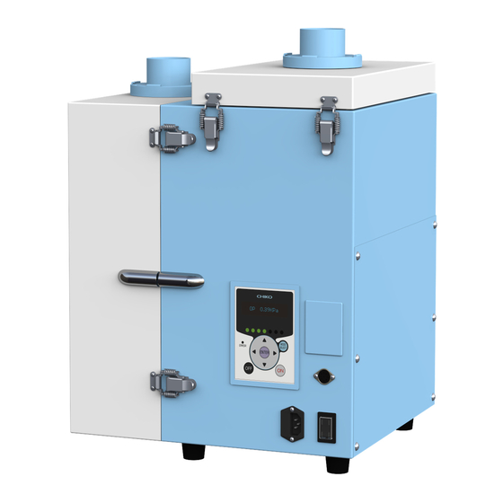
第 2 章 各部の名称 2.2 装置本体 日 本 語 2.2.1 CBA-1500AT3-HC-DSA-V1 ⑪ ⑫ ⑬ ① ⑩ ② ⑨ ⑧ ⑦ ④ ⑤ ⑥ ③ 番号 名称 働き ① 吸込み口 吸気ダクトを接続します。 ② 吸気側フィルタケース 1 次フィルタを収納しています。 ③ 1 次フィルタ 粉塵やヒュームを収集・吸着します。 ④ シェイキングモータ室... -
Page 10: At3 パネル
第 2 章 各部の名称 2.3 AT3 パネル ① ② ③ ④ ⑨ ⑤ ⑤ ⑧ ③ ⑥ ⑦ 番号 名称 働き 有機 EL(OLED) 運転状態や各種設定内容を表示します。 ① ディスプレイ エラー・警告発生時は、エラー・警告 No.を表示します。 ② 能力レベルランプ 能力レベルを緑色のランプで表示します。(レベル 1~7) 停止中、運転中は、ディスプレイの表示内容を切り替えます。 「2.4 ディスプレイ表示」(9 ページ) ③ ↑/↓ボタン モードセレクトモード時は、設定項目の切り替えと設定する数値データを変更 します。 「第... -
Page 11: ディスプレイ表示
第 2 章 各部の名称 2.4 ディスプレイ表示 日 本 語 2.4.1 モードについて 通常モード モードセレクトモード 主電源スイッチ 停止中 ページ モードセレクトボタン 初期圧登録クリア ページ OFF ボタン ON ボタン OFF ボタン 3 秒押し 初期圧登録 運転中 ページ ENTER ボタン 3 秒押し 2.4.2 停止中の表示 ↑/↓ボタンで表示を切り替えることができます。 Ver*.** ID.** プログラムバージョン、RS485 通信用局番 Battery ***% 電池残量... -
Page 12: 運転中の表示
第 2 章 各部の名称 2.4.3 運転中の表示 ↑/↓ボタンで表示を切り替えることができます。 **.**kPa 外部圧 **.**kPa 吸込圧 **.**kPa 差圧 **.**kPa 排気圧 Blower ***.*℃ ブロア周辺温度 Moter ******rpm モータ回転数 積算稼動時間(リセット可) Runtime ******h リセット後からの稼動時間を表示します。 ページ 積算稼動時間リセットモード( ) 実動時間(リセット不可) Total ******h トータルの稼動時間を表示します。... -
Page 13: 第3章 運転
第 3 章 運転 第3章 運転 日 本 語 3.1 運転前の準備 3.1.1 設置 ■ 設置場所 使用上安全および本機の性能を十分に発揮させるため、下記の条件を満たす場所に設置してください。 項 目 内 容 周 囲 温 度 0℃~+40℃の範囲 周 囲 湿 度 80%RH 以下の範囲(結露のないこと) 雰 囲 気 屋内(直射日光が当たらないこと)、腐食性ガス・引火性ガス・オイルミスト・粉塵のないこと ■ ご使用になる前に必ず剥がしてください 「REMOVE」 ステッカー 出荷時には、輸送中に 1 次フィルタのゼオライトが飛び散らないよう に、フィルタにステッカーを貼っています。ご使用になる前に、本体から... - Page 14 第 3 章 運転 ■ ボタン電池絶縁シートの取り外し ボタン電池の絶縁シートを取り外す際には通電状態で行ってください。 ボタン電池の絶縁シートを取り外してください。 電池カバー 吸気側フィルタケースのパッチン錠(2 ヶ所)を 吸気側フィルタケース 外します。 吸気側フィルタケースを開きます。 パッチン錠 電池カバー部から絶縁シートを矢印の方向(左 または下)に引き抜きます。 電池カバー 絶縁シート 注 意 • 本体を通電せず絶縁シートを引き抜くと、著しく電池が消耗することがあります。 • ボタン電池は主電源スイッチが OFF のときに消費されます。 メ モ 主電源 ON 時(1μA 以下)、主電源 OFF 時(40~50μA) • 電池寿命(参考値:約 2 年)は、使用状況によって変わります。目安としてください。...
-
Page 15: 配線・配管
第 3 章 運転 3.1.2 配線・配管 日 本 ■ 配線 語 • 接続は確実に行い、ケーブルを無理に曲げたり、引っ張ったりしないでください。 火災・感電の原因になります。 警 告 • 本機の仕様と異なる電源で使用しないでください。 • アース線は必ず接続して使用してください。 • 電圧低下の原因になりますので、タコ足配線にしないでください。 注 意 電圧が降下すると正常に動作しなくなり、故障の原因になります。 本機の電源は、単相電源です。 供給電圧の許容範囲は、±10%です。 電源コードの本体差し込みプラグを本機の電源コネクタに接続します。 電源コードの電源側を電源に接続します。 ■ 配管 吸気配管(別途ご準備)をフランジに接続します。 • 適切な配管で運転してください。 重 要 配管はできるだけ短くし、配管口径は狭くしすぎないでください。 3.2 運転 主電源スイッチを ON にします。 ディスプレイにプログラムバージョンと... -
Page 16: 初期圧登録
第 3 章 運転 3.3 初期圧登録 初期登録した差圧からフィルタ目詰まりによる風量低下を判定し、風量不足(WARN4)としてお知らせします。 次の手順で、初期圧力を登録してください。 本機を配線、配管します。 任意の能力で運転を開始します。 ENTER ボタンを 3 秒間長押しします。 ディスプレイに“Initial DP Get Y”と表示され、初期圧力の更新登録を実施するか確認されます。 更新登録を実施する場合は ENTER ボタンを押します。 初期圧力の取得動作を開始します。 実施しない場合は、MODE SELECT ボタンを押すと通常動作に戻ります。 能力レベル 1 から 7 まで順番に運転し、各能力レベルの差圧を自動取得します。 初期圧力の取得動作中は、ディスプレイに“Initial DP Check”と「能力レベルと差圧」が交互に表示されま す。 登録が完了すると、ディスプレイに“Initial DP Entry”と表示されて通常動作に戻ります。 • フィルタが必ず新品の状態で行ってください。 • 初期圧力登録後、配管を変えた場合やフィルタを全て交換された場合(排気フィルタ除 重... -
Page 17: 第4章 各種設定(モードセレクトモード
第 4 章 各種設定(モードセレクトモード) 第4章 各種設定(モードセレクトモード) 日 本 語 4.1 モードセレクトモードでの画面遷移 停止中に MODE SELECT ボタンを押すとモードセレクトモードに移行します。 ↑/↓ボタンで設定項目を切り替えます。 シェイキング設定モード [Shaking Set] ( ページ) 通信フォーマット設定モード [Com Setting] ( ページ) 風量不足お知らせタイミング設定モード [Volume Down ST] ( ページ) その他の設定モード [Other Setting] ( ページ) エラー履歴モード [Error Data] (... -
Page 18: シェイキング時間設定モード
第 4 章 各種設定(モードセレクトモード) 4.2.2 シェイキング時間設定モード シェイキング稼動時間を任意で変更できます。 (設定可能範囲: 20~180 秒 初期設定値: 20 秒) モードセレクトモードに移行します。 ↑/↓ボタンを押してシェイキング設定モード(“Shaking Set”)に移行します。 ENTER ボタンを押します。 ↑/↓ボタンを押してシェイキング時間設定モード(“Shake Time ***sec”)に移行します。 ENTER ボタンを押します。 ←/→ボタンで桁を、↑/↓ボタンで数値を変更します。 ENTER ボタンを押して数値を決定します。 終了する場合は、MODE SELECT ボタンを押して、通常モードに戻ります。 4.2.3 オートシェイキングのインターバル時間設定モード オートシェイキングが稼動するまでの積算時間を任意で変更できます。 (設定可能範囲: 0~60 分 初期設定値: 60 分) モードセレクトモードに移行します。 ↑/↓ボタンを押してシェイキング設定モード(“Shaking Set”)に移行します。 ENTER ボタンを押します。... -
Page 19: 通信フォーマット設定モード(通信機能装備時
第 4 章 各種設定(モードセレクトモード) 4.3 通信フォーマット設定モード(通信機能装備時) 日 本 語 シリアル通信フォーマットの以下の項目を設定します。 設定した内容は主電源スイッチでの再起動後に有効になります。 項 目 設定内容 標準出荷設定値 通信局番 1~25 9600bps、19200bps、 ボーレート 38400bps、57600bps、 9600bps 115200bps ビット長 8bit パリティなし ビット長 8bit パリティ奇数 ビット長とパリティ ビット長 8bit パリティなし ビット長 8bit パリティ偶数 ビット長 9bit パリティなし ストップビット 1 ビット ストップビット... -
Page 20: その他の設定モード
第 4 章 各種設定(モードセレクトモード) 4.5 その他の設定モード 以下の項目を設定します。 • 日付と時刻の設定 「4.5.1 時刻合わせモード」(18 ページ) • 積算稼動時間のリセット 「4.5.2 積算稼動時間リセットモード」(18 ページ) • 設定データのリセット 「4.5.3 設定値リセットモード」(19 ページ) 4.5.1 時刻合わせモード 日付と時刻を設定します。 モードセレクトモードに移行します。 ↑/↓ボタンを押してその他の設定モード(“Other Setting”)に移行します。 ENTER ボタンを押します。 “Time Adjust”が表示されます。 ENTER ボタンを押します。 日付の設定画面になります。 ↑/↓ボタンを押して数値を変更します。 ENTER ボタンを押して数値を決定します。 年、月、日の順に設定します。 日付が設定されると、時刻の設定画面になります。 ↑/↓ボタンを押して数値を変更します。... -
Page 21: 設定値リセットモード
第 4 章 各種設定(モードセレクトモード) 4.5.3 設定値リセットモード 日 通信フォーマットと風量不足お知らせタイミングを標準出荷設定値に戻し、積算稼動時間をリセットします。 本 語 モードセレクトモードに移行します。 ↑/↓ボタンを押してその他の設定モード(“Other Setting”)に移行します。 ENTER ボタンを押します。 “Time Adjust”が表示されます。 ↑/↓ボタンを押して、表示を“[Setting Reset]”にします。 ENTER ボタンを押します。 “1:YES”と表示され、設定値をリセットするか確認されます。 リセットする場合は ENTER ボタンを押してください。 再確認のため、“1:START”と表示されます。 ENTER ボタンを押すと設定値がリセットされ、通常モードに移行します。 4.6 エラー履歴モード 4 件分のエラー履歴を確認することができます。 エラー履歴は主電源スイッチを OFF するとクリアされます。 モードセレクトモードに移行します。 ↑/↓ボタンを押してエラー履歴モードに移行します。 ENTER ボタンを押します。 直近で発生したエラーNo と発生したときの積算稼動時間が表示されます。 ↓ボタンを押すと、新しい順に... -
Page 22: 第5章 保守・点検
第 5 章 保守・点検 第5章 保守・点検 • 保守・点検時は必ず電源を切り、コンセントからプラグを抜いて、電路遮断を行っ 注 意 てください。 5.1 フィルタの交換 目詰まりした場合、「WARN2」の警告が表示されますので、1 次フィルタを交換してください。 5.1.1 1 次フィルタの交換 • 1 次フィルタの交換は、吸気側フィルタケースを開くことができる十分なスペースがある場 重 要 所で行ってください。 吸気側フィルタケースのパッチン錠(2 ヶ 1 次フィルタ 吸気側フィルタケース 所)を外します。 吸気側フィルタケースを開け、1 次フィルタ を取り外します。 パッチン錠 新しい 1 次フィルタを取り付けます。 吸気側フィルタケースを閉じ、パッチン錠(2 ヶ所)で固定します。... -
Page 23: 次フィルタの交換
第 5 章 保守・点検 5.1.2 2 次フィルタの交換 日 本 • 2 次フィルタの交換は、吸気側フィルタケースを開くことができる十分なスペースがある場 語 重 要 所で行ってください。 吸気側フィルタケースのパッチン錠(2 ヶ シェイキングガード シェイキングアーム 所)を外します。 吸気側フィルタケースを開けます。 シェイキングアームが中心で停止している 場合は、端に動かしてからガード等を取り パッチン錠 外してください。 シェイキングガードの両端にある 2 ヶ所の ネジを外し、ガードを取り外します。 フィルタ押さえ板の両端にある 2 ヶ所のネ ジ を外し、押さえ板を取り外します。 フィルタ押さえ板 2 次フィルタを取り外します。 2 次フィルタ 吸気側フィルタケース... -
Page 24: ヒューズの交換
第 5 章 保守・点検 ACC プレートを持ち上げて、活性炭カセット ACC プレート を取り外します。 活性炭カセット 新しい活性炭カセットを取り付けます。 新しい排気フィルタを取り付けます。 排気フィルタ室を元通りに取り付けます。 ※活性炭カセットは、排気の臭い気になる場合 に交換してください。 5.2 ヒューズの交換 内部機器のトラブルによる過電流でヒューズが切れた時は、ヒューズ(1 個)を交換してください。 ヒューズは、電源スイッチの左側の黒いボックス内にあります。 ヒューズの交換の際には、弊社規定のヒューズをお使いください。 規定ヒューズ:Littell fuse 製 218 シリーズ 250V 15A ヒューズボックスのカバーを開きます。 カバー ヒューズ カバーは取り外すことはできません。 マイナスドライバなどの先の細いものでヒ ューズボックスを取り出します。 ヒューズボックス内のヒューズを交換しま す。... -
Page 25: ボタン電池の交換
第 5 章 保守・点検 5.3 ボタン電池の交換 日 本 語 • 本機で使用しているボタン電池のケースは、CR2477 サイズ用です。 注 意 CR2477 以外のボタン電池は使用しないでください。 • 本体を通電せずに電池を交換すると著しく電池が消耗することがあります。 本体を通電して下さい 吸気側フィルタケースを開きます。 電池カバー 電池カバーのネジ(2 個)を外し、電池カバ ーを取り外します。 ネジ 爪を右に押し、ボタン電池を取り外します。 ボタン電池 爪 新しいボタン電池に交換します。 電池カバーを元通りに取付けます。 本体の電源を遮断して下さい。 5.4 日常点検 点検項目 頻 度 点検内容 フィルタケース 運転前 完全に閉じているか 吸込口... -
Page 26: エラー・警告
第 5 章 保守・点検 5.6 エラー・警告 本機には、エラー・警告が発生すると異常ランプを点灯(点滅)させ、ディスプレイに表示データとエラーNo.を交 互に表示する自己診断機能があります。 「5.6.2 」(25 ページ) 表示されるエラー・警告の内容については エラー・警告一覧 を参照してください。 「5.7 」(26 ページ) 自己診断されない故障等については、 故障と思ったら を参照してください。 5.6.1 エラー・警告の処置方法 本機の自己診断機能によりエラー・警告が発生した場合は、以下の操作を行いエラー・警告を解除してください。 説明用の画面は例として記載しています。 エラー・警告が発生すると、異常ランプが点灯 ????? (表示データ) (点滅)しディスプレイに表示データとエラーNo. が交互に表示されます。 交互に表示 複数のエラー・警告が発生しているときは、優 (エラーNo.) ERR04 先順位の高いものが表示されます。 MODE SELECT ボタンを押し、エラー履歴モー 2:ERR04 ドに移行します。 複数のエラー・警告が発生しているときは、エ 優先順位の高いエラーNo. -
Page 27: エラー・警告一覧
第 5 章 保守・点検 5.6.2 エラー・警告一覧 日 本 優先 エラー・警告 異常 本機の エラーNo. 内容 方法 語 順位 名 ランプ 動作 「5.7 故障と思ったら」の②の モータの回転数が下が 運転 対策方法に従って処置を行 ERR03 回転数異常 っている(また停止して 点滅 継続 ってください。 いる) 26 ページ ( ) 「5.7 故障と思ったら」の②の 高 ブロア周辺温度が異常 対策方法に従って処置を行... -
Page 28: 故障と思ったら
第 5 章 保守・点検 5.7 故障と思ったら 番号 故障現象 原 因 対策方法 電源が ON になってい 電源を ON にする。 ない 有機 EL ディスプレイが ① 表示しない ヒューズを交換する。 ヒューズが切れている 「5.2 ヒューズの交換」(22 ページ) モータ故障を起こして 修理を依頼してください。 いる モータ交換になります。 [1] 排気口/吸引口が塞がれていないか確認 する。 [2] 定格電圧を確認する。 [3] タコ足配線になっていないか確認する。 [4] フィルタの目詰まりや吸込み温度によりモ ータが過熱していないか確認する。... -
Page 29: 第6章 便利な使い方(オプション
第 6 章 便利な使い方(オプション) 第6章 便利な使い方(オプション) 日 本 語 6.1 リモートケーブル 6.1.1 標準接続図 CMN023-005 原文の翻訳 (Translation of the original instructions) - Page 30 第 6 章 便利な使い方(オプション) ■ 接続例 ● ①、④ピン(入力) 電圧を印加しないでください。 参考回路 ● ②ピン(アナログ出力) 出力電圧:1~5V±0.2V 計測器等 参考回路 ● ③、⑤、⑥ピン(オープンコレクタ出力) 定格を超えないよ うに保護回路を追 加してください。 ⑤ピンが LOW の時、負荷に電 ③または⑤ 流が流れます。 または⑥ピン 参考回路 推奨 DC 電圧・電流:最大定格の 1/2 以下 ● ⑦ピン(入力) 参考回路...
-
Page 31: ピンアサイン
第 6 章 便利な使い方(オプション) 6.1.2 ピンアサイン 日 本 ピン 線色 信号名称 内 容 語 番号 黒 ① 運転入力信号* ④と⑧を短絡後、①を短絡して運転を開始します。 ④と⑧を短絡してリモート操作に移行させます。 赤/白 ④ 遠隔操作切替信号* 短絡すると AT3 パネルの通常操作はできなくなりま 遠隔信号 す。 (入力) ⑦と⑧の間で、0~5V の電圧を印加することで能力 黄 ⑦ 能力レベル変更* レベルを変更することができます。 黄/白 ⑧ ― 現在の運転圧力を出力します。 黒/白 ②... -
Page 32: リモート操作
第 6 章 便利な使い方(オプション) 6.1.3 リモート操作 • リモート操作で運転 ON/OFF する場合は、④ピンと⑧ピンを短絡させておきます。 ①ピンを短絡→運転 ON ①ピンを短絡しない→運転 OFF 「6.1.2 ピンアサイン」(29 ページ)を参照してください。 • 本機側の操作で運転 ON/OFF して信号を取り出す場合は、④ピンと⑧ピンを短絡させないでください。 「6.1.2 ピンアサイン」の説明に従い、必要な出力信号を取り出してください。 • リモート操作移行中に本機側で、初期圧登録・運転 ON/OFF の操作・能力レベルを変更することはできませ ん。 • 能力レベルを変更する時にレベルが記憶されるため、万が一主電源を切っても前回の能力レベルを記憶し ています。リモート操作で ON/OFF する場合は、④ピンと⑧ピンを短絡させておきます。 6.2 通信機能 オプションの通信ボードセット(型式:RS-485 又は RS-EN)を使用する事で、運転 ON/OFF や、フィルタ目詰ま り等の情報を取り出す事が可能です。... -
Page 33: 第7章 付録
第 7 章 付録 第7章 付録 日 本 語 7.1 仕様 モータ 最大 最大 型式 電圧 電流値 周波数 騒音値* 質量 定格出力 吸込風量 吸込静圧 CBA-1500AT3-HC-DSA 200V 1140W 11.6A 50/60Hz 4.1m /min 15.0kPa 55-58dB 41.8kg 単相 CBA-1500AT3-HC-DSA 220-230V 1140W 11.6A 50/60Hz 4.1m /min 15.0kPa 55-58dB... -
Page 34: 電気回路図
第 7 章 付録 7.3 電気回路図 7.3.1 CBA-1500AT3-HC-DSA-V1... - Page 35 ■保証と責任の範囲 ●保証期間 正常な使用状態で、故障または損傷が生じた場合には、出荷後 12 ヶ月間は無料で修理いたします。 ただし、7.2 消耗品リストに記載の消耗品は除きます。 「7.2 消耗品リスト」(31 ページ) 下記のような場合は保証期間内でも有償とさせていただきます。 • 本書に記載されている注意事項を順守しなかった場合に発生した故障または損傷の場合 • 本書に記載されている使用環境以外での使用による故障または損傷の場合 • 弊社および弊社指定の販売店以外で修理・改造・分解等をした場合 • 使用中に生じたキズ、汚れなどの外観上の変化の場合 • 消耗品・付属品の交換および弊社指定以外の部品を使用した場合 • お買い上げ後の落下、および運送上の事故による故障または損傷の場合 • 火災、塩害、ガス害、地震、風水害、落雷、電圧異常およびその他の天変地異を原因とする故障または損 傷の場合 ●修理について 出張修理をご希望の場合、出張料金は、保証期間内外を問わず有料となります。 修理の都合により、修理時に改良部品を使用する場合がございます。 本機の故障による損害、データの抹消による損害、その他本機の使用により生じた損害について、弊社は一 切その責任を負いかねますので、ご了承ください。 ■お買い上げメモ 型 式 製造番号 購入年月日 運転開始日 年 月 お客様お名前 住所...
- Page 37 Safety Label Locations ........................39 Chapter 2 Components Identification ................40 Accessories ........................... 40 Device Body ..........................41 2.2.1 CBA-1500AT3-HC-DSA-V1 ....................41 AT3 Panel ............................42 Display Indications ........................43 2.4.1 About Modes .......................... 43 2.4.2 Indications during Stoppage ....................43 2.4.3 Indications during Operation ....................
- Page 38 6.1.2 Pin Assignments ........................62 6.1.3 Remote Operation ......................... 63 Communication Function ....................... 63 6.2.1 RS485 Communication ......................63 6.2.2 Ethernet ..........................63 Chapter 7 Appendix ......................64 Specifications ..........................64 Consumables List .......................... 64 Electrical Diagram ......................... 65 7.3.1 CBA-1500AT3-HC-DSA-V1 ....................65...
-
Page 39: Chapter 1 Product Usage Precautions
Chapter 1Product Usage Precautions Chapter 1 Product Usage Precautions Safety Notations This instruction manual describes usage precautions with the below listed symbols. Be sure to read the instructions. Symbol Meaning Indicates a hazardous situation which, if not avoided, could result in personal death or WARNING serious injury. -
Page 40: Precautions For Operation
Chapter 1Product Usage Precautions Precautions for Operation • Do not suck the following substances: Flammable substances ... Gasoline, thinner, benzine, kerosene, paints, etc. Explosive dusts ... Aluminum, magnesium, titanium, zinc, epoxy, etc. Sparky dust ....Dust containing sparks from high-speed cutting machine, grinder, welding machine, etc. -
Page 41: Safety Label Locations
Chapter 1Product Usage Precautions Safety Label Locations High temperature warning label High voltage warning label “ ” label Name plate “Do not Name plate High voltage High warning label temperature disassemble” warning label label CMN023-005 原本 (original instructions) -
Page 42: Chapter 2 Components Identification
Chapter 2Components Identification Chapter 2 Components Identification Accessories ① ② ③ 200V version 220-230V version (-CE version) ④ ⑤ ⑥ Name Function Qty. Primary filter Collects/adsorbs dust and fumes. ① Secondary filter Protects electrical parts from dust. ② Activated carbon Adsorbs odors. -
Page 43: Device Body
Chapter 2Components Identification Device Body 2.2.1 CBA-1500AT3-HC-DSA-V1 ⑪ ⑫ ⑬ ① ⑩ ② ⑨ ⑧ ⑦ ④ ⑤ ③ ⑥ Name Function Suction port Connects a suction duct. ① Filter case on the intake Houses the primary filter ② side Collects/adsorbs dust and fumes. -
Page 44: At3 Panel
Chapter 2Components Identification AT3 Panel ① ② ③ ⑨ ④ ⑤ ⑤ ③ ⑧ ⑦ ⑥ Name Function Organic EL Displays the operating status and various settings. ① (OLED) display Displays an error or warning number in case of an error or warning. Suction power Green lamps indicate a suction power level (1 to 7). -
Page 45: Display Indications
Chapter 2Components Identification Display Indications 2.4.1 About Modes Normal mode MODE SELECT Mode Main power During stoppage Page 49 switch ON MODE SELECT button Clearing registered OFF button Initial Pressures ON button OFF button Held down for 3 sec Page 48 Registering Initial During operation ENTER button... -
Page 46: Indications During Operation
Chapter 2Components Identification 2.4.3 Indications during Operation The Up/Down arrow buttons cycle through indications. External pressure **.**kPa Suction pressure **.**kPa Differential pressure **.**kPa Exhaust pressure **.**kPa Temperature around blower Blower ***.*℃ Motor rotational frequency Moter ******rpm Accumulated run time (resettable) Indicates run time accumulated since the last Runtime ******h... -
Page 47: Chapter 3 Operation
Chapter 3Operation Chapter 3 Operation Start-up Preparation 3.1.1 Installation ■ Installation location To ensure operating safety and deliver the full performance of the device, install the device in a location that meets the following conditions: Item Description Ambient temperature 0℃ to +40℃ Ambient humidity 80 RH% or lower (without dew condensation) Ambient conditions... - Page 48 Chapter 3Operation ■ Removing the button battery insulating sheet While removing the insulation sheet from the button battery, turn on the electricity. Remove the insulation sheet from the Battery cover button battery. Release the two snap locks for suction-side Suction-side filter filter case.
-
Page 49: Wiring And Piping
Chapter 3Operation 3.1.2 Wiring and Piping ■ Wiring • Perform wiring firmly, without bending or pulling cables with excessive force. Fire or electric shock may result. WARNING • Ensure that the power supply conforms to the specifications of the device. •... -
Page 50: Registering Initial Pressures
Chapter 3Operation Registering Initial Pressures Air volume reduction due to filter clogging is judged based on a registered initial differential pressure and indicated as low air volume (WARN4). Register initial pressures through these steps: Perform the wiring and piping of the device. Start the device at a desired suction power level. -
Page 51: Chapter 4 Configuring Settings【Mode Select Mode
Chapter 4Configuring Settings【MODE SELECT mode】 Chapter 4 Configuring Settings【MODE SELECT mode】 Screen Transitions in MODE SELECT Mode To move to the MODE SELECT mode, press the MODE SELECT button during stoppage. The Up/Down arrow buttons cycle through parameters. Shaking Setting mode [Shaking Set] (... -
Page 52: Time Setting Mode For Shaking
Chapter 4Configuring Settings【MODE SELECT mode】 4.2.2 Time Setting Mode for Shaking The shaking time can be adjusted as desired. (Settable range: 20 to 180 seconds. Initial setting value: 20 seconds) Move to the MODE SELECT mode. Press the Up/Down arrow buttons to move to the shaking setting mode (“Shaking Set”). Press the ENTER button. -
Page 53: Air Volume-Down Alert Timing Setting Mode
Chapter 4Configuring Settings【MODE SELECT mode】 Air Volume-Down Alert Timing Setting Mode This mode allows for changing the timing for displaying an air volume-down warning (WARN4) as desired. Move to the MODE SELECT mode. Press the Up/Down arrow buttons to move to the air volume-down alert timing setting mode (“Volume Down ST”). -
Page 54: Accumulated Run Time Reset Mode
Chapter 4Configuring Settings【MODE SELECT mode】 Press the Up/Down arrow buttons to change the value. Press the ENTER button to determine the value. Set the value in this order: hours, minutes, and seconds. To exit this mode, press the MODE SELECT button to return to normal mode. 4.5.2 Accumulated Run Time Reset Mode This mode resets the accumulated run time (“Runtime”). -
Page 55: Chapter 5 Maintenance And Checkup
Chapter 5Maintenance and Checkup Chapter 5 Maintenance and Checkup Before starting maintenance and checkup, be sure to break the electrical circuit by turning off the power supply and disconnecting the plug from the CAUTION power outlet. Replacing Filters If there is clogging, the warning "WARN 2" is displayed. Replace the primary filter. 5.1.1 Replacing the Primary Filter •... -
Page 56: Replacing The Secondary Filter
Chapter 5Maintenance and Checkup 5.1.2 Replacing the Secondary Filter • Replace the secondary filter in an area where there is sufficient space for opening IMPORTANT the air inlet filter. Release the two snap locks on the filter shaking guard Shaking arm case on the intake side. -
Page 57: Replacing Fuse
Replace a fuse if any of them is blown by an overcurrent due to trouble with internal equipment. The fuse is contained in the black box on the left of the power switch. The replacing fuse should be designated by CHIKO AIRTEC. Designated fuse:218 Series from Littell fuse 250 V, 15A Open the cover of the fuse box. -
Page 58: Daily Checkup
Chapter 5Maintenance and Checkup Push the claw rightward and remove the Button Battery Claw button battery. Replace with a new button battery. Install the battery cover back in place. Cut off the electricity of the device. Daily Checkup Check item Frequency Check that: Filter case... -
Page 59: Errors/Warnings
Chapter 5Maintenance and Checkup Errors/Warnings If an error/warning occurs, the self-diagnosis function built-in the device lights (flashes) the ERROR lamp and shows display data and error number alternately on the display. For a description of errors/warnings displayed, see ”5.6.2 Error/Warning Table(Page 58 ”. -
Page 60: Error/Warning Table
Pressure error low pressure for more Stop “5.7 Troubleshooting” than preset period. Page 59). F-RAM write Remains ERR07 Cannot write to F-RAM. Flashing Contact CHIKO AIRTEC. error operational Communication BCC judgment Remains ERR08 Flashing Contact CHIKO AIRTEC. error mismatch operational... -
Page 61: Troubleshooting
Replace filters. Clogged filter “5.1 Replacing Filters” (Page 53) Foreign matter Call for repair. Odd noise or vibration entered in blower. ⑤ from motor Broken motor bearing Call for repair. Note: For other phenomena, contact CHIKO AIRTEC. CMN023-005 原本 (original instructions) -
Page 62: Chapter 6 Useful Utilization (Optional)
Chapter 6Useful Utilization (Optional) Chapter 6 Useful Utilization (Optional) Remote Cable Standard connection diagram 6.1.1 Relay Relay Relay... - Page 63 Chapter 6Useful Utilization (Optional) ■ Connection examples ● Pins ① and ④ (input) Device side Customer side Do not apply voltage. Pin ① or ④ Pin ⑧ Reference circuit ● Pin ② (analog output) Device side Customer side Output voltage: 1 to 5 V 0.2 V Measuring instrument, etc.
-
Page 64: Pin Assignments
Chapter 6Useful Utilization (Optional) 6.1.2 Pin Assignments Wire color Pin # Signal name Description Operation input With ④ and ⑧ short-circuited, ① is short- Black ① signal circuited to start operation. ④ and ⑧ are short-circuited to start remote Remote control operation. -
Page 65: Remote Operation
Chapter 6Useful Utilization (Optional) 6.1.3 Remote Operation • For operation on/off switching via remote operation, short-circuit pins ④ and ⑧. Pin ① is short-circuited operation ON Pin ① is not short-circuited operation OFF “6.1.2 Pin Assignments” (page 62). •... -
Page 66: Chapter 7 Appendix
Chapter 7Appendix Chapter 7 Appendix Specifications Max. Max. Motor rated Current suction Noise Model Voltage Frequency suction Mass output value static value* volume pressure CBA-1500AT3-HC-DSA 200V 1140W 11.6A 50/60Hz 4.1m /min 15.0kPa 55-58dB 41.8kg Single phase CBA-1500AT3-HC-DSA 220V to 230V 1140W 11.6A 50/60Hz... -
Page 67: Electrical Diagram
Chapter 7Appendix Electrical Diagram 7.3.1 CBA-1500AT3-HC-DSA-V1 CMN023-005 原本 (original instructions) - Page 68 Travel expenses for on-site service will be chargeable whether within or outside the warranty period. For repair reasons, improved parts may be used for repair. CHIKO AIRTEC will not be liable for any damage resulting from use of this device, such as damage caused by failure of the device or by erasion of data.
- Page 69 MEMO...
- Page 70 チコーエアーテック株式会社 CHIKO AIRTEC CO.,LTD. 〒562-0012 大阪府箕面市白島 2-27-24 2-27-24,Hakushima, Minoh, Osaka 562-0012, Japan TEL (81) 072-720-5151 FAX (81) 072-720-5133 URL http://chiko-airtec.jp/...
Need help?
Do you have a question about the CBA-1500AT3-HC-DSA-V1 and is the answer not in the manual?
Questions and answers