Table of Contents
Advertisement
Quick Links
• 取扱説明書(以下、本書といいます)の『製品使用上のご注意』の内容をよく理解し、本書をよく読んでか
ら操作してください。
Please understand well the contents of "Cautions on Product Use" of Instruction Manual
(hereinafter referred to as "this manual"), and operate it after often reading this manual.
• 本書はいつでも使用できるよう、大切に保管してください。
Please keep this manual carefully to be able to use it at any time.
チコーエアーテック株式会社
CHIKO AIRTEC CO., LTD.
コンパクト集塵機
Dust Collector
取扱説明書
Instruction Manual
Document No. CMN604-003
型式/MODELS
CBA-080AT3-HI-UL1
CBA-080AT3-HI-UL2
CBA-500AT3-HI-UL1
CBA-500AT3-HI-UL2
CBA-1200AT3-HI-V1-UL2 (220-230V)
日
本
語
(100-115V)
(220-230V)
(100-115V)
(220-230V)
Advertisement
Chapters
Table of Contents

Related Manuals for Chiko CBA-080AT3-HI-UL1


Summary of Contents for Chiko CBA-080AT3-HI-UL1
- Page 1 Please understand well the contents of "Cautions on Product Use" of Instruction Manual (hereinafter referred to as “this manual”), and operate it after often reading this manual. • 本書はいつでも使用できるよう、大切に保管してください。 Please keep this manual carefully to be able to use it at any time. チコーエアーテック株式会社 CHIKO AIRTEC CO., LTD.
- Page 2 揮できますよう正しいお取扱いをお願いします。 We greatly appreciate that you have purchased our CBA Series. CHIKO AIRTEC CO., LTD. is working to achieve clean air with compact equipment while utilizing “air technology” effectively. The CBA Series is an energy-saving-type clean box that realizes “air technology” in a compact body.
-
Page 3: Table Of Contents
1.6 危険シールの貼付位置 ........................5 第 2 章 各部の名称 ......................6 2.1 付属品 ............................6 2.2 装置本体 ............................7 2.2.1 CBA-080AT3-HI-UL1, UL2 / CBA-500AT3-HI-UL1, UL2 ............7 2.2.2 CBA-1200AT3-HI-V1-UL2 ...................... 8 2.3 AT3 パネル ............................. 9 2.4 ディスプレイ表示 .......................... 10 2.4.1 モードについて ........................10 2.4.2 停止中の表示... - Page 4 6.2.2 イーサネット .......................... 28 6.3 脱着フランジ ..........................28 第 7 章 付録 ........................29 7.1 仕様 ............................29 7.2 消耗品リスト ..........................29 7.3 電気回路図 ..........................30 7.3.1 CBA-080AT3-HI-UL1, UL2 ....................30 7.3.2 CBA-500AT3-HI-UL1, UL2 ....................30 7.3.3 CBA-1200AT3-HI-V1-UL2 ....................31...
-
Page 5: 第1章 製品使用上のご注意
第 1 章 製品使用上のご注意 第1章 製品使用上のご注意 日 本 語 1.1 安全に関する表記 この取扱説明書には、使用時の注意事項が下記の記号とともに記載されています。 必ずお読みください。 記 号 意 味 正しく使用しない場合、取扱者が死亡または重傷を負う危険性がある注意事項が記載され 警 告 ています。 正しく使用しない場合、取扱者が傷害を負う危険性や本装置を損傷する恐れがある注意 注 意 事項が記載されています。 行ってはいけない「禁止」の内容です。 必ず実行する「強制」の内容です。 1.2 運搬・保管・輸送時のご注意 • 運搬は台車等を使用し、二人以上で行って下さい。 警 告 落下などにより、けがをする恐れがあります。 • 輸送・保管は安全な場所で、温度-10℃~60℃ 湿度 80%以下の範囲としてくださ 注 意 い。... -
Page 6: 運転時のご注意
第 1 章 製品使用上のご注意 1.4 運転時のご注意 • 次の物質は吸引しないでください。 引火性物質 ..... ガソリン・シンナー・ベンジン・灯油・塗料など。 爆発性粉塵 ..... アルミニウム・マグネシウム・チタン・亜鉛・エポキシなど 火花を含んだ粉塵 ..高速切断機・グラインダー・溶接機などから発生する火 花を含んだ粉塵。 火種 ........たばこ・油・薬品などの液体 その他 ....... 水・油・薬品などの液体 • 引火性・爆発性・腐食物質の霧・煙・ガスが滞留している場所や、これらの付近 警 告 で使用しないでください。 • 接続は、確実に行い、ケーブルを無理に曲げたり、引っ張ったりしないでくださ い。 火災・感電の原因になります。 • 本機の仕様と異なる電源で使用しないでください。 • 粉塵爆発のおそれのない乾いた粉塵の吸引に使用してください。 • アース線は必ず接続して使用してください。 • 運転中は移動させないでください。 •... -
Page 7: 危険シールの貼付位置
第 1 章 製品使用上のご注意 1.6 危険シールの貼付位置 日 本 語 分解禁止シール 高電圧警告シール 高温警告シール MET 認証ラベル ネームプレート 注意喚起シール ヒューズ定格ラベル 注意喚起シール 高電圧警告シール 高温警告シール 分解禁止シール ネームプレート 注意喚起シール MET 認証ラベル ヒューズ定格ラベル CMN604-003... -
Page 8: 第 2 章 各部の名称
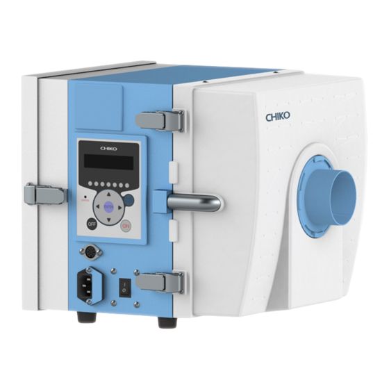
第 2 章 各部の名称 第 2 章 各部の名称 2.1 付属品 ① ② ③ ④ ⑤ ⑥ 100-115V 仕様 220-230V 仕様 ⑦ ⑧ 番号 名称 働き 数量 ① 1 次フィルタ 粉塵を収集・吸着します。 ② 2 次フィルタ 電気部品を粉塵から守ります。 ③ 排気フィルタ 排気をクリーンにします。 ④ 排気 HEPA フィルタ 排気をクリーンにします。(-V1 仕様のみ)... -
Page 9: 装置本体
第 2 章 各部の名称 2.2 装置本体 日 本 語 2.2.1 CBA-080AT3-HI-UL1, UL2 / CBA-500AT3-HI-UL1, UL2 ① ② ⑦ ③ ④ ⑥ ⑤ 番号 名称 働き ① 排気口扉 排気フィルタを収納しています。 ② AT3 パネル(操作パネル) 本機を操作します。 ③ リモートコネクタ リモートケーブル(別売)を接続します。 ④ 電源コネクタ 電源ケーブルを接続します。 ⑤ 主電源スイッチ... -
Page 10: Cba-1200At3-Hi-V1-Ul2
第 2 章 各部の名称 2.2.2 CBA-1200AT3-HI-V1-UL2 ⑨ ① ② ③ ⑧ ④ ⑦ ⑤ 番号 名称 働き ① 排気口扉 排気フィルタを収納しています。 ② AT3 パネル(操作パネル) 本機を操作します。 ③ リモートコネクタ リモートケーブル(別売)を接続します。 ④ 電源コネクタ 電源ケーブルを接続します。 ⑤ 主電源スイッチ 本機の電源の入切を行います。 ⑥ 吸気側フィルタケース 1 次、2 次フィルタを収納しています。 ⑦ 吸込み口(脱着フランジ) 吸気ダクトを接続します。... -
Page 11: At3 パネル
第 2 章 各部の名称 2.3 AT3 パネル 日 本 語 ① ② ③ ④ ⑨ ⑤ ⑤ ⑧ ③ ⑥ ⑦ 番号 名称 働き 有機 EL(OLED) 運転状態や各種設定内容を表示します。 ① ディスプレイ エラー・警告発生時は、エラー・警告 No.を表示します。 ② 能力レベルランプ 能力レベルを緑色のランプで表示します。(レベル 1~7) 停止中、運転中は、ディスプレイの表示内容を切り替えます。 「2.4 ディスプレイ表示」(10 ページ) ③ ↑/↓ボタン... -
Page 12: ディスプレイ表示
第 2 章 各部の名称 2.4 ディスプレイ表示 2.4.1 モードについて 通常モード モードセレクトモード 主電源スイッチ 停止中 ページ モードセレクトボタン 初期圧登録クリア ページ OFF ボタン ON ボタン OFF ボタン 3 秒押し 初期圧登録 運転中 ページ ENTER ボタン 3 秒押し 2.4.2 停止中の表示 ↑/↓ボタンで表示を切り替えることができます。 Ver*.** ID.** プログラムバージョン、RS485 通信用局番 Battery ***% 電池残量... -
Page 13: 運転中の表示
第 2 章 各部の名称 2.4.3 運転中の表示 日 ↑/↓ボタンで表示を切り替えることができます。 本 語 **.**kPa 外部圧 **.**kPa 吸込圧 **.**kPa 差圧 **.**kPa 排気圧 Blower ***.*℃ ブロア周辺温度 モータ回転数 Motor *****rpm 現在運転中のモータの回転数を表示します。 積算稼働時間(リセット可) Runtime ******h リセット後からの稼働時間を表示します。 ページ 積算稼働時間リセットモード( ) 実働時間(リセット不可) Total ******h トータルの稼働時間を表示します。 CMN604-003... -
Page 14: 第 3 章 運転
第 3 章 運転 第 3 章 運転 3.1 運転前の準備 3.1.1 設置 ■ 設置場所 使用上安全および本機の性能を十分に発揮させるため、下記の条件を満たす場所に設置してください。 項 目 内 容 周 囲 温 度 0℃~+40℃の範囲 周 囲 湿 度 80%RH 以下の範囲(結露のないこと) 雰 囲 気 屋内(直射日光が当たらないこと)、腐食性ガス・引火性ガス・オイルミスト・粉塵のないこと ■ ボタン電池絶縁シートの取り外し ボタン電池の絶縁シートを取り外す際には、通電状態で行ってください。 本機を使用する前にボタン電池の絶縁シート 吸気側フィルタケース パッチン錠 を取り外してください。... -
Page 15: 配線・配管
第 3 章 運転 3.1.2 配線・配管 日 本 ■ 配線 語 • 接続は確実に行い、ケーブルを無理に曲げたり、引っ張ったりしないでください。 火災・感電の原因になります。 警 告 • 本機の仕様と異なる電源で使用しないでください。 • アース線は必ず接続して使用してください。 • 電圧低下の原因になりますので、タコ足配線にしないでください。 注 意 電圧が降下すると正常に動作しなくなり、故障の原因になります。 本機の電源は、単相電源です。 供給電圧の許容範囲は、±10%です。 電源コードの本体差し込みプラグを本機の電源コネクタに接続します。 電源コードの電源側を電源に接続します。 ■ 配管 脱着フランジを右にしっかり回して吸気口に取り 付けます。 吸気配管(別途ご準備)を脱着フランジに接続し ます。 脱着フランジ • 適切な配管で運転してください。 重 要 配管はできるだけ短くし、配管口径は狭くしすぎないでください。... -
Page 16: 初期圧登録
第 3 章 運転 3.3 初期圧登録 初期登録した差圧からフィルタ目詰まりによる風量低下を判定し、風量不足(WARN4)としてお知らせします。 次の手順で、初期圧力を登録してください。 本機を配線、配管します。 任意の能力で運転を開始します。 ENTER ボタンを 3 秒間長押しします。 ディスプレイに“Initial DP Get Y”と表示され、初期圧力の更新登録を実施するか確認されます。 更新登録を実施する場合は ENTER ボタンを押します。 初期圧力の取得動作を開始します。 実施しない場合は、MODE SELECT ボタンを押すと通常動作に戻ります。 能力レベル 1 から 7 まで順番に運転し、各能力レベルの差圧を自動取得します。 初期圧力の取得動作中は、ディスプレイに“Initial DP Check”と「能力レベルと差圧」が交互に表示されま す。 登録が完了すると、ディスプレイに“Initial DP Entry”と表示されて通常動作に戻ります。 • フィルタが必ず新品の状態で行ってください。 • 初期圧力登録後、配管を変えた場合やフィルタを全て交換された場合(排気フィルタ除 重... -
Page 17: 第4章 各種設定(モードセレクトモード
第 4 章 各種設定(モードセレクトモード) 第4章 各種設定(モードセレクトモード) 日 本 語 4.1 モードセレクトモードでの画面遷移 停止中に MODE SELECT ボタンを押すとモードセレクトモードに移行します。 ↑/↓ボタンで設定項目を切り替えます。 ( ページ) 通信フォーマット設定モード [Com Setting] 風量不足お知らせタイミング設定モード [Volume Down ST] ( ページ) [Other Setting] ( ページ) その他の設定モード エラー履歴モード ( ページ) [Error Data] 4.2 通信フォーマット設定モード(通信機能装備時) シリアル通信フォーマットの以下の項目を設定します。 設定した内容は主電源スイッチでの再起動後に有効になります。... -
Page 18: 風量不足お知らせタイミング設定モード
第 4 章 各種設定(モードセレクトモード) 終了する場合は MODE SELECT ボタンを押して通常モードに戻ります。 4.3 風量不足お知らせタイミング設定モード 風量不足警告(WARN4)を表示させるタイミングを任意で変更できます。 モードセレクトモードに移行します。 ↑/↓ボタンを押して風量不足お知らせタイミング設定モード(“Volume Down ST”)に移行します。 ENTER ボタンを押します。 現在の設定内容が表示されます。 標準出荷設定値は 50%で、“3:Down to 50%”が表示されます。 ↑/↓ボタンを押して 30%~70%の間で選択します。 設定値を下げると風量不足お知らせのタイミングが遅くなり、設定値を上げると早くなります。 ENTER ボタンを押して設定内容を決定します。 終了する場合は MODE SELECT ボタンを押して通常モードに戻ります。 4.4 その他の設定モード 以下の項目を設定します。 • 日付と時刻の設定 「4.4.1 時刻合わせモード」(16 ページ) • 積算稼働時間のリセット 「4.4.2 積算稼働時間リセットモード」(17 ページ)... -
Page 19: 積算稼働時間リセットモード
第 4 章 各種設定(モードセレクトモード) ENTER ボタンを押します。 日 日付の設定画面になります。 本 ↑/↓ボタンを押して数値を変更します。 語 ENTER ボタンを押して数値を決定します。 年、月、日の順に設定します。 日付が設定されると、時刻の設定画面になります。 ↑/↓ボタンを押して数値を変更します。 ENTER ボタンを押して数値を決定します。 時、分、秒の順に設定します。 終了する場合は、MODE SELECT ボタンを押して通常モードに戻ります。 4.4.2 積算稼働時間リセットモード 積算稼働時間(Runtime)をリセットします。 モードセレクトモードに移行します。 ↑/↓ボタンを押してその他の設定モード(“Other Setting”)に移行します。 ENTER ボタンを押します。 “Time Adjust”が表示されます。 ↑/↓ボタンを押して、表示を“[Runtime Reset]”にします。 ENTER ボタンを押します。 “Reset Runtime Y”と表示され、積算稼働時間をリセットするか確認されます。 リセットする場合は ENTER ボタンを押してください。 4.4.3 設定値リセットモード... -
Page 20: 第 5 章 保守・点検
第 5 章 保守・点検 第 5 章 保守・点検 • 保守・点検時は必ず電源を切り、コンセントからプラグを抜いて、電路遮断を行っ 注 意 てください。 5.1 フィルタの交換 目詰まりした場合、「WARN2」の警告が表示されますので、1 次フィルタを交換してください。 また、1次フィルタを交換しても、「WARN2」表示が消えないときは、2 次フィルタを交換してください。 5.1.1 1 次フィルタの交換 • 1 次フィルタの交換は、吸気側フィルタケースを開くことができる十分なスペースがある場 重 要 所で行ってください。 吸気側フィルタケースのパッチン錠 吸気側フィルタケース パッチン錠 (2 ヶ所)を外します。 吸気側フィルタケースを開け、2 次フィルタ を取り外します。 • 2 次フィルタが取り外しにくい場合は 吸気側フィルタケースと 2 次フィルタ のスキマ(左右)にマイナスドライバ... -
Page 21: 次フィルタの交換
第 5 章 保守・点検 5.1.2 2 次フィルタの交換 日 本 • 2 次フィルタの交換は、吸気側フィルタケースを開くことができる十分なスペースがある場 語 重 要 所で行ってください。 吸気側フィルタケースのパッチン錠 吸気側フィルタケース パッチン錠 (2 ヶ所)を外します。 吸気側フィルタケースを開け、2 次フィルタ を取り外します。 • 2 次フィルタが取り外しにくい場合は 吸気側フィルタケースと 2 次フィルタ のスキマ(左右)にマイナスドライバ メ を差し込んで取り外してください。 モ • 吸気側フィルタケースは、本体から 取り外すこともできます。 2 次フィルタ 新しい 2 次フィルタを取り付けます。 吸気側フィルタケースを閉じ、パッチン錠(2 ヶ所)で固定します。... -
Page 22: モータ冷却用排気フィルタの交換(Cba-1200At3-Hi-V1-Ul2 のみ
第 5 章 保守・点検 5.1.4 モータ冷却用排気フィルタの交換 (CBA-1200AT3-HI-V1-UL2 のみ) 天面のネジ(4 個)を緩め、モータ冷却口カ ネジ モータ冷却口カバー バーを取り外します。 ネジ 新しいモータ冷却用排気フィルタに交換し モータ冷却用排気フィルタ ます。 モータ冷却口カバーを元通りに取り付けます。... -
Page 23: ボタン電池の交換
第 5 章 保守・点検 5.2 ボタン電池の交換 日 本 語 • 本機で使用しているボタン電池のケースは、CR2477 サイズ用です。 CR2477 以外のボタン電池は使用しないでください。 注 意 • 電池の交換は、本体を通電した状態で行ってください。 本体を通電せずに電池を交換すると著しく電池が消耗することがあります。 本体を通電して下さい。 電池カバー 吸気側フィルタケースを開きます。 電池カバーのネジ(2 個)を外し、電池カバ ーを取り外します。 ネジ 爪を右に押し、ボタン電池を取り外します。 ボタン電池 爪 新しいボタン電池に交換します。 電池カバーを元通りに取付けます。 本体の電源を遮断して下さい。 5.3 日常点検 点検項目 頻 度 点検内容 フィルタケース 運転前 完全に閉じているか... -
Page 24: エラー・警告
第 5 章 保守・点検 5.5 エラー・警告 本機には、エラー・警告が発生すると異常ランプを点灯(点滅)させ、ディスプレイに表示データとエラーNo.を交 互に表示する自己診断機能があります。 「5.5.2 」(23 ページ) 表示されるエラー・警告の内容については エラー・警告一覧 を参照してください。 「5.6 」(24 ページ) 自己診断されない故障等については、 故障と思ったら を参照してください。 5.5.1 エラー・警告の処置方法 本機の自己診断機能によりエラー・警告が発生した場合は、以下の操作を行いエラー・警告を解除してください。 説明用の画面は例として記載しています。 エラー・警告が発生すると、異常ランプが点灯 ????? (表示データ) (点滅)しディスプレイに表示データとエラーNo. が交互に表示されます。 交互に表示 複数のエラー・警告が発生しているときは、優 (エラーNo.) ERR04 先順位の高いものが表示されます。 MODE SELECT ボタンを押し、エラー履歴モー 2:ERR04 ドに移行します。 複数のエラー・警告が発生しているときは、エ 優先順位の高いエラーNo. -
Page 25: エラー・警告一覧
第 5 章 保守・点検 5.5.2 エラー・警告一覧 日 本 優先 エラー・警告 異常 本機の エラーNo. 内容 方法 語 順位 名 ランプ 動作 「5.6 故障と思ったら」の②の モータの回転数が下が 運転 対策方法に従って処置を行 ERR03 回転数異常 っている(または停止し 点滅 継続 ってください。 ている) 24 ページ ( ) 「5.6 故障と思ったら」の②の 高 ブロア周辺温度が異常 対策方法に従って処置を行... -
Page 26: 故障と思ったら
第 5 章 保守・点検 5.6 故障と思ったら 番号 故障現象 原 因 対策方法 電源が ON になってい 電源を ON にする。 有機 EL ディスプレイが ない ① 表示しない ヒューズが切れている 修理を依頼してください。 モータ故障を起こして 修理を依頼してください。 いる モータ交換になります。 [1] 排気口/吸引口が塞がれていないか確認 する。 [2] 定格電圧を確認する。 [3] タコ足配線になっていないか確認する。 [4] フィルタの目詰まりや吸込み温度によりモ ータが過熱していないか確認する。 過負荷・異常温度によ り、停止した... -
Page 27: 第6章 便利な使い方(オプション
第 6 章 便利な使い方(オプション) 第6章 便利な使い方(オプション) 日 本 語 6.1 リモートケーブル 6.1.1 標準接続図 CMN604-003... - Page 28 第 6 章 便利な使い方(オプション) ■ 接続例 ● ①、④ピン(入力) 電圧を印加しないでください。 参考回路 ● ②ピン(アナログ出力) 出力電圧:1~5V±0.2V 計測器等 参考回路 ● ③、⑤、⑥ピン(オープンコレクタ出力) 定格を超えないよ うに保護回路を追 加してください。 ③または⑤ または⑥ピン 参考回路 推奨 DC 電圧・電流:最大定格の 1/2 以下 ● ⑦ピン(入力) 参考回路...
-
Page 29: ピンアサイン
第 6 章 便利な使い方(オプション) 6.1.2 ピンアサイン 日 本 ピン 線色 信号名称 内 容 語 番号 黒 ① 運転入力信号* ④と⑧を短絡後、①を短絡して運転を開始します。 ④と⑧を短絡してリモート操作に移行させます。 赤/白 ④ 遠隔操作切替信号* 短絡すると AT3 パネルの通常操作はできなくなりま 遠隔信号 す。 (入力) ⑦と⑧の間で、0~5V の電圧を印加することで能力 黄 ⑦ 能力レベル変更* レベルを変更することができます。 黄/白 ⑧ ― 現在の運転圧力を出力します。 黒/白 ②... -
Page 30: リモート操作
オプションの通信ボードセット(型式:RS-485 又は RS-EN)を使用する事で、運転 ON/OFF や、フィルタ目詰ま り等の情報を取り出す事が可能です。 6.2.1 RS485 通信 設定方法は、「4.2 通信フォーマット設定モード(通信機能装備時)」を参照してください。 「4.2 通信フォーマット設定モード(通信機能装備時)」(15 ページ) 6.2.2 イーサネット 詳細については、別途購入されたイーサネットの取扱説明書を参照してください。 6.3 脱着フランジ ご使用の環境に応じて吸込み口径の変更が必要な場合は、工具なしでフランジを交換することができます。 交換可能なフランジ径 フランジ径(mm) 型式 φ38 φ50 φ65 φ75 CBA-080AT3-HI-UL1, FRJ-D-38-35-92 FRJ-D-50-35-92 FRJ-D-65-35-92 ― CBA-500AT3-HI-UL1, FRJ-D-38-35-108 FRJ-D-50-35-108 FRJ-D-65-35-108 FRJ-D-75-35-108 CBA-1200AT3-HI-V1- FRJ-D-38-35-108 FRJ-D-50-35-108 FRJ-D-65-35-108 FRJ-D-75-35-108 の脱着フランジは出荷時に標準で付属しています。... -
Page 31: 第7章 付録
第 7 章 付録 第7章 付録 日 本 語 7.1 仕様 モータ 最大 最大 型式 電圧 *2 電流値 周波数 騒音値* 質量 定格出力 吸込風量 吸込静圧 100-115V CBA-080AT3-HI-(V1-)UL1 7.6A 単相 450W 50/60Hz 1.9m /min 9.3kPa 58-70dB 10.0kg 220-230V CBA-080AT3-HI-(V1-)UL2 4.3A 単相 100-115V CBA-500AT3-HI-(V1-)UL1 7.9A 単相... -
Page 32: 電気回路図
第 7 章 付録 7.3 電気回路図 7.3.1 CBA-080AT3-HI-UL1, UL2 これらの基板は説明 のため反体面を透視 した状態で記載して 7.3.2 CBA-500AT3-HI-UL1, UL2... -
Page 33: Cba-1200At3-Hi-V1-Ul2
第 7 章 付録 7.3.3 CBA-1200AT3-HI-V1-UL2 日 本 語 CMN604-003... - Page 34 ■保証と責任の範囲 ●保証期間 正常な使用状態で、故障または損傷が生じた場合には、出荷後 12 ヶ月間は無料で修理いたします。 ただし、7.2 消耗品リストに記載の消耗品は除きます。 「7.2 消耗品リスト」(29 ページ) 下記のような場合は保証期間内でも有償とさせていただきます。 • 本書に記載されている注意事項を順守しなかった場合に発生した故障または損傷の場合 • 本書に記載されている使用環境以外での使用による故障または損傷の場合 • 弊社および弊社指定の販売店以外で修理・改造・分解等をした場合 • 使用中に生じたキズ、汚れなどの外観上の変化の場合 • 消耗品・付属品の交換および弊社指定以外の部品を使用した場合 • お買い上げ後の落下、および運送上の事故による故障または損傷の場合 • 火災、塩害、ガス害、地震、風水害、落雷、電圧異常およびその他の天変地異を原因とする故障または損 傷の場合 ●修理について 出張修理をご希望の場合、出張料金は、保証期間内外を問わず有料となります。 修理の都合により、修理時に改良部品を使用する場合がございます。 本機の故障による損害、データの抹消による損害、その他本機の使用により生じた損害について、弊社は一 切その責任を負いかねますので、ご了承ください。 ■お買い上げメモ 型 式 製造番号 購入年月日 運転開始日 年 月 お客様お名前 住所...
- Page 35 Other Precautions ........................36 Safety Label Locations ......................37 Chapter 2 Components Identification ................38 Accessories ..........................38 Device Body ..........................39 CBA-080AT3-HI-UL1, UL2 / CBA-500AT3-HI-UL1, UL2 ........... 39 2.2.1 CBA-1200AT3-HI-V1-UL2 ....................40 2.2.2 AT3 Panel ..........................41 Display Indications ........................42 About Modes ........................
- Page 36 RS485 Communication ..................... 60 6.2.1 Ethernet ..........................60 6.2.2 Removable Flange ........................60 Chapter 7 Appendix ......................61 Specifications ........................... 61 Consumables List ........................61 Electrical Diagram ........................62 CBA-080AT3-HI-UL1, UL2 ....................62 7.3.1 CBA-500AT3-HI-UL1, UL2 ....................62 7.3.2 CBA-1200AT3-HI-V1-UL2 ....................63 7.3.3...
-
Page 37: Chapter 1 Product Usage Precautions
Chapter 1 Product Usage Precautions Chapter 1 Product Usage Precautions 1.1 Safety Notations This instruction manual describes usage precautions with the below listed symbols. Be sure to read the instructions. Symbol Meaning Indicates a hazardous situation which, if not avoided, could result in personal death or WARNING serious injury. -
Page 38: Precautions For Operation
Chapter 1 Product Usage Precautions 1.4 Precautions for Operation • Do not suck the following substances: Flammable substances ... Gasoline, thinner, benzine, kerosene, paints, etc. Explosive dusts ... Aluminum, magnesium, titanium, zinc, epoxy, etc. Sparky dust ....Dust containing sparks from high-speed cutting machine, grinder, welding machine, etc. -
Page 39: Safety Label Locations
Chapter 1 Product Usage Precautions 1.6 Safety Label Locations “Do not disassemble” label High voltage Warning label High temperature Warning label MET label Nameplate Attention label Fuse rated label Attention label High voltage High temperature “Do not Nameplate warning label warning label disassemble”... -
Page 40: Chapter 2 Components Identification
Chapter 2 Components Identification Chapter 2 Components Identification 2.1 Accessories ① ② ③ ④ ⑤ ⑥ 100-115V version 220-230V version ⑦ ⑧ Name Function Qty. Primary filter Collects/adsorbs dust. ① Secondary filter Protects electrical parts from dust. ② Exhaust filter Cleans exhaust. -
Page 41: Device Body
Chapter 2 Components Identification 2.2 Device Body 2.2.1 CBA-080AT3-HI-UL1, UL2 / CBA-500AT3-HI-UL1, UL2 ① ② ⑦ ③ ④ ⑥ ⑤ Name Function Exhaust port door Contains an exhaust filter. ① ② AT3 panel (operation panel) Operates the device. Remote connector Connects a remote cable (optional). -
Page 42: Cba-1200At3-Hi-V1-Ul2
Chapter 2 Components Identification 2.2.2 CBA-1200AT3-HI-V1-UL2 ⑨ ① ② ③ ⑧ ④ ⑦ ⑤ Name Function Exhaust port door Contains an exhaust filter. ① AT3 panel (operation panel) Operates the device. ② Remote connector Connects a remote cable (optional). ③ Power connector Connects the power cable. -
Page 43: At3 Panel
Chapter 2 Components Identification 2.3 AT3 Panel ① ② ③ ④ ⑨ ⑤ ⑤ ⑧ ③ ⑥ ⑦ Name Function Organic EL Displays the operating status and various settings. ① (OLED) display Displays an error or warning number in case of an error or warning. Suction power Green lamps indicate a suction power level (1 to 7). -
Page 44: Display Indications
Chapter 2 Components Identification 2.4 Display Indications 2.4.1 About Modes Normal mode Main power During stoppage Page 47 MODE SELECT button switch ON OFF button Page 46 OFF button ON button Held down for 3 sec During operation Page 46 ENTER button Held down for 3 sec 2.4.2 Indications During Stoppage... -
Page 45: Indications During Operation
Chapter 2 Components Identification 2.4.3 Indications During Operation The Up/Down arrow buttons cycle through indications. **.**kPa External pressure **.**kPa Suction pressure **.**kPa Differential pressure **.**kPa Exhaust pressure Blower ***.*°C Temperature around blower Motor rotational frequency Motor *****rpm Indicates the rotational frequency of the currently running motor. Accumulated run time (resettable) Runtime ******h... -
Page 46: Chapter 3 Operation
Chapter 3 Operation Chapter 3 Operation 3.1 Start-up Preparation 3.1.1 Installation ■ Installation location To ensure operating safety and deliver the full performance of the device, install the device in a location that meets the following conditions: Item Description Ambient temperature 0°... -
Page 47: Operation
Chapter 3 Operation 3.1.2 Wiring and Piping ■ Wiring • Perform wiring firmly, without bending or pulling cables with excessive force. Fire or electric shock may result. WARNING • Ensure that the power supply conforms to the specifications of the device. •... -
Page 48: Registering Initial Pressures
Chapter 3 Operation 3.3 Registering Initial Pressures Air volume reduction due to filter clogging is judged based on a registered initial differential pressure and indicated as low air volume (WARN4). Register initial pressures through these steps: Perform the wiring and piping of the device. Start the device at a desired suction power level. -
Page 49: Chapter 4 Configuring Settings (Mode Select Mode)
Chapter 4 Configuring Settings (MODE SELECT Mode) Chapter 4 Configuring Settings (MODE SELECT Mode) 4.1 Screen Transitions in MODE SELECT Mode To move to the MODE SELECT mode, press the MODE SELECT button during stoppage. The Up/Down arrow buttons cycle through parameters. Communication format setting mode [Com Setting] (... -
Page 50: Air Volume-Down Alert Timing Setting Mode
Chapter 4 Configuring Settings (MODE SELECT Mode) The setting screen appears. Press the Up/Down arrow buttons to select the desired setting. Press the ENTER button to determine the setting. To exit this mode, press the MODE SELECT button to return to normal mode. 4.3 Air Volume-Down Alert Timing Setting Mode This mode allows for changing the timing for displaying an air volume-down warning (WARN4) as desired. -
Page 51: Accumulated Run Time Reset Mode
Chapter 4 Configuring Settings (MODE SELECT Mode) Press the ENTER button. The date setting screen appears. Press the Up/Down arrow buttons to change the value. Press the ENTER button to determine the value. Set the value in this order: year, month, and day. After the date is set, the time setting screen appears. -
Page 52: Chapter 5 Maintenance And Checkup
Chapter 5 Maintenance and Checkup Chapter 5 Maintenance and Checkup • Before starting maintenance and checkup, be sure to break the electrical CAUTION circuit by turning off the power supply and disconnecting the plug from the power outlet. 5.1 Replacing Filters If clogging occurs, a “WARN2”... -
Page 53: Replacing The Secondary Filter
Chapter 5 Maintenance and Checkup 5.1.2 Replacing the Secondary Filter • The secondary filter should be replaced in an area large enough to open the suction- IMPORTANT side filter case. Release the two snap locks for suction-side Suction-side filter case Snap locks filter case. -
Page 54: Replacing The Motor Cooling Exhaust Filter (Cba-1200At3-Hi-V1-Ul2 Only)
Chapter 5 Maintenance and Checkup 5.1.4 Replacing the Motor Cooling Exhaust Filter (CBA-1200AT3-HI-V1-UL2 Only) Loosen the four screws from the top and Screws Motor cooling port cover remove the motor cooling port cover. Screws Replace with a new motor cooling exhaust Motor cooling exhaust filter filter. -
Page 55: Replacing The Button Battery
Chapter 5 Maintenance and Checkup 5.2 Replacing the Button Battery • The button battery case used in the device is for CR2477 size. Do not use button batteries other than CR2477. CAUTION • Turn on the electricity of the device while replacing the battery, or it will cause a huge consumption of the battery. -
Page 56: Errors/Warnings
Chapter 5 Maintenance and Checkup 5.5 Errors/Warnings If an error/warning occurs, the self-diagnosis function built-in the device lights (flashes) the ERROR lamp and shows display data and error number alternately on the display. For a description of errors/warnings displayed, see “5.5.2 Error/Warning Table” (page 55). For faults and conditions not covered by self-diagnosis, see “5.6 Troubleshooting”... -
Page 57: Error/Warning Table
Pressure error low pressure for more Stop in “5.6 Troubleshooting” than preset period. Page 56). F-RAM write Remains ERR07 Cannot write to F-RAM. Flashing Contact CHIKO AIRTEC. error operational Communication BCC judgment Remains ERR08 Flashing Contact CHIKO AIRTEC. error mismatch operational Follow the remedies for ②... -
Page 58: Troubleshooting
“5.1 Replacing Filters” (page 50) Replace filters. Clogged filter “5.1 Replacing Filters” (page 50) Foreign matter Call for repair. Odd noise or vibration entered in blower. ⑤ from motor Broken motor bearing Call for repair. ※For other phenomena, contact CHIKO AIRTEC. -
Page 59: Chapter 6 Useful Utilization (Optional)
Chapter 6 Useful Utilization (Optional) Chapter 6 Useful Utilization (Optional) 6.1 Remote Cable 6.1.1 Standard Connection Diagram CMN604-003 Original instructions... - Page 60 Chapter 6 Useful Utilization (Optional) ■ Connection examples ● Pins ① and ④ (input) Device side Customer side Do not apply Pin ① or ④ voltage. Pin ⑧ Reference circuit ● Pin ② (analog output) Device side Customer side Output voltage: 1 to 5 V 0.2 V Measuring instrument, etc.
-
Page 61: Pin Assignments
Chapter 6 Useful Utilization (Optional) 6.1.2 Pin Assignments Wire color Pin # Signal name Description Operation input With ④ and ⑧ short-circuited, ① is short- Black ① signal circuited to start operation. ④ and ⑧ are short-circuited to start remote Remote control operation. -
Page 62: Communication Function
Flanges can be replaced without using tools if a different diameter of suction port is required to suit particular operating environments. Replaceable flange diameters Flange diameter (mm) Model φ38 φ50 φ65 φ75 CBA-080AT3-HI-UL1, FRJ-D-38-35-92 FRJ-D-50-35-92 FRJ-D-65-35-92 ― CBA-500AT3-HI-UL1, FRJ-D-38-35-108 FRJ-D-50-35-108 FRJ-D-65-35-108... -
Page 63: Chapter 7 Appendix
Chapter 7 Appendix Chapter 7 Appendix 7.1 Specifications Max. Motor rated Current Frequen Noise Max. suction Model Voltage* suction Mass static pressure output value value* volume 100 to 115 V CBA-080AT3-HI-(V1-)UL1 7.6 A single phase 450 W 50/60 Hz 1.9 m /min 9.3 kPa 58 to 70 dB... -
Page 64: Electrical Diagram
Chapter 7 Appendix 7.3 Electrical Diagram 7.3.1 CBA-080AT3-HI-UL1, UL2 これらの基板は説明 のため反体面を透視 した状態で記載して 7.3.2 CBA-500AT3-HI-UL1, UL2... -
Page 65: Cba-1200At3-Hi-V1-Ul2
Chapter 7 Appendix 7.3.3 CBA-1200AT3-HI-V1-UL2 CMN604-003 Original instructions... - Page 66 Travel expenses for on-site service will be chargeable whether within or outside the warranty period. For repair reasons, improved parts may be used for repair. CHIKO AIRTEC will not be liable for any damage resulting from use of this device, such as damage caused by failure of the device or by erasion of data.
- Page 67 MEMO...
- Page 68 チコーエアーテック株式会社 CHIKO AIRTEC CO.,LTD. 〒562-0012 大阪府箕面市白島 2-27-24 2-27-24,Hakushima, Minoh, Osaka 562-0012, Japan TEL (81) 072-720-5151 FAX (81) 072-720-5133 URL http://chiko-airtec.jp/...
Need help?
Do you have a question about the CBA-080AT3-HI-UL1 and is the answer not in the manual?
Questions and answers