Table of Contents
Advertisement
Quick Links
• 取扱説明書(以下、本書といいます)の『製品使用上のご注意』の内容をよく理解し、本書をよく読んでか
ら操作してください。
Please understand well the contents of "Cautions on Product Use" of Instruction Manual
(hereinafter referred to as "this manual"), and operate it after often reading this manual.
• 本書はいつでも使用できるよう、大切に保管してください。
Please keep this manual carefully to be able to use it at any time.
チコーエアーテック株式会社
CHIKO AIRTEC CO., LTD.
ご使用者様用
中型集塵機
Dust Collector
オペレータ用取扱説明書
Operators Instruction Manual
Document No. CMN209-010-01
型式/MODELS
CMP-2500AT3-A
CMP-2500AT3-A-V1
日
本
語
Advertisement
Chapters
Table of Contents

Related Manuals for Chiko CMP-2500AT3-A


Summary of Contents for Chiko CMP-2500AT3-A
- Page 1 Please understand well the contents of "Cautions on Product Use" of Instruction Manual (hereinafter referred to as “this manual”), and operate it after often reading this manual. • 本書はいつでも使用できるよう、大切に保管してください。 Please keep this manual carefully to be able to use it at any time. チコーエアーテック株式会社 CHIKO AIRTEC CO., LTD.
- Page 2 揮できますよう正しいお取扱いをお願いします。 We greatly appreciate that you have purchased our CMP Series. CHIKO AIRTEC CO., LTD. is working to achieve clean air with compact equipment while utilizing “air technology” effectively. The CMP Series is an energy-saving-type clean box that realizes “air technology” in a compact body.
-
Page 3: Table Of Contents
目 次 第 1 章 製品使用上のご注意 ..........................2 1.1 安全に関する表記 ..................................2 1.2 運転時のご注意 ..................................2 1.3 その他のご注意 ..................................3 1.4 危険シールの貼付位置 ................................4 第 2 章 各部の名称 ..............................5 2.1 付属品 ......................................5 2.2 装置本体 ......................................6 2.2.1 CMP-2500 AT3-A(-V1) ............................... 6 2.3 AT3 パネル... -
Page 4: 第 1 章 製品使用上のご注意
第 1 章 製品使用上のご注意 第 1 章 製品使用上のご注意 1.1 安全に関する表記 この取扱説明書には、使用時の注意事項が下記の記号とともに記載されています。 必ずお読みください。 記 号 意 味 正しく使用しない場合、取扱者が死亡または重傷を負う危険性がある注意事項が記載され 警 告 ています。 正しく使用しない場合、取扱者が傷害を負う危険性や本装置を損傷する恐れがある注意 注 意 事項が記載されています。 行ってはいけない「禁止」の内容です。 必ず実行する「強制」の内容です。 1.2 運転時のご注意 • 次の物質は吸引しないでください。 引火性物質 ..... ガソリン・シンナー・ベンジン・灯油・塗料など。 爆発性粉塵 ..... アルミニウム・マグネシウム・チタン・亜鉛・エポキシなど 火花を含んだ粉塵 ..高速切断機・グラインダー・溶接機などから発生する火花 を含んだ粉塵。 火種... -
Page 5: その他のご注意
第 1 章 製品使用上のご注意 1.3 その他のご注意 • 本機を分解・改造しないでください。 感電・けがの原因になります。 内部の点検や修理はお買い上げになった販売店にご連絡ください。 • お手入れに、ベンジン・シンナー・アルコール・漂白剤・原液の洗剤を使わないで 警 告 ください。 • 設置、接続、運転、操作、点検、故障診断の作業は、取扱説明書の内容に従 い、適切に行ってください。 誤った作業を行うと、火災・感電・けがなどの事故の原因になります。 • 廃棄する場合は、産業廃棄物として適切に処分してください。 注 意 CMN209-010-01... -
Page 6: 危険シールの貼付位置
第 1 章 製品使用上のご注意 1.4 危険シールの貼付位置 分解禁止シール リモートコネクタシール ネームプレート (UL 仕様のみ) MET 認証ラベル コミュニケーションボードシール (UL 仕様のみ) (UL 仕様のみ) 高温警告シール 高電圧警告シール 注意喚起シール (UL 仕様のみ) レギュレータ注記シール 高電圧警告シール 高温警告シール ネームプレート リモートコネクタシール コミュニケーションボードシール レギュレーター注記シール (UL 仕様のみ) (UL 仕様のみ) MET 認証ラベル 注意喚起シール 分解禁止シール (UL 仕様のみ) (UL 仕様のみ) -
Page 7: 第 2 章 各部の名称
第 2 章 各部の名称 第 2 章 各部の名称 2.1 付属品 ① ② ③ ④ ⑤ ⑥ ⑦ 番号 名称 働き 数量 ① 1 次フィルタ 粉塵を収集します。 ② 排気 HEPA フィルタ 排気をクリーンにします。(-V1 仕様のみ) ③ フィルタレギュレータ 圧縮空気の圧力を調整します。 ④ ブロア冷却フィルタ ブロアへの冷却吸気をクリーンにします。 ⑤ 取扱説明書 本機の使用方法を説明しています。(本書) ※1 ⑥... -
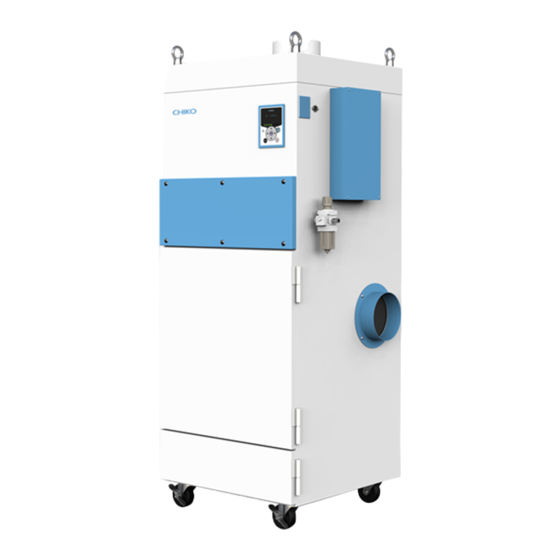
Page 8: 装置本体
第 2 章 各部の名称 2.2 装置本体 2.2.1 CMP-2500AT3-A(-V1) ① ③ ② ④ ⑩ ⑨ ⑤ ⑦ ⑥ ⑧ ⑪ ⑫ 番号 名称 働き ① 排気口 吸気したものを排気します。 ② AT3 パネル(操作パネル) 本機を操作します。 ③ リモートコネクタ リモートケーブル(別売)を接続します。 ④ コミュニケーションボード設置箇所 コミュニケーションボード(別売)を設置します。 ⑤ フィルタレギュレータ設置箇所 フィルタレギュレータ(付属)を設置します。 ⑥... -
Page 9: At3 パネル
第 2 章 各部の名称 2.3 AT3 パネル ① ② ③ ④ ⑨ ⑤ ⑤ ⑧ ③ ⑥ ⑦ 番号 名称 働き 有機 EL(OLED) 運転状態や各種設定内容を表示します。 ① ディスプレイ エラー・警告発生時は、エラー・警告 No.を表示します。 ② 能力レベルランプ 能力レベルを緑色のランプで表示します。(レベル 1~7) 停止中、運転中は、ディスプレイの表示内容を切り替えます。 「2.4 ディスプレイ表示」(8 ページ) ③ ↑/↓ボタン モードセレクトモード時は、設定項目の切り替えと設定する数値データを変更し ます。 「第... -
Page 10: ディスプレイ表示
第 2 章 各部の名称 2.4 ディスプレイ表示 2.4.1 モードについて 通常モード モードセレクトモード 主電源スイッチ 停止中 ページ モードセレクトボタン 初期圧登録クリア ページ OFF ボタン ON ボタン OFF ボタン 3 秒押し 初期圧登録 運転中 ページ ENTER ボタン 3 秒押し パルス制御設定モード ページ モードセレクトボタン 2.4.2 停止中の表示 Ver*.** ID.** プログラムバージョン、RS485 通信用局番... -
Page 11: 運転中の表示
第 2 章 各部の名称 2.4.3 運転中の表示 ↑/↓ボタンで表示を切り替えることができます。 **.**kPa 外部圧 **.**kPa 吸込圧 **.**kPa 差圧 **.**kPa 排気圧 Blower ***.*℃ ブロア周辺温度 モータ回転数 Motor *****rpm 現在運転中のモータの回転数を表示します。 積算稼働時間(リセット可) Runtime ******h リセット後からの稼働時間を表示します。 ページ 積算稼働時間リセットモード( ) 実働時間(リセット不可) Total ******h トータルの稼働時間を表示します。 CMN209-010-01... -
Page 12: 第 3 章 運転
第 3 章 運転 第 3 章 運転 3.1 運転 通電状態にします。 ディスプレイにプログラムバージョンと Ver*.** ID.** RS485 通信用の ID 番号が表示されます。 AT3 パネルの ON ボタンを押します。 装置の運転が開始されます。 異常音がないことと、適切な吸引であること を確認します。 能力レベルランプ ←/→ボタンで吸引レベルを設定します。 能力レベルランプ(1~7)で吸引能力が表示 されます。 ←/→ボタン • 3 分以上のインターバルをおいて、ON/OFF の操作を行ってください。 重 要 3 分未満、特に 30 秒未満の ON/OFF を繰り返すと故障の原因になります。 3.2 初期圧登録... -
Page 13: 日常点検
第 3 章 運転 ● 初期圧登録クリア 停止中に OFF ボタンを 3 秒間長押しします。 ディスプレイに“Initial DP Clr Y”と表示され、登録した初期圧をクリアするか確認されます。 クリアする場合は ENTER ボタンを押します。 クリアしない場合は、MODE SELECT ボタンを押すと通常動作に戻ります。 クリアが完了すると、ディスプレイに“Initial DP Clr”と表示されて通常の停止状態に戻ります。 3.3 日常点検 点検項目 頻 度 点検内容 各扉 運転前 完全に閉じているか 吸込口 運転前 吸込口が閉ざされていないか 排気の状態 1 回/1 日 排気口が閉ざされていないか... -
Page 14: 第 4 章 各種設定(モードセレクトモード
第 4 章 各種設定(モードセレクトモード) 第 4 章 各種設定(モードセレクトモード) 4.1 モードセレクトモードでの画面遷移 停止中に MODE SELECT ボタンを押すとモードセレクトモードに移行します。 ↑/↓ボタンで設定項目を切り替えます。 通信フォーマット設定モード [Com Setting] ( ページ) 風量不足お知らせタイミング設定モード [Volume Down ST] ( ページ) パルス制御設定モード [Pulse Setting] ( ページ) その他の設定モード [Other Setting] ( ページ) エラー履歴モード [Error Data] ( ページ)... -
Page 15: 風量不足お知らせタイミング設定モード
第 4 章 各種設定(モードセレクトモード) ENTER ボタンを押します。 設定画面が表示されます。 ↑/↓ボタンを押して設定内容を選択します。 ENTER ボタンを押して設定内容を決定します。 終了する場合は MODE SELECT ボタンを押して通常モードに戻ります。 4.3 風量不足お知らせタイミング設定モード 風量不足警告(WARN4)を表示させるタイミングを任意で変更できます。 モードセレクトモードに移行します。 ↑/↓ボタンを押して風量不足お知らせタイミング設定モード(“Volume Down ST”)に移行します。 ENTER ボタンを押します。 現在の設定内容が表示されます。 標準出荷設定値は 50%で、“3:Down to 50%”が表示されます。 ↑/↓ボタンを押して 30%~70%の間で選択します。 設定値を下げると風量不足お知らせのタイミングが遅くなり、設定値を上げると早くなります。 ENTER ボタンを押して設定内容を決定します。 終了する場合は MODE SELECT ボタンを押して通常モードに戻ります。 4.4 パルス制御設定モード パルス制御のインターバル時間と、AUTO 有効/無効を設定します。 ■インターバル時間... -
Page 16: その他の設定モード
第 4 章 各種設定(モードセレクトモード) (動作中は、この操作不要で 3 に飛びます。) ENTER ボタンを押します。インターバル時間の確認画面になり、現在の設定内容が表示されます。 ↑/↓ボタンを押すと、AUTO 設定の確認画面になり、現在の設定内容が表示されます。 標準出荷設定値は AUTO 設定【NO】です。 ENTER ボタンを押します。設定画面になります。 ↑/↓ボタンで、※AUTO 設定 Yes/No を選択します。 ENTER ボタンを押して決定します。 終了する場合は、MODE SELECT ボタンを押して通常モードに戻ります。 ※AUTO 設定: WARN4 風量不足判定時に、パルスを打つ設定です。 4.5 その他の設定モード 以下の項目を設定します。 • 積算稼働時間のリセット 「4.5.1 積算稼働時間リセットモード」(14 ページ) • 設定データのリセット 「4.5.2 設定値リセットモード」(14 ページ) 4.5.1 積算稼働時間リセットモード... -
Page 17: エラー履歴モード
第 4 章 各種設定(モードセレクトモード) 4.6 エラー履歴モード 4 件分のエラー履歴を確認することができます。 エラー履歴は主電源スイッチを OFF するとクリアされます。 モードセレクトモードに移行します。 ↑/↓ボタンを押してエラー履歴モードに移行します。 ENTER ボタンを押します。 直近で発生したエラーNo と発生したときの積算稼働時間が表示されます。 ↓ボタンを押すと、新しい順に 4 件分のエラー履歴が表示されます。 終了する場合は、MODE SELECT ボタンを押して通常モードに戻ります。 CMN209-010-01... -
Page 18: 第 5 章 便利な使い方(オプション
第 5 章 便利な使い方(オプション) 第 5 章 便利な使い方(オプション) 5.1 リモートケーブル 5.1.1 標準接続図... - Page 19 第 5 章 便利な使い方(オプション) ■ 接続例 ● ①、④ピン(入力) 電圧を印加しないでください。 参考回路 ● ②ピン(アナログ出力) 出力電圧:1~5V±0.2V 計測器等 参考回路 ● ③、⑤、⑥ピン(オープンコレクタ出力) 定格を超えないよ うに保護回路を追 加してください。 ③または⑤ または⑥ピン 参考回路 推奨 DC 電圧・電流:最大定格の 1/2 以下 ● ⑦ピン(入力) 参考回路 CMN209-010-01...
-
Page 20: ピンアサイン
第 5 章 便利な使い方(オプション) 5.1.2 ピンアサイン ピン 線色 信号名称 内 容 番号 黒 ① 運転入力信号* ④と⑧を短絡後、①を短絡して運転を開始します。 ④と⑧を短絡してリモート操作に移行させます。 赤/白 ④ 遠隔操作切替信号* 短絡すると AT3 パネルの通常操作はできなくなりま 遠隔信号 す。 (入力) ⑦と⑧の間で、0~5V の電圧を印加することで能力 黄 ⑦ 能力レベル変更* レベルを変更することができます。 黄/白 ⑧ ― 現在の運転圧力を出力します。 黒/白 ② 運転圧力信号 アナログ信号:1~5V、インピーダンス:≧4.7kΩ 運転中はHI、目詰まり発生時はLOを出力します。... -
Page 21: リモート操作
第 5 章 便利な使い方(オプション) 5.1.3 リモート操作 • リモート操作で運転 ON/OFF する場合は、④ピンと⑧ピンを短絡させておきます。 ①ピンを短絡→運転 ON ①ピンを短絡しない→運転 OFF 「5.1.2 ピンアサイン」(18 ページ)を参照してください。 • 本機側の操作で運転 ON/OFF して信号を取り出す場合は、④ピンと⑧ピンを短絡させないでください。 「5.1.2 ピンアサイン」(18 ページ)の説明に従い、必要な出力信号を取り出してください。 • リモート操作移行中に本機側で初期圧登録・運転 ON/OFF の操作・能力レベルを変更することはできませ ん。 • 能力レベルを変更する時にレベルが記憶されるため、万が一主電源を切っても前回の能力レベルを記憶し ています。 5.2 通信機能 オプションの通信ボードセット(型式:RS-485 又は RS-EN)を使用する事で、運転 ON/OFF や、フィルタ目詰ま り等の情報を取り出す事が可能です。 5.2.1 RS485 通信... -
Page 22: 第 6 章 付録
6.1 仕様 モータ 最大 最大 騒音値 型式 定格出 電圧 電流値 周波数 吸込静 質量 吸込風量 力 圧 CMP-2500AT3-A 139.0kg AC200- 65~ 2800W 230V 三相 50/60Hz 30 ㎥/min 5.50kPa 69dB 5 CMP-2500AT3-A-V1 142.0kg *1: 騒音値は吸込み口にホースを接続し、本機から 1m 離れて A スケール dB で測定しています。... -
Page 23: 保証と責任の範囲
第 6 章 付録 6.3 保証と責任の範囲 ●保証期間 正常な使用状態で、故障または損傷が生じた場合には、出荷後 12 ヶ月間は無料で修理いたします。 ただし、6.2 消耗品リストに記載の消耗品は除きます。 「6.2 消耗品リスト」(20 ページ) 下記のような場合は保証期間内でも有償とさせていただきます。 • 本書に記載されている注意事項を順守しなかった場合に発生した故障または損傷の場合 • 本書に記載されている使用環境以外での使用による故障または損傷の場合 • 弊社および弊社指定の販売店以外で修理・改造・分解等をした場合 • 使用中に生じたキズ、汚れなどの外観上の変化の場合 • 消耗品・付属品の交換および弊社指定以外の部品を使用した場合 • お買い上げ後の落下、および運送上の事故による故障または損傷の場合 • 火災、塩害、ガス害、地震、風水害、落雷、電圧異常およびその他の天変地異を原因とする故障または損 傷の場合 ●修理について 出張修理をご希望の場合、出張料金は、保証期間内外を問わず有料となります。 修理の都合により、修理時に改良部品を使用する場合がございます。 本機の故障による損害、データの抹消による損害、その他本機の使用により生じた損害について、弊社は一 切その責任を負いかねますので、ご了承ください。 ■お買い上げメモ 型 式 製造番号 購入年月日... - Page 24 第 6 章 付録...
- Page 25 1.4 Safety Label Locations ....................... 26 Chapter 2 Components Identification ................27 2.1 Accessories ..........................27 2.2 Device Body ..........................28 2.2.1 CMP-2500AT3-A(-V1) ....................... 28 2.3 AT3 Panel ........................... 29 2.4 Display Indications ........................30 2.4.1 About Modes ........................30 2.4.2 Indications during Stoppage ....................
-
Page 26: Chapter 1 Product Usage Precautions
Chapter 1 Product Usage Precautions Chapter 1 Product Usage Precautions 1.1 Safety Notations This instruction manual describes usage precautions with the below listed symbols. Be sure to read the instructions. Symbol Meaning Indicates a hazardous situation which, if not avoided, could result in personal death or WARNING serious injury. -
Page 27: Other Precautions
Chapter 1 Product Usage Precautions 1.3 Other Precautions • Do not disassemble or alter the device. Failure to observe can cause electric shock or injury. For internal checkup or repair, contact your dealer. • Do not use benzine, thinner, alcohol, bleach, or undiluted detergent to clean WARNING the product. -
Page 28: Safety Label Locations
Chapter 1 Product Usage Precautions 1.4 Safety Label Locations Name plate Remote connector label (UL specification only) MET label (UL specification only) Communication board label High temperature (UL specification only) warning label High voltage warning label Attention label (UL specification only) Regulator information sticker High voltage... -
Page 29: Chapter 2 Components Identification
Chapter 2 Components Identification Chapter 2 Components Identification 2.1 Accessories ① ② ③ ④ ⑤ ⑥ ⑦ Name Function Qty. Primary filter Collects dust. ① Exhaust HEPA filter Cleans exhaust (-V1 specification only) ② Inverter cooling intake/exhaust filter Protects electric parts from dust ③... -
Page 30: Device Body
Chapter 2 Components Identification 2.2 Device Body 2.2.1 CMP-2500AT3-A(-V1) ① ③ ② ④ ⑩ ⑨ ⑤ ⑦ ⑥ ⑧ ⑪ ⑫ Name Function Exhaust port Expels dust intake. ① AT3 panel (operation panel) Operates the device. ② Remote connector Connects a remote cable (optional). -
Page 31: At3 Panel
Chapter 2 Components Identification 2.3 AT3 Panel ① ② ③ ④ ⑨ ⑤ ⑤ ⑧ ③ ⑥ ⑦ Name Function Organic EL Displays the operating status and various settings. ① (OLED) display Displays an error or warning number in case of an error or warning. Suction power Green lamps indicate a suction power level (1 to 7). -
Page 32: Display Indications
Chapter 2 Components Identification 2.4 Display Indications 2.4.1 About Modes Normal mode During MODE SELECT Main power stoppage Mode MODE SELECT button switch ON Page 34 Clearing registered initial pressures OFF button Page 32 ON button OFF button Held down for 3 sec Registering Initial During Pressures... -
Page 33: Indications During Operation
Chapter 2 Components Identification 2.4.3 Indications during Operation The Up/Down arrow buttons cycle through indications. **.**kPa External pressure **.**kPa Suction pressure **.**kPa Differential pressure **.**kPa Exhaust pressure Blower ***.*℃ Temperature around blower Motor rotational frequency Motor *****rpm Indicates the rotational frequency of the currently running motor. -
Page 34: Chapter 3 Operation
Chapter 3 Operation Chapter 3 Operation 3.1 Operation Turn on the power switch. The display indicates the program Ver*.** ID.** version and the ID for RS485 communication. Press the ON button on the AT3 panel. The device starts operation. Check that abnormal noise is not generated and the suction is appropriate Set a desired suction power level by Performance... -
Page 35: Daily Checkup
Chapter 3 Operation ● Clearing registered initial pressures Hold down the OFF button for three seconds when the device is in stop state. The display shows “Initial DP Clr Y”, prompting confirmation to clear registered initial pressures. To clear them, press the ENTER button. If you do not want to clear them, press the MODE SELECT button to return to normal operation. -
Page 36: Chapter 4 Various Settings(Mode Select Mode)
Chapter 4 Various settings (mode select mode) Chapter 4 Various settings (mode select mode) 4.1 Screen Transitions in MODE SELECT Mode To move to the MODE SELECT mode, press the MODE SELECT button during stoppage. The Up/Down arrow buttons cycle through parameters. Communication Format Setting Mode [Com Setting] (When Equipped with Communication... -
Page 37: Air Volume-Down Alert Timing Setting Mode
Chapter 4 Various settings (mode select mode) Move to the MODE SELECT mode. Press the Up/Down arrow buttons to move to the communication format setting mode (“Com Setting”). Press the ENTER button. The communication station number check screen appears, showing the current settings. Press the Up/ Down arrow buttons to move to the item you want to set. -
Page 38: Other Setting Mode
Chapter 4 Various settings (mode select mode) ■AUTO enable/disable Press the MODE SELECT button. Press ↑ or ↓ to switch to Pulse control setting mode [Pulse Setting]. (This step is omitted if the unit is in operation. Go to Step 3.) Press the Enter button. -
Page 39: Error History Mode
Chapter 4 Various settings (mode select mode) 4.6 Error History Mode The error history allows for checking four occurrences of errors. The error history is cleared by turning off the power switch. Move to the MODE SELECT mode. Press the Up/Down arrow buttons to move to the error history mode. Press the ENTER button. -
Page 40: Chapter 5 Useful Utilization(Optional)
Chapter 5 Useful Utilization (Optional) Chapter 5 Useful Utilization (Optional) 5.1 Remote Cable Standard Connection Diagram 5.1.1... - Page 41 Chapter 5 Useful Utilization (Optional) ■ Connection examples ● Pins ① and ④ (input) Device side Customer side Do not apply voltage Pin ① or ④ voltage. Pin ⑧ Reference circuit ● Pin ② (analog output) Device side Customer side Output voltage: 1 to 5 V ...
-
Page 42: Pin Assignments
Chapter 5 Useful Utilization (Optional) 5.1.2 Pin Assignments Wire color Pin # Signal name Description With ④ and ⑧ short-circuited, ① is short- Operation input Black ① signal circuited to start operation. ④ and ⑧ are short-circuited to start remote Remote control operation. -
Page 43: Remote Operation
Chapter 5 Useful Utilization (Optional) 5.1.3 Remote Operation • For operation on/off switching via remote operation, short-circuit pins ④ and ⑧. Pin ① is short-circuited operation ON Pin ① is not short-circuited operation OFF “5.1.2 Pin Assignments” (page 40) •... -
Page 44: Chapter 6 Appendix
Model rated Voltage Frequency suction static Mass value value* output volume pressure CMP-2500AT3-A 139.0kg 200V-230V 65~ Three 2800W 50/60Hz min 5.50kPa 69dB Phase 5 CMP-2500AT3-A-V1 142.0kg *1: Noise value is measured with a hose connected to the suction port, at a distance of 1m from the device, on the A scale ㏈. -
Page 45: Scope Of Warranty And Responsibility
Travel expenses for on-site service will be chargeable whether within or outside the warranty period. For repair reasons, improved parts may be used for repair. CHIKO AIRTEC will not be liable for any damage resulting from use of this device, such as damage caused by failure of the device or by erasion of data. - Page 46 MEMO...
- Page 47 チコーエアーテック株式会社 CHIKO AIRTEC CO.,LTD. 〒562-0012 大阪府箕面市白島 2-27-24 2-27-24,Hakushima, Minoh, Osaka 562-0012, Japan TEL (81) 072-720-5151 FAX (81) 072-720-5133 URL http://chiko-airtec.jp/...
- Page 48 Please understand well the contents of "Cautions on Product Use" of Instruction Manual (hereinafter referred to as “this manual”), and operate it after often reading this manual. • 本書はいつでも使用できるよう、大切に保管してください。 Please keep this manual carefully to be able to use it at any time. チコーエアーテック株式会社 CHIKO AIRTEC CO., LTD.
- Page 49 揮できますよう正しいお取扱いをお願いします。 We greatly appreciate that you have purchased our CMP Series. CHIKO AIRTEC CO., LTD. is working to achieve clean air with compact equipment while utilizing “air technology” effectively. The CMP Series is an energy-saving-type clean box that realizes “air technology” in a compact body.
- Page 50 目 次 第 1 章 製品使用上のご注意 ..........................3 1.1 安全に関する表記 ..................................3 1.2 運搬・保管・輸送時のご注意 ..............................3 1.3 設置・配線時のご注意 ................................4 1.4 運転時のご注意 ..................................5 1.5 その他のご注意 ..................................5 1.6 危険シールの貼付位置 ................................6 第 2 章 各部の名称 ..............................7 2.1 付属品 ......................................7 2.2 装置本体...
- Page 51 6.1.3 リモート操作 ..................................30 6.2 通信機能 ...................................... 30 6.2.1 RS485 通信 ..................................30 6.2.2 イーサネット ..................................30 第 7 章 付録 ................................31 7.1 仕様 ........................................ 31 7.2 消耗品リスト ....................................31 7.3 電気回路図 ....................................32 7.4 保証と責任の範囲 ..................................33...
-
Page 52: 第 1 章 製品使用上のご注意
第 1 章 製品使用上のご注意 第 1 章 製品使用上のご注意 1.1 安全に関する表記 この取扱説明書には、使用時の注意事項が下記の記号とともに記載されています。 必ずお読みください。 記 号 意 味 正しく使用しない場合、取扱者が死亡または重傷を負う危険性がある注意事項が記載され 警 告 ています。 正しく使用しない場合、取扱者が傷害を負う危険性や本装置を損傷する恐れがある注意 注 意 事項が記載されています。 行ってはいけない「禁止」の内容です。 必ず実行する「強制」の内容です。 1.2 運搬・保管・輸送時のご注意 • 運搬は、二人以上で行って下さい。 警 告 落下・転倒などにより、けがをする恐れがあります。 • 輸送・保管は安全な場所で、温度-10℃~60℃ 湿度 80%以下の範囲としてくださ 注 意 い。 CMN209-009-02... -
Page 53: 設置・配線時のご注意
第 1 章 製品使用上のご注意 1.3 設置・配線時のご注意 • 引火性・爆発性・腐食物質の霧・煙・ガスが滞留している場所や、これらの付近に 警 告 設置しないでください。 • 本機は、屋内クリーンルーム内または清浄度の高い工場に設置することを前提と した構造となっていますので、屋外などには設置しないでください。 • 狭い吸引口で使用しないでください。 吸引口が狭い(圧力が高い)状態で使用し続けるとモータが冷却出来ず高温にな る恐れがあります。 • 回転機器が内蔵されていますので、水平で振動のない場所に設置してください。 • 常温(周囲温度 0~40℃/湿度 80%以下)で、結露しない場所に設置してください。 高温・結露は、電気部品の故障、感電の原因になります。 • 吸引雰囲気温度(集塵対象の粉塵をとりまく周囲の温度)が高いとモータ能力の 低下・故障の原因になりますので十分考慮してください。 • 排気口は十分なスペース(排気口より 100 ㎜以上)を設けてください。 排気口を塞ぐと正規の吸引力が発揮できません。また、ボックス内部で十分な冷 却が行われないため、モータ焼けや電気部品の故障原因となります。 • 海抜 1,000m以下の標高に設置してください。 • 過電流に対する保護として、電源端子台-電源間に漏電遮断器(回路遮断器)を 使用ください。推奨品[NV63-SVF 3P 30A] 注... -
Page 54: 運転時のご注意
第 1 章 製品使用上のご注意 1.4 運転時のご注意 • 次の物質は吸引しないでください。 引火性物質 ..... ガソリン・シンナー・ベンジン・灯油・塗料など。 爆発性粉塵 ..... アルミニウム・マグネシウム・チタン・亜鉛・エポキシなど 火花を含んだ粉塵 ..高速切断機・グラインダー・溶接機などから発生する火 花を含んだ粉塵。 火種 ........たばこ・油・薬品などの液体 その他 ....... 水・油・薬品などの液体 • 引火性・爆発性・腐食物質の霧・煙・ガスが滞留している場所や、これらの付近 警 告 で使用しないでください。 • 接続は、確実に行い、ケーブルを無理に曲げたり、引っ張ったりしないでくださ い。 火災・感電の原因になります。 • 本機の仕様と異なる電源で使用しないでください。 • 粉塵爆発のおそれのない乾いた粉塵の吸引に使用してください。 • アース線は必ず接続して使用してください。 • 運転中は移動させないでください。 •... -
Page 55: 危険シールの貼付位置
第 1 章 製品使用上のご注意 1.6 危険シールの貼付位置 分解禁止シール リモートコネクタシール ネームプレート (UL 仕様のみ) MET 認証ラベル コミュニケーションボードシール (UL 仕様のみ) (UL 仕様のみ) 高温警告シール 高電圧警告シール 注意喚起シール (UL 仕様のみ) レギュレータ注記シール 高電圧警告シール 高温警告シール ネームプレート リモートコネクタシール コミュニケーションボードシール レギュレーター注記シール (UL 仕様のみ) (UL 仕様のみ) MET 認証ラベル 注意喚起シール 分解禁止シール (UL 仕様のみ) (UL 仕様のみ) -
Page 56: 第 2 章 各部の名称
第 2 章 各部の名称 第 2 章 各部の名称 2.1 付属品 ① ② ③ ④ ⑤ ⑥ ⑦ 番号 名称 働き 数量 ① 1 次フィルタ 粉塵を収集します。 ② 排気 HEPA フィルタ 排気をクリーンにします。(-V1 仕様のみ) ③ フィルタレギュレータ 圧縮空気の圧力を調整します。 ④ ブロア冷却フィルタ ブロアへの冷却吸気をクリーンにします。 ⑤ 取扱説明書 本機の使用方法を説明しています。(本書) ※1 ⑥... -
Page 57: 装置本体
第 2 章 各部の名称 2.2 装置本体 2.2.1 CMP-2500 AT3-A(-V1) ① ③ ② ④ ⑩ ⑨ ⑤ ⑦ ⑥ ⑧ ⑪ ⑫ 番号 名称 働き ① 排気口 吸気したものを排気します。 ② AT3 パネル(操作パネル) 本機を操作します。 ③ リモートコネクタ リモートケーブル(別売)を接続します。 ④ コミュニケーションボード設置箇所 コミュニケーションボード(別売)を設置します。 ⑤ フィルタレギュレータ設置箇所 フィルタレギュレータ(付属)を設置します。 ⑥... -
Page 58: At3 パネル
第 2 章 各部の名称 2.3 AT3 パネル ① ② ③ ④ ⑨ ⑤ ⑤ ⑧ ③ ⑥ ⑦ 番号 名称 働き 有機 EL(OLED) 運転状態や各種設定内容を表示します。 ① ディスプレイ エラー・警告発生時は、エラー・警告 No.を表示します。 ② 能力レベルランプ 能力レベルを緑色のランプで表示します。(レベル 1~7) 停止中、運転中は、ディスプレイの表示内容を切り替えます。 「2.4 ディスプレイ表示」(10 ページ) ③ ↑/↓ボタン モードセレクトモード時は、設定項目の切り替えと設定する数値データを変更し ます。 「第... -
Page 59: ディスプレイ表示
第 2 章 各部の名称 2.4 ディスプレイ表示 2.4.1 モードについて 通常モード モードセレクトモード 主電源スイッチ 停止中 ページ モードセレクトボタン 初期圧登録クリア ページ OFF ボタン ON ボタン OFF ボタン 3 秒押し 初期圧登録 運転中 ページ ENTER ボタン 3 秒押し パルス制御設定モード ページ モードセレクトボタン 2.4.2 停止中の表示 Ver*.** ID.** プログラムバージョン、RS485 通信用局番... -
Page 60: 運転中の表示
第 2 章 各部の名称 2.4.3 運転中の表示 ↑/↓ボタンで表示を切り替えることができます。 **.**kPa 外部圧 **.**kPa 吸込圧 **.**kPa 差圧 **.**kPa 排気圧 Blower ***.*℃ ブロア周辺温度 モータ回転数 Motor *****rpm 現在運転中のモータの回転数を表示します。 積算稼働時間(リセット可) Runtime ******h リセット後からの稼働時間を表示します。 ページ 積算稼働時間リセットモード( ) 実働時間(リセット不可) Total ******h トータルの稼働時間を表示します。 CMN209-009-02... -
Page 61: 第 3 章 運転
第 3 章 運転 第 3 章 運転 3.1 運転前の準備 3.1.1 設置 ■ 設置方法 • 運搬や設置は、二人以上で行って下さい。 注 意 落下・転倒などにより、けがをする恐れがあります。 • 設置する前に、必ずストッパーで固定して下さい。 本機を設置場所に移動します。 ストッパーで固定してください。 固定ネジを本体から外し、ブラケットを本体側面(左右)に取り付けて、取り外した固定ネジを使用して、本 機に締め付けます。 固定用アンカー(付属品)でブラケットを床面に固定してください。(コンクリート強度 Fc=21~36N/㎟) (CE 仕様の場合は、ブラケット、固定用アンカーはオプション。また、作業 3、4 もオプション品のみ。) 締め付けトルク目安 43N・m 締め付けトルク目安 43N・m ■ 設置場所 使用上安全および本機の性能を十分に発揮させるため、下記の条件を満たす場所に設置してください。 項 目 内... -
Page 62: 配線・配管
第 3 章 運転 3.1.2 配線・配管 ■ 配線 • 接続は、確実に行い、ケーブルを無理に曲げたり、引っ張ったりしないでくださ い。 火災・感電の原因になります。 • 本機の仕様と異なる電源で使用しないでください。 • 電源ケーブルは、規格耐電圧 250v 以上 許容電流 20A 以上、電線サイズ Φ18 ~Φ14(アース線含む)を使用して下さい。機器の最大電流に対する定格とし 警 告 て、かつ、用いるケーブルは UL 規格適用圏内の場合は UL62、CSA 規格適用 圏内の場合は CSA C22.2 No.21 の承認品である必要がございます。 • ターミナル BOX 内で、アース線は他の線より 150mm 以上長くし、必ず接続して 使用してください。... - Page 63 第 3 章 運転 ■ 配管 吸気配管(別途ご準備)を吸込み口フランジに 接続します。 φ8 のエアーチューブをフィルタレギュレータに 接続します。 推奨エア圧 0.4MPa~0.5MPa フィルタレギュレータ ※推奨エア圧 0.5MPa を超過するとゼオライト が配管内に逆流する恐れがあります。 • 適切な配管で運転してください。 重 要 配管はできるだけ短くし、配管口径は狭くしすぎないでください。 3.2 運転 通電状態にします。 ディスプレイにプログラムバージョンと Ver*.** ID.** RS485 通信用の ID 番号が表示されます。 AT3 パネルの ON ボタンを押します。 装置の運転が開始されます。 異常音がないことと、適切な吸引であること を確認します。 能力レベルランプ...
-
Page 64: 初期圧登録
第 3 章 運転 3.3 初期圧登録 初期登録した差圧からフィルタ目詰まりによる風量低下を判定し、風量不足(WARN4)としてお知らせします。 次の手順で、初期圧力を登録してください。 本機を配線、配管します。 任意の能力で運転を開始します。 ENTER ボタンを 3 秒間長押しします。 ディスプレイに“Initial DP Get Y”と表示され、初期圧力の更新登録を実施するか確認されます。 更新登録を実施する場合は ENTER ボタンを押します。 初期圧力の取得動作を開始します。 実施しない場合は、MODE SELECT ボタンを押すと通常動作に戻ります。 能力レベル 1 から 7 まで順番に運転し、各能力レベルの差圧を自動取得します。 初期圧力の取得動作中は、ディスプレイに“Initial DP Check”と「能力レベルと差圧」が交互に表示されま す。 登録が完了すると、ディスプレイに“Initial DP Entry”と表示されて通常動作に戻ります。 • フィルタが必ず新品の状態で行ってください。 • 初期圧力登録後、配管を変えた場合やフィルタを全て交換された場合(排気フィルタ除 重... -
Page 65: 第 4 章 各種設定(モードセレクトモード
第 4 章 各種設定(モードセレクトモード) 第 4 章 各種設定(モードセレクトモード) 4.1 モードセレクトモードでの画面遷移 停止中に MODE SELECT ボタンを押すとモードセレクトモードに移行します。 ↑/↓ボタンで設定項目を切り替えます。 通信フォーマット設定モード [Com Setting] ( ページ) 風量不足お知らせタイミング設定モード [Volume Down ST] ( ページ) パルス制御設定モード [Pulse Setting] ( ページ) その他の設定モード [Other Setting] ( ページ) エラー履歴モード [Error Data] ( ページ)... -
Page 66: 風量不足お知らせタイミング設定モード
第 4 章 各種設定(モードセレクトモード) ENTER ボタンを押します。 設定画面が表示されます。 ↑/↓ボタンを押して設定内容を選択します。 ENTER ボタンを押して設定内容を決定します。 終了する場合は MODE SELECT ボタンを押して通常モードに戻ります。 4.3 風量不足お知らせタイミング設定モード 風量不足警告(WARN4)を表示させるタイミングを任意で変更できます。 モードセレクトモードに移行します。 ↑/↓ボタンを押して風量不足お知らせタイミング設定モード(“Volume Down ST”)に移行します。 ENTER ボタンを押します。 現在の設定内容が表示されます。 標準出荷設定値は 50%で、“3:Down to 50%”が表示されます。 ↑/↓ボタンを押して 30%~70%の間で選択します。 設定値を下げると風量不足お知らせのタイミングが遅くなり、設定値を上げると早くなります。 ENTER ボタンを押して設定内容を決定します。 終了する場合は MODE SELECT ボタンを押して通常モードに戻ります。 4.4 パルス制御設定モード パルス制御のインターバル時間と、AUTO 有効/無効を設定します。 ■インターバル時間... -
Page 67: その他の設定モード
第 4 章 各種設定(モードセレクトモード) (動作中は、この操作不要で3に飛びます。) ENTER ボタンを押します。インターバル時間の確認画面になり、現在の設定内容が表示されます。 ↑/↓ボタンを押すと、AUTO 設定の確認画面になり、現在の設定内容が表示されます。 標準出荷設定値は AUTO 設定【NO】です。 ENTER ボタンを押します。設定画面になります。 ↑/↓ボタンで、※AUTO 設定 Yes/No を選択します。 ENTER ボタンを押して決定します。 終了する場合は、MODE SELECT ボタンを押して通常モードに戻ります。 ※AUTO 設定: WARN4 風量不足判定時に、パルスを打つ設定です。 4.5 その他の設定モード 以下の項目を設定します。 • 積算稼働時間のリセット 「4.5.1 積算稼働時間リセットモード」(18 ページ) • 設定データのリセット 「4.5.1 設定値リセットモード」(18 ページ) 4.5.1 積算稼働時間リセットモード... -
Page 68: エラー履歴モード
第 4 章 各種設定(モードセレクトモード) 4.6 エラー履歴モード 4 件分のエラー履歴を確認することができます。 エラー履歴は主電源スイッチを OFF するとクリアされます。 モードセレクトモードに移行します。 ↑/↓ボタンを押してエラー履歴モードに移行します。 ENTER ボタンを押します。 直近で発生したエラーNo と発生したときの積算稼働時間が表示されます。 ↓ボタンを押すと、新しい順に 4 件分のエラー履歴が表示されます。 終了する場合は、MODE SELECT ボタンを押して通常モードに戻ります。 CMN209-009-02... -
Page 69: 第 5 章 保守・点検
第 5 章 保守・点検 第 5 章 保守・点検 • 保守・点検時は必ず電路遮断(元ブレーカーOFF など)を行ってください。 • 作業は 2 人以上で行い、必ず保護具を着用してください。 • 摩耗や破損したフィルタをそのまま使用すると、内部の電気部品が損傷いたしま す。故障、事故の原因を未然に防ぐ為、保守・点検は必ず行ってください。 注 意 • フィルタの交換は十分なスペースがある場所で行ってください。 また、フィルタの取り付け時は、裏・表を間違えないでください。 • 保守、点検後は、必ず点検項目に従って、安全な状態であることを確認してくだ 「5.2 日常点検」(23 ページ) さい。 • クリーンルーム外で保護シートを敷いて作業を行ってください。 重 要 • 集塵物によっては、交換時に、粉塵が飛散する場合がございます。保護メガネ・保 護マスクを着用して作業を行って下さい。... -
Page 70: フィルタの交換
第 5 章 保守・点検 5.1 フィルタの交換 目詰まりした場合、「WARN2」の警告が表示されますので、1 次フィルタを交換してください。 5.1.1 ダストトレイの取り出し・取り付け ダストトレイに埃をためないでください。1 次フィルタの目詰まりの原因になります。 重 要 使用後は、ダストトレイの埃を廃棄してください。 ダストトレイの両サイドのパッチン錠(2 ヶ所)を 外します。 前面扉を開け、取っ手を引きながら パッチン錠 ダストボックスを取り出します。 ※取り出しの際は、右図の通りに 行ってください ダストボックスを清掃します ダストボックス ダストボックスをダストトレイに入れ 本体に戻し入れます パッチン錠(2 カ所)を元通りに取り付けます。 上に少し持ち上げ ながら引き出す 下に少し引き下げ ながら取り外す CMN209-009-02... -
Page 71: 次フィルタの交換
第 5 章 保守・点検 5.1.2 1 次フィルタの交換 • 1 次フィルタの交換は、吸気側フィルタケースを開くことができる十分なスペースがある場 重 要 所で行ってください。 前面扉のパッチン錠(2 ヶ所)を外します。 パッチン錠 前面扉を開け、カムラッチハンドル(2 ヶ所)を回 してロック解除します。 前面扉 カムラッチハンドル 取手を手前に引き、1 次フィルタを取り付けプレ ートごと取り外します。 • 取り付け時、1 次フィルタ取り付けプレ ートは、強い力で奥までしっかり押し込 んでください。 メ モ ※正しい位置でしかロックできません。 1 次フィルタを取り外し、新しい 1 次フィルタを元 通りに取り付けます。 1 次フィルタ取り付けプレートを本体へ挿入し、カムラッチハンドルでロックします。 前面扉を閉じ、パッチン錠(2 ヶ所)で固定します。... -
Page 72: 排気フィルタの交換(-V1 仕様のみ
第 5 章 保守・点検 5.1.3 排気フィルタの交換(-V1 仕様のみ) • フィルタの取り付け時は、裏・表を間違えないでください。 注 意 • 排気フィルタの交換は、十分なスペースがある場所で行ってください。 重 要 排気口フタのパッチン錠(左右の 4 ヶ所) 排気口フタ を外し、排気口フタを取り外します。 排気フィルタを取り出します。 排気フィルタ 新しい排気フィルタを取り付けます。 排気口フタを元通りに取り付けます。 パッチン錠 5.2 日常点検 点検項目 頻 度 点検内容 各扉 運転前 完全に閉じているか 吸込口 運転前 吸込口が閉ざされていないか 排気の状態 保守後 排気口が閉ざされていないか 操作パネルの状態... -
Page 73: エラー・警告
第 5 章 保守・点検 5.3 エラー・警告 本機には、エラー・警告が発生すると異常ランプを点灯(点滅)させ、ディスプレイに表示データとエラーNo.を交 互に表示する自己診断機能があります。 「5.3.2 」(25 ページ) 表示されるエラー・警告の内容については エラー・警告一覧 を参照してください。 「5.4 」(26 ページ) 自己診断されない故障等については、 故障と思ったら を参照してください。 5.3.1 エラー・警告の処置方法 本機の自己診断機能によりエラー・警告が発生した場合は、以下の操作を行いエラー・警告を解除してください。 説明用の画面は例として記載しています。 エラー・警告が発生すると、異常ランプが点灯 ????? (表示データ) (点滅)しディスプレイに表示データとエラーNo. が交互に表示されます。 交互に表示 複数のエラー・警告が発生しているときは、優 (エラーNo.) ERR04 先順位の高いものが表示されます。 MODE SELECT ボタンを押し、エラー履歴モー 2:ERR04 ドに移行します。 複数のエラー・警告が発生しているときは、エ 優先順位の高いエラーNo. -
Page 74: エラー・警告一覧
第 5 章 保守・点検 5.3.2 エラー・警告一覧 優先 エラー・警告 異常 本機の エラーNo. 内容 方法 順位 名 ランプ 動作 「5.4 故障と思ったら」の② モータの回転数が下が 運転 の対策方法に従って処置を ERR03 回転数異常 っている(また停止して 点滅 継続 行ってください。 いる) 26 ページ ( ) 高 「5.4 故障と思ったら」の② ブロア周辺温度が異常 の対策方法に従って処置を ERR04 内部温度異常 点灯... -
Page 75: 故障と思ったら
第 5 章 保守・点検 5.4 故障と思ったら 番号 故障現象 原 因 対策方法 有機 EL ディスプレイが 通電状態になっていな ① 通電状態にする。 表示しない い モータ故障を起こして 修理を依頼してください。 いる モータ交換になります。 [1] 排気口/吸引口が塞がれていないか確認 する。 [2] 定格電圧を確認する。 [3] タコ足配線になっていないか確認する。 [4] フィルタの目詰まりや吸込み温度によりモ ータが過熱していないか確認する。 過負荷・異常温度によ モ-タが起動しない り、停止した [1]~[4]の確認後、処置を行い、通電状態にし ② または、 ます。 運転中に突然停止した... -
Page 76: 第 6 章 便利な使い方(オプション
第 6 章 便利な使い方(オプション) 第 6 章 便利な使い方(オプション) 6.1 リモートケーブル 6.1.1 標準接続図 CMN209-009-02... - Page 77 第 6 章 便利な使い方(オプション) ■ 接続例 ● ①、④ピン(入力) 電圧を印加しないでください。 参考回路 ● ②ピン(アナログ出力) 出力電圧:1~5V±0.2V 計測器等 参考回路 ● ③、⑤、⑥ピン(オープンコレクタ出力) 定格を超えないよ うに保護回路を追 加してください。 ③または⑤ または⑥ピン 参考回路 推奨 DC 電圧・電流:最大定格の 1/2 以下 ● ⑦ピン(入力) 参考回路...
-
Page 78: ピンアサイン
第 6 章 便利な使い方(オプション) 6.1.2 ピンアサイン ピン 線色 信号名称 内 容 番号 黒 ① 運転入力信号* ④と⑧を短絡後、①を短絡して運転を開始します。 ④と⑧を短絡してリモート操作に移行させます。 赤/白 ④ 遠隔操作切替信号* 短絡すると AT3 パネルの通常操作はできなくなりま 遠隔信号 す。 (入力) ⑦と⑧の間で、0~5V の電圧を印加することで能力 黄 ⑦ 能力レベル変更* レベルを変更することができます。 黄/白 ⑧ ― 現在の運転圧力を出力します。 黒/白 ② 運転圧力信号 アナログ信号:1~5V、インピーダンス:≧4.7kΩ 運転中はHI、目詰まり発生時はLOを出力します。... -
Page 79: リモート操作
第 6 章 便利な使い方(オプション) 6.1.3 リモート操作 • リモート操作で運転 ON/OFF する場合は、④ピンと⑧ピンを短絡させておきます。 ①ピンを短絡→運転 ON ①ピンを短絡しない→運転 OFF 「6.1.2 ピンアサイン」(29 ページ)を参照してください。 • 本機側の操作で運転 ON/OFF して信号を取り出す場合は、④ピンと⑧ピンを短絡させないでください。 「6.1.2 ピンアサイン」の説明に従い、必要な出力信号を取り出してください。 • リモート操作移行中に本機側で初期圧登録・運転 ON/OFF の操作・能力レベルを変更することはできませ ん。 • 能力レベルを変更する時にレベルが記憶されるため、万が一主電源を切っても前回の能力レベルを記憶し ています。 6.2 通信機能 オプションの通信ボードセット(型式:RS-485 又は RS-EN)を使用する事で、運転 ON/OFF や、フィルタ目詰ま り等の情報を取り出す事が可能です。 6.2.1 RS485 通信 設定方法は、「4.2 通信フォーマット設定モード(通信機能装備時)」を参照してください。... -
Page 80: 第 7 章 付録
7.1 仕様 モータ 最大 最大 騒音値 型式 定格出 電圧 電流値 周波数 吸込静 質量 吸込風量 力 圧 CMP-2500AT3-A 139.0kg AC200- 65~ 2800W 230V 三相 50/60Hz /min 5.50kPa 69dB 5 CMP-2500AT3-A-V1 142.0kg *1: 騒音値は吸込み口にホースを接続し、本機から 1m 離れて A スケール dB で測定しています。... -
Page 81: 電気回路図
第 7 章 付録 7.3 電気回路図 ヒューズ(F1)の定格及び遮断特性:250V, 3A / Slo-Blo fuse 参考部品:Littelfuse_Fuse_0239003.MXP... -
Page 82: 保証と責任の範囲
第 7 章 付録 7.4 保証と責任の範囲 ●保証期間 正常な使用状態で、故障または損傷が生じた場合には、出荷後 12 ヶ月間は無料で修理いたします。 ただし、7.2 消耗品リストに記載の消耗品は除きます。 「7.2 消耗品リスト」(31 ページ) 下記のような場合は保証期間内でも有償とさせていただきます。 • 本書に記載されている注意事項を順守しなかった場合に発生した故障または損傷の場合 • 本書に記載されている使用環境以外での使用による故障または損傷の場合 • 弊社および弊社指定の販売店以外で修理・改造・分解等をした場合 • 使用中に生じたキズ、汚れなどの外観上の変化の場合 • 消耗品・付属品の交換および弊社指定以外の部品を使用した場合 • お買い上げ後の落下、および運送上の事故による故障または損傷の場合 • 火災、塩害、ガス害、地震、風水害、落雷、電圧異常およびその他の天変地異を原因とする故障または損 傷の場合 ●修理について 出張修理をご希望の場合、出張料金は、保証期間内外を問わず有料となります。 修理の都合により、修理時に改良部品を使用する場合がございます。 本機の故障による損害、データの抹消による損害、その他本機の使用により生じた損害について、弊社は一 切その責任を負いかねますので、ご了承ください。 ■お買い上げメモ 型 式 製造番号 購入年月日... - Page 83 第 7 章 付録...
- Page 84 Table of contents Chapter 1 Product Usage Precautions ................. 37 1.1 Safety Notations ......................... 37 1.2 Precautions for Transport, Storage, and Relocation ..............37 1.3 Precautions for Installation ......................38 1.4 Precautions for Operation ......................39 1.5 Other Precautions ........................39 1.6 Safety Label Locations .......................
- Page 85 7.1 Specifications ..........................65 7.2 Consumables List ........................65 7.3 Electrical Diagram ........................66 7.4 Scope of Warranty and Responsibility ..................67...
-
Page 86: Chapter 1 Product Usage Precautions
Chapter 1 Product Usage Precautions Chapter 1 Product Usage Precautions 1.1 Safety Notations This instruction manual describes usage precautions with the below listed symbols. Be sure to read the instructions. Symbol Meaning Indicates a hazardous situation which, if not avoided, could result in personal death or WARNING serious injury. -
Page 87: Precautions For Installation
Chapter 1 Product Usage Precautions 1.3 Precautions for Installation • Do not install the device in or around an area with flammable, explosive, or WARNING corrosive mist, smoke, or gases. • This device is designed for installation in a cleanroom or a clean factory. Avoid installation in other areas, such as outdoors. -
Page 88: Precautions For Operation
Chapter 1 Product Usage Precautions 1.4 Precautions for Operation • Do not suck the following substances: Flammable substances ... Gasoline, thinner, benzine, kerosene, paints, etc. Explosive dusts ... Aluminum, magnesium, titanium, zinc, epoxy, etc. Sparky dust ....Dust containing sparks from high-speed cutting machine, grinder, welding machine, etc. -
Page 89: Safety Label Locations
Chapter 1 Product Usage Precautions 1.6 Safety Label Locations “Disassembly prohibited” sticker Name plate Remote connector label (UL specification only) MET label (UL specification only) Communication board label High temperature (UL specification only) warning label High voltage warning label Attention label (UL specification only) Regulator information sticker... -
Page 90: Chapter 2 Components Identification
Chapter 2 Components Identification Chapter 2 Components Identification 2.1 Accessories ① ② ③ ④ ⑤ ⑥ ⑦ Name Function Qty. Primary filter Collects dust. ① Exhaust HEPA filter Cleans exhaust (-V1 specification only) ② Inverter cooling intake/exhaust filter Protects electric parts from dust ③... -
Page 91: Device Body
Chapter 2 Components Identification 2.2 Device Body 2.2.1 CMP-2500 AT3-A(-V1) ① ③ ② ④ ⑩ ⑨ ⑤ ⑦ ⑥ ⑧ ⑪ ⑫ Name Function Exhaust port Expels dust intake. ① AT3 panel (operation panel) Operates the device. ② Remote connector Connects a remote cable (optional). -
Page 92: At3 Panel
Chapter 2 Components Identification 2.3 AT3 Panel ① ② ③ ④ ⑨ ⑤ ⑤ ⑧ ③ ⑥ ⑦ Name Function Organic EL Displays the operating status and various settings. ① (OLED) display Displays an error or warning number in case of an error or warning. Suction power Green lamps indicate a suction power level (1 to 7). -
Page 93: Display Indications
Chapter 2 Components Identification 2.4 Display Indications 2.4.1 About Modes Normal mode MODE SELECT During Main power Mode stoppage MODE SELECT button switch ON Page 50 Clearing registered initial pressures OFF button Page 49 ON button OFF button Held down for 3 sec Registering Initial During Pressures... -
Page 94: Indications During Operation
Chapter 2 Components Identification 2.4.3 Indications during Operation The Up/Down arrow buttons cycle through indications. **.**kPa External pressure **.**kPa Suction pressure **.**kPa Differential pressure **.**kPa Exhaust pressure Blower ***.*℃ Temperature around blower Motor rotational frequency Motor *****rpm Indicates the rotational frequency of the currently running motor. -
Page 95: Chapter 3 Operation
Chapter 3 Operation Chapter 3 Operation 3.1 Start-up Preparation 3.1.1 Installation ■ Installation method ・Use two or more people to carry and install the product. Failure to do so may result in injury from falling and tumbling. CAUTION ・Before installation, be sure to secure the unit with the stopper. Move the device to the installation location. -
Page 96: Wiring And Piping
Chapter 3 Operation 3.1.2 Wiring and Piping ■ Wiring • Perform wiring firmly, without bending or pulling cables with excessive force. Fire or electric shock may result. • Ensure that the power supply conforms to the specifications of the device. •... -
Page 97: Operation
Chapter 3 Operation ■ Piping Connect the intake piping (separately prepared) to the inlet flange. Connect the φ8 air tube to the filter regulator. Recommended air pressure: 0.4 to 0.5 Filter regulator mPa Note: Exceeding the recommended air pressure of 0.5 mPa may cause zeolite to flow back into the piping. -
Page 98: Registering Initial Pressures
Chapter 3 Operation 3.3 Registering Initial Pressures Air volume reduction due to filter clogging is judged based on a registered initial differential pressure and indicated as low air volume (WARN4). Register initial pressures through these steps: Perform the wiring and piping of the device. Start the device at a desired suction power level. -
Page 99: Chapter 4 Various Settings (Mode Select Mode)
Chapter 4 Various settings (mode select mode) Chapter 4 Various settings (mode select mode) 4.1 Screen Transitions in MODE SELECT Mode To move to the MODE SELECT mode, press the MODE SELECT button during stoppage. The Up/Down arrow buttons cycle through parameters. Communication Format Setting Mode (When [Com Setting] Equipped with Communication Function) -
Page 100: Air Volume-Down Alert Timing Setting Mode
Chapter 4 Various settings (mode select mode) Move to the MODE SELECT mode. Press the Up/Down arrow buttons to move to the communication format setting mode (“Com Setting”). Press the ENTER button. The communication station number check screen appears, showing the current settings. Press the Up/ Down arrow buttons to move to the item you want to set. -
Page 101: Other Setting Mode
Chapter 4 Various settings (mode select mode) ■AUTO enable/disable Press the MODE SELECT button. Press ↑ or ↓ to switch to Pulse control setting mode [Pulse Setting]. (This step is omitted if the unit is in operation. Go to Step 3.) Press the Enter button. -
Page 102: Error History Mode
Chapter 4 Various settings (mode select mode) 4.6 Error History Mode The error history allows for checking four occurrences of errors. The error history is cleared by turning off the power switch. Move to the MODE SELECT mode. Press the Up/Down arrow buttons to move to the error history mode. Press the ENTER button. -
Page 103: Chapter 5 Maintenance And Checkup
Chapter 5 Maintenance and Checkup Chapter 5 Maintenance and Checkup ・Be sure to shut off the power line (turn off the main breaker, etc.) during maintenance and inspection. ・Work should be done by two or more people, and protective equipment must be worn. -
Page 104: Replacing Filters
Chapter 5 Maintenance and Checkup 5.1 Replacing Filters If clogging occurs, a “WARN2” warning appears. Replace the primary filter. 5.1.1 Removing and installing the dust tray ・Do not allow dust to accumulate in the dust tray, as it may clog IMPORTANT the primary filter. -
Page 105: Replacing The Primary Filter
Chapter 5 Maintenance and Checkup 5.1.2 Replacing the Primary Filter • Replace the primary filter in an area where there is sufficient space for opening the IMPORTANT air inlet filter case. Release the two snap locks on the front Snap locks door. -
Page 106: Replacing The Exhaust Filter(-V1 Specification Only
Chapter 5 Maintenance and Checkup 5.1.3 Replacing the Exhaust Filter(-V1 specification only) Avoid installing the filter inside out. CAUTION IMPORTANT The exhaust filter should be replaced in an area with a large free space. Release the four right-and-left snap locks on the exhaust port lid and Exhaust port lid remove the lid. -
Page 107: Errors/Warnings
Chapter 5 Maintenance and Checkup 5.3 Errors/Warnings If an error/warning occurs, the self-diagnosis function built-in the device lights (flashes) the ERROR lamp and shows display data and error number alternately on the display. For a description of errors/warnings displayed, see “5.3.2 Error/Warning Table”... -
Page 108: Error/Warning Table
Pressure error low pressure for more Stop “5.4 Troubleshooting” than preset period. Page 60). F-RAM write Remains ERR07 Cannot write to F-RAM. Flashing Contact CHIKO AIRTEC. error operational Communication BCC judgment Remains ERR08 Flashing Contact CHIKO AIRTEC. error mismatch operational Follow the remedies for ②... -
Page 109: Troubleshooting
Replacing Filters” Page 55 Replace filters. Clogged filter “5.1 Replacing Filters” Page 55 Foreign matter Call for repair. Odd noise or vibration entered in blower. ⑤ from motor Broken motor bearing Call for repair. Note: For other phenomena, contact CHIKO AIRTEC. -
Page 110: Chapter 6 Useful Utilization (Optional)
Chapter 6 Useful Utilization (Optional) Chapter 6 Useful Utilization (Optional) 6.1 Remote Cable 6.1.1 Standard Connection Diagram CMN209-009-02 Original instructions... - Page 111 Chapter 6 Useful Utilization (Optional) ■ Connection examples ● Pins ① and ④ (input) Device side Customer side Do not apply voltage Pin ① or ④ voltage. Pin ⑧ Reference circuit ● Pin ② (analog output) Device side Customer side Output voltage: 1 to 5 V ...
-
Page 112: Pin Assignments
Chapter 6 Useful Utilization (Optional) 6.1.2 Pin Assignments Wire color Pin # Signal name Description With ④ and ⑧ short-circuited, ① is short- Operation input Black ① signal circuited to start operation. ④ and ⑧ are short-circuited to start remote Remote control operation. -
Page 113: Remote Operation
Chapter 6 Useful Utilization (Optional) 6.1.3 Remote Operation • For operation on/off switching via remote operation, short-circuit pins ④ and ⑧. Pin ① is short-circuited operation ON Pin ① is not short-circuited operation OFF “6.1.2 Pin Assignments” (page 63). •... -
Page 114: Chapter 7 Appendix
Model rated Voltage Frequency suction static Mass value value* output volume pressure CMP-2500AT3-A 139.0kg 200V-230V 65~ Three 2800W 50/60Hz 30 ㎥/min 5.50kPa 69dB Phase 5 CMP-2500AT3-A-V1 142.0kg *1: Noise value is measured with a hose connected to the suction port, at a distance of 1m from the device, on the A scale ㏈. -
Page 115: Electrical Diagram
Chapter 7 Appendix 7.3 Electrical Diagram CMP-2500AT3-A Internal terminal Ratings and interrupting characteristics of the fuse (F1): 250 V, 3 A/Slo-Blo fuse Example: Littelfuse_Fuse_0239003.MXP... -
Page 116: Scope Of Warranty And Responsibility
Travel expenses for on-site service will be chargeable whether within or outside the warranty period. For repair reasons, improved parts may be used for repair. CHIKO AIRTEC will not be liable for any damage resulting from use of this device, such as damage caused by failure of the device or by erasion of data. - Page 117 MEMO...
- Page 118 チコーエアーテック株式会社 CHIKO AIRTEC CO.,LTD. 〒562-0012 大阪府箕面市白島 2-27-24 2-27-24,Hakushima, Minoh, Osaka 562-0012, Japan TEL (81) 072-720-5151 FAX (81) 072-720-5133 URL http://chiko-airtec.jp/...
Need help?
Do you have a question about the CMP-2500AT3-A and is the answer not in the manual?
Questions and answers