
Related Manuals for Landoll 5211


Summary of Contents for Landoll 5211
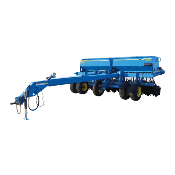
- Page 1 ‘ Model 5211 Grain Drill Operator’s Manual LANDOLL COMPANY, LLC 1900 North Street Marysville, Kansas 66508 (785) 562-5381 800-428-5655 ~ WWW.LANDOLL.COM F-725-0122...
-
Page 2: Instructions For Ordering Parts
The identification plate, which lists the model number and serial number, is located on the front of the frame. SERIAL NUMBER The serial number is located on the identification plate. The Following information will help decode the 5211 Grain Drill serial number 52H2022100 = xxmyysssss QR CODE DECAL... - Page 3 DANGER DO NOT operate or perform any maintenance tasks on this equipment until you have completed the following: 1. Receive proper training to operate this equipment safely. 2. Read and understand the operator’s manual. 3. Be thoroughly trained on inspection and repair procedures. Failure to comply with this warning may result in serious injury or possibly death.
- Page 5 Small Seed Attachment Installation (Option) ......3-4 5211 Hydraulic Marker Installation (Optional)......3-7 Operation Tractor Preparation.
- Page 6 TABLE OF CONTENTS Fertilizer – Rate Adjustment........4-15 Fertilizer –...
-
Page 7: Introduction And Safety Information
Introduction and Safety Information The Landoll Model 5211 Grain Drill is a quality product designed to give years of trouble free performance. By following each section of this manual, your system will perform as designed for you and your operation. -
Page 8: Understanding Safety State- Ments
(decals) The safety statements contained in this manual relate to attached to the machine. This section explains their the operation of the Model 5211 Grain Drill. meaning. 1. Examine safety decals and be sure you have the correct safety decals for the implement. - Page 9 TABLE OF CONTENTS Transporting Safety Maintenance Safety 1. Understand the procedure before doing the work. Use IMPORTANT proper tools and equipment. It is the responsibility of the owner/operator to 2. Make sure all moving parts have stopped. comply with all state and local laws. 3.
-
Page 10: Prepare For Emergencies
TABLE OF CONTENTS Prepare for Emergencies Safety Chain 1. Keep a First Aid Kit and Fire Extinguisher handy. 1. Use a chain with a strength rating equal to or greater than the gross weight of towed machinery, which is 2. Keep emergency numbers for doctor, ambulance, 10,100 pounds minimum in accordance with ASAE hospital, and fire department near the phone. -
Page 11: Safety Decals And Reflectors
Safety Decals and Reflectors New safety signs may be ordered from your Landoll dealer. Refer to this section for parts and proper safety The 5211 grain drill is equipped with all safety signs sign placement. installed for safe operation. To Install new safety signs: For you safety: 1. - Page 12 TABLE OF CONTENTS P/N 144193 SIS 20MPH Front of hitch, pull hitch option QTY. 1 P/N 144193 SIS 20MPH Front of frame, 3-point option QTY. 1 P/N 211045 Important: Air System Operation Front of hitch, pull hitch option QTY. 1 P/N 211045 Important: Air System Operation Front of frame, 3-point option...
- Page 13 P/N 528934 Yellow Reflector End of frame, both ends QTY. 2 P/N 528933 Red Reflector Outer ends of rear side of box, bottom QTY. 2 P/N 528933 Red Reflector Middle of rear side of box, bottom, 5211-15’ & 5211-20’ QTY. 2...
- Page 14 P/N 528938 Orange Reflector Outer ends of rear side of box, top QTY. 2 P/N 528938 Orange Reflector Middle of rear side of boxes, top, 5211-15’ & 5211-20’ QTY. 2 P/N 224589 SIS 20 mile/h Back of seed box QTY. 1...
- Page 15 TABLE OF CONTENTS P/N 224589 SIS 20 mile/h Back of small seed boxes QTY. 1 P/N 70260977 SMV EMBLEM Back of seed box QTY. 1 P/N 70260977 SMV EMBLEM Back of small seed boxes QTY. 1 P/N 141597 ELECTROCUTION HAZARD Front side of RH and LH marker mounts QTY.
- Page 16 TABLE OF CONTENTS Table provided for general use. NOTES: 1-10 F-725-0122...
-
Page 17: Specifications
Warranty Registration This manual is compiled as a guide for owners and operators of the 5211 grain drill. Read it carefully so as to be able to follow the suggestions made. Please take time Be certain to register the grain drill Online registration at to understand the proper maintenance schedule and www.landoll.com... - Page 18 1) subjected to or operated in a manner which, at any time, have exceeded the product design limits: 2) repaired or altered outside our factory in any way so as, in the judgment of Landoll Company, LLC , to affect its stability or reliability: 3) subject to misuse, negligence, accident, or has been operated in a manner expressly prohibited in the instructions;...
- Page 19 This exclusive remedy shall not be deemed to have failed of its essential purpose so long as Landoll Company, LLC is willing and able to repair or replace defective parts in the prescribed manner.
-
Page 20: Model Specifications
13,172 LBS. 5211-20X10 20” 10” 20’ - 1” 12,200 LBS. NOTE: Specifications Are Subject To Change Without Prior 5211 SERIES GRAIN DRILL W/FERTILIZER Transport Estimated Model Number Working Width Row Spacing No. of Openers Width Weight 5211-10X7.5 10 - 0”... - Page 21 TABLE OF CONTENTS 5211 SERIES GRAIN DRILL W/SMALL GRASS SEED Transport Estimated Model Number Working Width Row Spacing No. of Openers Width Weight 5211-10X7.5 10’ - 0” 7-1/2” 10’ - 0” 9,029 LBS. 5211-12-1/2X7.5 12.5’ - 0” 7-1/2” 12’ - 6”...
-
Page 22: Tire Inflation
TABLE OF CONTENTS Tire Inflation Tire Inflation Pressure (Psi) Tire Size Manufacturer Ply/Load Rating (Max.) 11L X 15 Good Year 12 Ply/3860 LBS. 52 psi LOAD INDEX 134/4680 LBS. 280/70R15 Firestone 64 psi @ 40MPH Recommended Torque Specification For Lug Bolts and Nuts Bolt Size Torque (FT. -
Page 23: General Torque Specifications (Rev. 4/97)
TABLE OF CONTENTS General Torque Specifications (rev. 4/97) TORQUE SPECIFIED IN FOOT POUNDS This chart provides tightening torques for general purpose applications when special torques are not specified on process or drawing. Assembly torques apply to plated nuts and cap-screws assembled without supplemental lubrication (as received condition). -
Page 24: Hydraulic Fitting Torque Specifications
TABLE OF CONTENTS Hydraulic Fitting Torque Specifications TORQUE IS SPECIFIED IN FOOT POUNDS- 37 JIC, ORS, & ORB (REV. 10/97) This chart provides tightening torques for general purpose applications when special torques are not specified on process or drawing. Assembly torques apply to plated nuts and capscrews assembled without supplemental lubrication (as received condition). - Page 25 TABLE OF CONTENTS 25-3/4" OPENER 19-9/16" DRIVE SMALL SEED 15-1/2" 14-1/2" MARKER DRIVE 10-5/8" WHEEL DRIVE SEED 7-1/2" Figure 2-4: 5211-10 7.5” Spacing Small Seed/Marker Placement...
- Page 26 TABLE OF CONTENTS 20-1/16" AGITATOR 24-1/2" OPENER 20-3/8" DRIVE FERTILIZER 7" 14-1/2" DRIVE DRIVE SEED WHEEL 10" Figure 2-5: 5211-10’ 7.5” Spacing Fertilizer Placement 2-10 F-725-0122...
- Page 27 TABLE OF CONTENTS 26-1/2" OPENER 20-1/8" DRIVE SMALL SEED 9-3/4" 7-1/16" DRIVE DRIVE WHEEL SEED 6" Figure 2-6: 5211-10’ 6” Spacing Placement 2-11...
- Page 28 TABLE OF CONTENTS 4-9/16" 8" DRIVE 10-3/4" 4-1/4" MARKER OPENER SMALL SEED DRIVE 6-1/2" WHEEL 8" DRIVE MARKER SEED 7-1/2" Figure 2-7: 5211-12-1/2’ 7.5” Spacing Small Seed/Marker Placement 2-12 F-725-0122...
- Page 29 TABLE OF CONTENTS 5-1/16" AGITATOR 4-1/4" 5-3/8" DRIVE 4" DRIVE 9-1/2" WHEEL DRIVE FERTILIZER OPENER SEED 10" Figure 2-8: 5211-12-1/2’ 10” Spacing Fertilizer Placement 2-13...
- Page 30 TABLE OF CONTENTS 17-13/16" GAUGE 17-13/16" DRIVE WHEEL WHEEL 16-5/8" COMPRESSOR 8" MARKER 8" MARKER 7-1/2" Figure 2-9: 5211-12-1/2’ 7-1/2” 3-Point Placement 2-14 F-725-0122...
- Page 31 TABLE OF CONTENTS 12-3/8" DRIVE SMALL SEED 25-3/4" OPENER 14-1/2" 3" DRIVE 5-1/2" DRIVE 5-1/2" WHEEL MARKER MARKER SEED 7-1/2" Figure 2-10: 5211-15’ 7.5” Spacing Small Seed/Marker Placement 2-15...
- Page 32 TABLE OF CONTENTS 12-3/8" 12-3/8" AGITATOR AGITATOR 14-1/2" DRIVE WHEEL 1" 12-7/8" DRIVE DRIVE 24-1/2" SEED FERTILIZER OPENER 10" Figure 2-11: 5211-15’ 10” Spacing Fertilizer Placement 2-16 F-725-0122...
- Page 33 TABLE OF CONTENTS 12-1/16" GAUGE WHEEL 12-1/16" 5-1/2" DRIVE MARKER WHEEL 18-1/8" 5-1/2" COMPRESSOR MARKER 7-1/2" Figure 2-12: 5211-15’ 7-1/2” 3-Point Placement 2-17...
- Page 34 TABLE OF CONTENTS 25-3/4" OPENER 16-7/8" 14-1/2" 16-7/8" DRIVE DRIVE DRIVE SMALL SEED WHEEL SMALL SEED 4-1/4" 4-1/4" 12-3/4" 12-3/4" DRIVE DRIVE MARKER MARKER SEED SEED 7-1/2" Figure 2-13: 5211-20’ 7.5” Spacing Small Seed/Marker Placement 2-18 F-725-0122...
- Page 35 TABLE OF CONTENTS 12-3/8" 12-3/8" AGITATOR AGITATOR 14-1/2" 24-1/2" DRIVE OPENER WHEEL 17-5/8" 17-5/8" 4" 4" DRIVE DRIVE DRIVE DRIVE FERTILIZER FERTILIZER SEED SEED 10" Figure 2-14: 5211-20’ 10” Spacing Fertilizer Placement 2-19...
- Page 36 TABLE OF CONTENTS 25-3/4" OPENER 12-3/4" 12-3/4" MARKER MARKER 1-11/16" 1-11/16" DRIVE DRIVE WHEEL WHEEL 1-3/8" COMPRESSOR 7-1/2" Figure 2-15: 5211-20’ 7-1/2” 3-Point Placement 2-20 F-725-0122...
- Page 37 TABLE OF CONTENTS Ø .406 34-1/4" 34-1/4" 1" 12" 7-1/2’ SEED BOX P/N 154842 2" 46" Ø .406 46" 2" 1" 12" 10’ SEED BOX P/N 143932 2" 61" Ø .406 61" 2" 1" 12" 12-1/2’ SEED BOX P/N 159102 Figure 2-16: Small Seed Attachment Drilling Placement 2-21...
- Page 38 TABLE OF CONTENTS Table provided for general use. NOTES: 2-22 F-725-0122...
-
Page 39: Assembly Safety
Assembly Instructions Assembly Safety WARNING Your new 5211 Grain Drill comes nearly completely Do not attempt to lift heavy parts (such as the assembled from the factory and ready to go to the field. frame, wheel lift, and pull hitch) manually. Use a... - Page 40 TABLE OF CONTENTS Rebounder Assembly DANGER DANGER 1. Attach rebounder mount bracket with 1/2 x 1-1/4 Opener blades are extremely sharp. Exercise round head screw and 1/2 flange nut See Figure 3-1. extreme care when working on or near opener 2.
- Page 41 TABLE OF CONTENTS Press Wheel Assembly DANGER DANGER 1. Attach each press wheel assembly to each air opener Opener blades are extremely sharp. Exercise assembly on the Grain Drill using press wheel arm pin extreme care when working on or near opener and 3/4 lock nut See Figure 3-2.
- Page 42 Use these instructions to install the optional small seed rear of the main seed box. Install the 2-hole mounting attachment to the rear main seed box of the 5211 Grain plates and 3/8” hex lock nuts on the inside of the main Drill.
- Page 43 EXISTING MAIN SEED BOX ASSEMBLY 3/8-16 LOCKNUT EXISTING SMV SIGN SMALL SEED BOX ASSEMBLY RELOCATED SMV SIGN, SIS SIGN 5211-10’-12-1/2’ 2 HOLE SMV BRACKET, SEED SHAFT SHIELD, MOUNTING PLATE 1/4 X 1-1/4 HEX BOLTS, HEX LOCK NUTS DRIVE TUBE, SQUARE...
- Page 44 TABLE OF CONTENTS 9. Attach the front of the chain adjustment bracket to the 14. Remove the rear safety shield from the seed shaft seed box bracket with the 1/2-13 x 1-1/4 hex head cap bearing assembly. Loosen the rear mounting screws, screw.
- Page 45 5211 Hydraulic Marker Installa- WARNING tion (Optional) Escaping hydraulic fluid can cause serious The 5211 grain drill may be equipped with optional personnel injury. Relieve system pressure before hydraulic markers. repairing, adjusting, or disconnecting. Wear proper hand and eye protection when searching CAUTION for leaks.
- Page 46 TABLE OF CONTENTS B1 ports on the front of the marker sequence valve. 17. Install the “Danger – Electrocution” decals to the front of the marker mounts next to the yellow reflectors. 8. Install the male couplers on the front of the marker hoses.
-
Page 47: Operation
DANGER DANGER DANGER DANGER Never allow anyone to ride on the 5211 Grain Drill When transporting the unit, place cylinder at any time. Allowing a person to ride on the lockouts in the transport lock position after fully machine can inflict serious personal injury or extending the cylinders. -
Page 48: Tractor Preparation
TABLE OF CONTENTS Tractor Preparation The Landoll 5211 Grain Drill is designed to be pulled by tractor equipped with a double lip or clevis type hitch. If your tractor is not equipped as such, you need to purchase the hitch from your local tractor dealer. - Page 49 TABLE OF CONTENTS Transport Locks - Pull Hitch b.Remove the L-pins and hairpin clips from the stored transport locks. 1. Transport lock pins are provided to secure the Grain c.Slide the transport locks over the extended cylinder Drill in raised position. Do not depend on hydraulics shafts.
- Page 50 TABLE OF CONTENTS Leveling the Hitch Clevis CAUTION 1. The hitch clevis height should be adjusted to match Excessive speed may result in loss of control of the drawbar height of the tractor. This will allow the the tractor and implement, reduced braking, or hitch to operate through its most efficient range and failure of the implement tires or structure.
- Page 51 TABLE OF CONTENTS 6. A safety chain is provided with the implement to e.Plug in the safety lights to the tractor seven-pin insure safe transport. connector. a.The safety chain should have a tensile strength f.Fully raise the Grain Drill lift, hitch, and openers. equal to or greater than the gross weight of the g.Make sure all transport locks and pins are installed.
- Page 52 TABLE OF CONTENTS Compressor Operation - Air 3. System pressure should not exceed 100 psi. This is the maximum recommended working pressure the air Opener springs are rated for. This will provide maximum down pressure for the row units. A system relief valve is 1.
- Page 53 Loup Drill Monitor Operation The Grain Drill is equipped with a hydraulic lift system to 1. The 5211 Grain Drill can be equipped with a Loup raise and lower the unit from transport to planting Mini drill monitor. The drill monitor will monitor position.
- Page 54 TABLE OF CONTENTS Seed Meter Gate Adjustment 2. The second seed gate position is for peas, small soybeans, etc. If excess cracking occurs, move the The seed meter has an adjustable seed gate to handle to the third position. accommodate various seed sizes for planting. The seed 3.
-
Page 55: Seed Rate Adjustment
TABLE OF CONTENTS Seed Rate Adjustment c.Using a ratchet wrench extension, and 3/4” socket, insert the socket through the hole in the end box The seeding rate is adjusted for each section with the support to the hex-head adjustment bushing. Turn the threaded seed rate adjustment at left end of drill, the hex-head adjustment bushing in or out, until the 20’... - Page 56 TABLE OF CONTENTS Meter/Seed Rate Handle 6. With all lock collars secure on the seed shaft and all slack removed from between the spacers, verify that Adjustment each meter is actually zeroed out. The feed roll should not be protruding or recessed inside any of the 1.
- Page 57 TABLE OF CONTENTS SEED RATE = (AVG SEED WEIGHT) X 65896 (NO. OF ROTATIONS) X (ROW SPACING) EXAMPLE = (.1707 LBS.) X 65896 =75 LBS./ACRE (20 ROTATIONS) X (7.5”) # SEEDS per ROW = (SEED RATE) X (SEEDS/LB) X (NO. OF ROTATIONS) X (ROW SPACING) 65896 EXAMPLE = (60 LBS./ACRE) X (2500 SEEDS/LBS.) X (20 ROTATIONS) X (7.5”) =341 SEEDS PER ROW...
-
Page 58: Seed Rate Calibration
TABLE OF CONTENTS Seed Rate Calibration Dry Fertilizer Combination Box 1. The seed rate charts are in pounds per acre and 1. If the Grain Drill is equipped with the dry fertilizer based on an average seed size See Figure 4-11. - Page 59 TABLE OF CONTENTS 3. When using both seed and dry fertilizer, fill the seed 5. When both compartments are being used for seed, box keeping fill shield in closed position over fertilizer open seed box lids and lift and rotate the fill shield See Figure 4-14.
-
Page 60: Fertilizer Box - Clean Out
TABLE OF CONTENTS Fertilizer Box – Clean Out latches and allow the door to swing forward. 3. Dry fertilizer is very corrosive and absorbs moisture. 1. The fertilizer meters accessed Clean out any fertilizer as soon as possible after using maintenance or cleaning by removing the door the drill. - Page 61 TABLE OF CONTENTS Figure 4-18: Fertilizer Box Chart Fertilizer – Rate Adjustment 2. The fertilizer chart is based upon average size dry fertilizer with a density of 65 lbs per cubic foot. If using 1. The dry fertilizer rate is adjusted by changing sprocket a fertilizer with a different density, apply the following ratios for each section.
- Page 62 TABLE OF CONTENTS Fertilizer – Rate Calibration Small Seed Rate Adjustment 1. Dry fertilizer can be affected by type, density, size, WARNING humidity, and field conditions. Operator should verify actual fertilizer rate output before planting. • To prevent damage to the seed meters, do not 2.
- Page 63 TABLE OF CONTENTS d.Turn the large seed rate adjusting nut on the left NOTE side of the seed shaft bearing in or out to the desired Seeding rates are based on clean untreated average size setting. The desired letter on the seed rate adjusting seed.
- Page 64 TABLE OF CONTENTS Seed Rate Calibration 3. To check the seeding rate: a.Select three seed meters next to each other, and 1. The seed rate charts are in pounds per acre and disconnect the rubber seed tubes to be able to catch based on an average seed size See Figure 4-20.
- Page 65 TABLE OF CONTENTS Small Seed Meter Assembly/Adjustment 1. If the small seed meter shaft assembly is disassembled for maintenance or repair, the seed meters and seed rate adjustment will need to be reset or zeroed to set the meters equally across the seed box.
- Page 66 TABLE OF CONTENTS Air Spring Adjustment 2. To adjust the air spring location, first relieve the system air pressure. Loosen, but do not remove the 1. The air pressure delivered to the air springs is the 3/4-16 hex jam nut at the top of the air spring and the same for all openers.
- Page 67 TABLE OF CONTENTS Opener Blade Adjustment See Figure 4-23. When removing shim(s) from between the blade and the casting, move them to the 1. To insure peak performance of the opener assembly outside of the blade and place under the dust cap. and maximum bearing life a proper opener blade This will keep track of the shims and not change the pinch point should be maintained.
- Page 68 TABLE OF CONTENTS Opener Scraper Adjustment 2. To adjust the scraper blade, loosen the 1/2-13 hex flange spiralock nut holding the blade, and slide the 1. The opener is equipped with a scraper to keep the blade up or down to achieve the desired clearance inside surfaces of the opener blades clean.
- Page 69 TABLE OF CONTENTS Opener Soil Strip Adjustment 3. The metal backing strip should be centered over the soil strip. Do not allow the metal backing strip to rub 1. The soil strip runs along the side of the opener blade against the opener blade or it will tend to trap residue.
- Page 70 TABLE OF CONTENTS Spring Opener LIGHT SETTING UPPER HOLE 1. The 5211 may be equipped with a spring opener. This CROSS-BOLT opener has two 15.8” (400mm) x .138” (3.5mm) HEAVY SETTING opener blades, rigid scraper, adjustable LOWER HOLE non-swivel press wheel. The opener has 10” of vertical travel.
- Page 71 TABLE OF CONTENTS Walkboard 2. The walkboard may be raised to allow easier service access to the openers. To raise the walkboard, lift at 1. The walkboard on the Grain Drill provides a stable the center rear of the wallboard and rotate forward. A platform to work from while filling the seed box latch is provided to hold the walkboard in the raised Figure...
- Page 72 TABLE OF CONTENTS Ladder Use and Transport Requirements WALKBOARD 1. When transporting the 5211 Grain Drill: a.The ladder should be in the raised position (laying across the top of the walkboard) and secured with the See Figure 4-29. LADDER b.The ladder should also be in the raised position when working in the field to prevent damage when working near trees, fences, power lines, etc.
- Page 73 TABLE OF CONTENTS Hydraulic Row Markers (Option) 3. With both markers in the raised position, slowly engage the marker hydraulics. One marker will 1. The Grain Drill may be equipped with optional extend. Reversing the hydraulic lever will raise that hydraulic row markers.
- Page 74 TABLE OF CONTENTS Hydraulic Row Marker Disc 2. The disc blade may also be configured to push or pull soil towards the drill. Adjustment (Option) a.To change the direction of the disc blade, first remove the 4 bolts and dust cap retainer from each CAUTION hub assembly.
- Page 75 TABLE OF CONTENTS Coulter Hitch (Option) operate the coulter hydraulics. 3. The amount of down pressure needed to operate the 1. The Grain Drill may be equipped with an optional coulters will vary with soil conditions, moisture and coulter hitch See Figure 4-32.
- Page 76 1. The 5211 may be equipped with a 3 point hitch versus each drive wheel. Measure the pin-to-pin length of a pull hitch See Figure 4-33. The 3 point hitch is a...
-
Page 77: Maintenance And Lubrication
TABLE OF CONTENTS Chapter 5 Maintenance and Lubrication Wheel Bearing Maintenance – 9. Tighten the slotted nut while rotating the hub until there is a slight resistance to wheel rotation. Then, Triple-Lip back the slotted nut off one notch, until the wheel rotates freely without end play. -
Page 78: Hydraulic Maintenance
WARNING replace all seals. Seal kits are available from your Landoll dealer. The Grain Drill has negative tongue weight. Use a 3. Check all hydraulic hoses weekly. Look for binding or properly sized locking style hitch pin for the cracking. - Page 79 TABLE OF CONTENTS PARKING STAND PARKING POSITION Figure 5-4: Parking Stand Parking Position d.Lower the Grain Drill to the ground. JACK PARKING e.Remove the jack from the storage position POSITION Figure 5-5 and install the jack in the storage position See Figure 5-6.
-
Page 80: Lubrication Maintenance
Table 5-1 specifies the lubrication points and intervals Drill, SAE multi-purpose EP grease, or EP grease on the 5211 Grain Drill. Proper maintenance of your with 3-5% molybdenum sulfide is recommended. machine will, under normal operating conditions, help Wipe soil from fittings before greasing. Replace any to keep it operating at or near its peak performance lost or broken fittings immediately. - Page 81 TABLE OF CONTENTS DETAIL A DETAIL A Figure 5-7: Lubrication Points...
- Page 82 TABLE OF CONTENTS Storage 5. Check opener pinch point for proper adjustment. 6. Clean and repack the wheel bearings. Preparing the Grain Drill for storage during extended 7. Inspect all nuts and bolts for tightness. periods of time will not only help protect the drill, but 8.
-
Page 83: Troubleshooting Guide
Troubleshooting Guide The Troubleshooting Guide, shown below, is included to help you quickly locate problems that can happen using your 5211 Grain Drill. Follow all safety precautions stated in the previous sections when making any adjustments to your machine. PROBLEM... - Page 84 TABLE OF CONTENTS PROBLEM PROBABLE CAUSE SOLUTION UNEVEN SEED SPACING Excessive field speed Reduce field speed. Unclean seed Use clean seed Build up of seed treatment in seed cup Clean out seed meters Seed tubes sagging Replace seed tube Drive type (sprocket ratio) too slow Use faster drive type and readjust seed meter opening.
- Page 85 Document Control Revision Log: Date Form # Improvement(s): Description and Comments 10/04/2013 F-725-0713 Initial Release 01/10/2022 F-725-0122 Updated whole manual, added rebounder, spring openers...
- Page 86 Equipment from Landoll Company, LLC is built to exacting standards ensured by ISO 9001 registration at all Landoll manufacturing facilities. Model 5211 Grain Drill Operator’s Manual Re-order Part Number F-725 LANDOLL COMPANY, LLC 1900 North Street Marysville, Kansas 66508 (785) 562-5381 800-428-5655 ~ WWW.LANDOLL.COM...
Need help?
Do you have a question about the 5211 and is the answer not in the manual?
Questions and answers