
Related Manuals for Landoll 5531 Series


Summary of Contents for Landoll 5531 Series
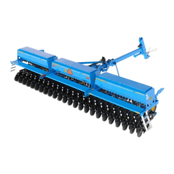
- Page 1 ‘ Model 5531 Grain Drill Operator’s Manual LANDOLL COMPANY, LLC 1900 North Street Marysville, Kansas 66508 (785) 562-5381 800-428-5655 ~ WWW.LANDOLL.COM F-716-2403...
-
Page 2: Instructions For Ordering Parts
Instructions for Ordering Parts ** Repair parts must be ordered through an Authorized Dealer ** DEALER INSTRUCTIONS FOR ORDERING PARTS FROM LANDOLL PARTS DISTRIBUTION CENTER Phone #: 800-423-4320 785-562-5381 Fax #: 888-527-3909 Order online: dealer.landoll.com IDENTIFICATION PLATE The identification plate, which lists the model number and serial number, is located on the front of the frame. - Page 3 DANGER DO NOT operate or perform any maintenance tasks on this equipment until you have completed the following: 1. Receive proper training to operate this equipment safely. 2. Read and understand the operator’s manual. 3. Be thoroughly trained on inspection and repair procedures. Failure to comply with this warning may result in serious injury or possibly death.
- Page 5 Table of Contents Introduction and Safety Information Understanding Safety Statements ........1-2 Transporting Safety .
- Page 6 Maintenance ..........4-11 Openers –...
-
Page 7: Introduction And Safety Information
Introduction and Safety Information The Landoll Model 5531 Grain Drill is a quality product designed to give years of trouble free performance. By following each section of this manual, your system will perform as designed for you and your operation. -
Page 8: Understanding Safety Statements
TABLE OF CONTENTS Understanding Safety NOTE Statements Make sure you read and understand the information contained in this manual and on the machine signs (decals) before you attempt to operate or maintain this You will find various types of safety information on the machine. - Page 9 TABLE OF CONTENTS Transporting Safety Maintenance Safety 1. Understand the procedure before doing the work. Use IMPORTANT proper tools and equipment. It is the responsibility of the owner/operator to 2. Make sure all moving parts have stopped. comply with all state and local laws. 3.
-
Page 10: Prepare For Emergencies
TABLE OF CONTENTS Prepare for Emergencies Safety Chain 1. Keep a First Aid Kit and Fire Extinguisher handy. 1. Use a chain with a strength rating equal to or greater than the gross weight of towed machinery, which is 2. Keep emergency numbers for doctor, ambulance, 10,100 pounds minimum in accordance with ASAE hospital, and fire department near the phone. -
Page 11: Safety Decals And Reflectors
TABLE OF CONTENTS Safety Decals and Reflectors New safety signs may be ordered from your Landoll dealer. Refer to this section for parts and proper safety The 5531 grain drill is equipped with all safety signs sign placement. installed for safe operation. - Page 12 TABLE OF CONTENTS P/N 224512 Important: Air System Front, left side of hitch, bottom QTY. 1 P/N 224512 Important: Air System Inside lid, center box QTY. 1 P/N 211045 Important: Air System Operation Front, left side of hitch, 2nd from bottom QTY.
- Page 13 TABLE OF CONTENTS P/N 211082 Important: Opener Air Pressure Cover, air opener valve assembly QTY. 1 P/N 528934 Yellow Reflector End of center box frame, both ends QTY. 2 P/N 528934 Yellow Reflector Outer ends of wing walkboards QTY. 4 P/N 528933 Red Reflector Light brackets, wings...
-
Page 14: Orange Reflector
TABLE OF CONTENTS P/N 528933 Red Reflector Back, lower of center box frame, both ends QTY. 2 P/N 528938 Orange Reflector Light brackets, wings QTY. 2 P/N 528938 Orange Reflector Back, lower of center box frame, both ends QTY. 2 P/N 224589 SIS 20 mile/h (Center Seed Box) Back of center seed box... -
Page 15: Smv Emblem
TABLE OF CONTENTS P/N 224589 SIS 20 mile/h (Center SmallSeed Box) Back of center small seed boxes QTY. 1 70260977 SMV Emblem Back of center seed box QTY. 1 P/N 70260977 SMV Emblem Back of center small seed boxes QTY. 1 P/N 141597 Danger: Electrocution Hazard Front side of RH and LH marker mounts... - Page 16 TABLE OF CONTENTS Table provided for general use. NOTES: 1-10 F-716-2403...
-
Page 17: Specifications
10 days of purchase or lease, in operators of the 5531 grain drill. Read it carefully so as to order to be on file at Landoll and eligible for Warranty. be able to follow the suggestions made. Please take time... - Page 18 1) subjected to or operated in a manner which, at any time, have exceeded the product design limits: 2) repaired or altered outside our factory in any way so as, in the judgment of Landoll Company, LLC , to affect its stability or reliability: 3) subject to misuse, negligence, accident, or has been operated in a manner expressly prohibited in the instructions;...
-
Page 19: User's Obligation
This exclusive remedy shall not be deemed to have failed of its essential purpose so long as Landoll Company, LLC is willing and able to repair or replace defective parts in the prescribed manner. -
Page 20: Model Specifications
14’ - 6” 25,547 LBS. 6 Bolt (Wing) 5531-40X10 40’ - 0” 10” 14’ - 6” 23,540 LBS. NOTE: Specifications Are Subject To Change Without Prior 5531 SERIES GRAIN DRILL W/SMALL GRASS SEED Model Working No. of Transport Estimated Number Width Spacing... -
Page 21: Tire Inflation
TABLE OF CONTENTS 5531 SERIES GRAIN DRILL CAPACITIES Seed Box Small Seed Box Model Capacity Seed/Fertilizer Capacity Seed Box Fertilizer Box Capacity Capacity 5531-30’ 97.5 Bushels 60 Bushels 3150 LBS. 10.8 Bushels 5531-40’ 130 Bushels 80 Bushels 4200 LBS. 14.1 Bushels... -
Page 22: General Torque Specifications (Rev. 4/97)
TABLE OF CONTENTS General Torque Specifications (rev. 4/97) TORQUE SPECIFIED IN FOOT POUNDS This chart provides tightening torques for general purpose applications when special torques are not specified on process or drawing. Assembly torques apply to plated nuts and cap-screws assembled without supplemental lubrication (as received condition). -
Page 23: Hydraulic Fitting Torque Specifications
TABLE OF CONTENTS Hydraulic Fitting Torque Specifications TORQUE IS SPECIFIED IN FOOT POUNDS- 37 JIC, ORS, & ORB (REV. 10/97) This chart provides tightening torques for general purpose applications when special torques are not specified on process or drawing. Assembly torques apply to plated nuts and capscrews assembled without supplemental lubrication (as received condition). - Page 24 TABLE OF CONTENTS Figure 2-4: 5531-30 Left Wing Placement F-716-2403...
- Page 25 TABLE OF CONTENTS Figure 2-5: 5531-30 Center Placement...
- Page 26 TABLE OF CONTENTS Figure 2-6: 5531-30 Right Wing Placement 2-10 F-716-2403...
- Page 27 TABLE OF CONTENTS Figure 2-7: 5531-40 Left Wing Placement 2-11...
- Page 28 TABLE OF CONTENTS Figure 2-8: 5531-40 Center Placement 2-12 F-716-2403...
- Page 29 TABLE OF CONTENTS Figure 2-9: 5531-40 Right Wing Placement 2-13...
- Page 30 TABLE OF CONTENTS Figure 2-10: 5531-30 Point Row Clutch Placement 2-14 F-716-2403...
- Page 31 TABLE OF CONTENTS Figure 2-11: 5531-40 Point Row Clutch Placement 2-15...
- Page 32 TABLE OF CONTENTS Figure 2-12: Small Seed Attachment Drilling Placement 2-16 F-716-2403...
-
Page 33: Assembly Safety
Chapter 3 TABLE OF CONTENTS Assembly Instructions Assembly Safety WARNING Your new 5531 Grain Drill comes nearly completely Do not attempt to lift heavy parts (such as the assembled from the factory and ready to go to the field. frame, wheel lift, and pull hitch) manually. Use a This section includes press wheel and option assembly hoist or a forklift to move these parts into procedures. - Page 34 TABLE OF CONTENTS Press Wheel Assembly DANGER DANGER 1. Attach each press wheel assembly to each air opener Opener blades are extremely sharp. Exercise assembly on the Grain Drill using press wheel arm pin extreme care when working on or near opener and 3/4 lock nut See Figure 3-1.
- Page 35 TABLE OF CONTENTS Table provided for general use. NOTES:...
- Page 36 TABLE OF CONTENTS Small Seed Attachment 4. Remove the 3/8” hex lock nuts and 2-hole mounting plates from the front of the small seed box assembly Installation (Option) See Figure 3-4. 5. Carefully raise the small seed attachment and insert See Figures 3-4 for small seed attachment overview.
- Page 37 TABLE OF CONTENTS EXISTING MAIN SEED BOX ASSEMBLY 3/8-16 LOCKNUT EXISTING SMV SIGN SMALL SEED BOX ASSEMBLY RELOCATED SMV SIGN, SIS SIGN 5531-30’ 2 HOLE SMV BRACKET, SEED SHAFT SHIELD, MOUNTING PLATE 1/4 X 1-1/4 HEX BOLTS, HEX LOCK NUTS DRIVE TUBE, SQUARE SMV MOUNTING BRACKET, SEED SHAFT, THREADED...
- Page 38 TABLE OF CONTENTS 9. Attach the front of the chain adjustment bracket to the 12. Remove existing 7/8 hex drive shaft above the drill 7 seed box bracket with the 1/2-13 x 1-1/4 hex head cap x 7 frame tube. Install the grass seed bracket and screw.
- Page 39 TABLE OF CONTENTS Table provided for general use. NOTES:...
- Page 40 TABLE OF CONTENTS Agitator Assembly (Option) using u-bolts and 5/8 nuts. Attach the brackets 3-1/2” from the seed box support as shown, See Figure 3-6 for locations 5531-30’-40’. Install the right & left grass seed brackets 158309 & 158310 to the rear of the main drill frame 7 x 7 tube GRASS SEED GRASS SEED BRACKET RH...
- Page 41 TABLE OF CONTENTS Replace the 144127 seed box bracket, with the 9. Install a 1” long square-holed sleeve in each bearing. 168902 agitator bracket on the outer ends of the 10. Insert the agitator square shaft through the outer seed seed boxes See Figure 3-9.
- Page 42 TABLE OF CONTENTS AGITATOR SEED AGITATOR, SQUARE SHAFT 1/4 X 1-3/4 HEX SCREW 5/16 FLANGE HEAD SHAFT BEARING BRACKET, SERRATED NUT BEARING MOUNT W/BEARING, LOCK COLLAR, 5/16 X 3/8 LONG SET SCREW 5/16 X 3/4 FLANGE SCREWS 1/4 X 1-1/2 SLOTTED SPRING PIN BEARING MOUNT 1/2 FLANGE HEAD SERRATED NUT 1/2 FLANGE...
-
Page 43: Drive Wheel
TABLE OF CONTENTS 16. Route the drive chain around the agitator shaft and in-line. to the front hex drive shaft as shown 17. Verify that the agitator sprockets and chain is in-line. . Adjust the chain tension with the front Figure 3-11 Rotate the drive wheel to verify that the drive chains idler sprocket. - Page 44 TABLE OF CONTENTS 5531 Hydraulic Marker WARNING Installation (Optional) Escaping hydraulic fluid can cause serious The 5531 grain drill may be equipped with optional personnel injury. Relieve system pressure before hydraulic markers. repairing, adjusting, or disconnecting. Wear proper hand and eye protection when searching CAUTION for leaks.
- Page 45 TABLE OF CONTENTS lock hook & latch mounts using 1-1/4 x 8-1/2 bolts, NOTE u-bolts and lock nuts. Reinstall the wing lock hook and It may be necessary to loosen the fittings and latch and clamp bushings when installing the marker bulkhead fittings and shield on the opposite side of mounts.
- Page 46 TABLE OF CONTENTS 22. Install the extension tube in the outer arm with the 30. Install a 90-degree adapter in the rod end of each holes to the outer end and pointing upward. Secure marker cylinder See Figure 3-18. the outer arm with a u-bolt and lock nuts. 31.
- Page 47 TABLE OF CONTENTS HOSE CLAMP, 3/8 X 1-3/4 BOLT, 3/8 FLAT WASHER, DETAIL A 5/8 LOCK NUTS REAR VIEW 1-1/4 X 8-1/2 BOLTS, 1-1/4 LOCK NUTS DETAIL A RH & LH MARKER MOUNT FIRST ARM RUBBER BRACE WELDMENT, CUSHION, GREASE ZERKS, 5/16 X 1 RDHD SQNK BOLTS, 50 HOUR DECALS 5/8 LOCK NUTSt...
- Page 48 TABLE OF CONTENTS 5531-30’ 5531-40’ MARKER MARKER ASSEMBLY ASSEMBLY 5/8 X 3-1/2 BOLT, 5/8 LOCK NUT HUB ASSEMBLY, ROW MARKER RUBBER SPACER, 1/2 X 3-1/2 RD HEAD SQ LINKAGE WELDMENT 3/8 X 1-1/2 SCREWS, NECK SCREWS, 3/8 FLAT WASHERS 5/8 X 1-7/8 TUBE, 1/2 FLAT WASHERS, 3/8 X 2-1/2 BOLT, 1/2 X 2-1/8 X 3-1/4...
- Page 49 TABLE OF CONTENTS C1 TO BASE 90° #8 O-RING END RIGHT #8JIC-#8 ORB STR ADAPTER LONG ADAPTER CYLINDER C2 TO BASE #8 90° FLARE 3/8” X 255” (5531-30’) SWIVEL END LEFT 3/8” X 312” (5531-40’) ADAPTER CYLINDER HOSE REAR PORTS R1 TO ROD MARKER END RIGHT...
- Page 50 TABLE OF CONTENTS Table provided for general use. NOTES: 3-18 F-716-2403...
-
Page 51: Operation
Chapter 4 TABLE OF CONTENTS Operation DANGER DANGER DANGER DANGER Never allow anyone to ride on the 5531 Grain Drill Install hitch cylinder and wring lock pins before at any time. Allowing a person to ride on the transporting. Failure to lockout the cylinders can machine can inflict serious personal injury or cause the unit to settle during transport which death to that person. -
Page 52: Initial Checklist
TABLE OF CONTENTS 5531 Operation Checklist This section is a checklist for general operating procedures. Refer to individual sections for further details on safety, settings, and proper procedures. Initial Checklist 1.Read and understand the operating manual and all Safety Information. 2.Attach the grain drill to the tractor with proper pin and safety chain. -
Page 53: Field Operation
TABLE OF CONTENTS Field Operation Never allow anyone to ride on the grain drill, stay clear of moving parts. Raise the drill when turning. Avoid backing up to prevent plugging and equipment damage. Stay away from power lines during operation when folding or unfolding the drill and markers. Electrocution can occur without direct contact. -
Page 54: Tractor Preparation
TABLE OF CONTENTS Tractor Preparation The Landoll 5531 Grain Drill is designed to be pulled by tractor equipped with a double lip or clevis type hitch. If your tractor is not equipped as such, you need to purchase the hitch from your local tractor dealer. - Page 55 TABLE OF CONTENTS Hitch Cylinder and Wing Locks 2. To install the telescoping hitch cylinder pin lock, fully raise the main lift and hitch. Remove the pin from the 1. Cylinder lock pins are provided to secure the Grain storage position and install through the hole in the Drill in raised and folded positions.
- Page 56 TABLE OF CONTENTS Folding/Unfolding the Grain Drill NOTE If the hitch is raised past the center position, fully lower The Grain Drill is equipped with hydraulic cylinders to fold the hitch, and re-raise the front of the hitch. This will and unfold the drill from transport to field position.
- Page 57 TABLE OF CONTENTS Leveling the Hitch Transporting the Grain Drill 1. When unfolding the Grain Drill the hitch is lowered to 1. Check and follow all federal, state, and local its lowest point to allow the wing fold locks to unhook requirements before transporting the Grain Drill.
-
Page 58: Safety Chain
TABLE OF CONTENTS 6. A safety chain is provided with the implement to d.Attach safety chain. insure safe transport. e.Plug in the safety lights to the tractor seven-pin a.The safety chain should have a tensile strength connector. equal to or greater than the gross weight of the f.Fully raise the Grain Drill lift, hitch, and openers. -
Page 59: Compressor Operation
TABLE OF CONTENTS The drill compressor will operate much like a regular Compressor Operation air compressor. Plug the seven-pin connector into the tractor and turn the compressor switch on. The The 5531 drill is equipped with a heavy-duty electric compressor will charge the entire system and fill the air compressor to charge and adjust See Figure 4-7... - Page 60 TABLE OF CONTENTS down pressure for the row units. A system relief Opener Air Pressure valve is installed at the front of the See Figure 4-9 Air to the openers is supplied by the drill air hitch to protect the system from excessive pressure. compressor .
-
Page 61: Maintenance
TABLE OF CONTENTS 7. To decrease opener air pressure – raise the NOTE openers out of the ground. With the tractor engine This procedure is for a normal operating air system. running, turn on the air compressor. Open the If any air leaks have developed in the drill section(s), regulator cover and turn the outer dial of the regulator they should be repaired immediately to insure equal to the desired lower pressure setting. - Page 62 TABLE OF CONTENTS Active Hydraulics - Drill Openers 3. Tractor hydraulic pressure must be balanced against opener air pressure. It will perform best to 1. Optional Active Hydraulics have been added to the set the opener air pressure first for the best planting 5531 grain drill to give the drill openers more vertical conditions, hydraulic...
- Page 63 TABLE OF CONTENTS 5. Ideally the openers will operate in the middle of the OPENER travel with the top of the opener frame level. Check GUIDE DOWN HILL this by looking at the stop tab in the slot on the side of the opener See Figure 4-12.
-
Page 64: Hydraulic Lift System
TABLE OF CONTENTS 11. A control box is located in the cab with the operator. WARNING The control box has four switches, a master control switch and a switch one for each section. Escaping hydraulic fluid can cause serious •The master switch when activated will turn off all sec- personnel injury. - Page 65 TABLE OF CONTENTS Loup Drill Monitor Operation 5. Pulses are preset for the drill monitor. Initially the pulses are set at 68. The pulse setting may vary 1. The 5531 Grain Drill can be equipped with a Loup depending on the conditions the drill is planting in. Mini or Elite drill monitor.
- Page 66 TABLE OF CONTENTS Seed Meter Gate 2. The second seed gate position is for peas, small soybeans, etc. If excess cracking occurs, move the Adjustment handle to the third position. 3. Use the third seed gate position for large peas, large The seed meter has an adjustable seed gate to soybeans, etc.
-
Page 67: Seed Rate Adjustment
TABLE OF CONTENTS Seed Rate Adjustment b.Loosen the locking nut on the square seed shaft with the adjustment wrench See Figure 4-19. 1. Wrenches are provided to adjust the seed rate. They c.Using the seed rate adjustment wrench, insert the are stored on outside end of LH seed box socket through the hole in the end box support to the Figure 4-18... - Page 68 TABLE OF CONTENTS Meter/Seed Rate Handle 6. With all lock collars secure on the seed shaft and all slack removed from between the spacers, verify that Adjustment each meter is actually zeroed out. The feed roll should not be protruding or recessed inside any of the 1.
- Page 69 TABLE OF CONTENTS SEED RATE = (AVG SEED WEIGHT) X 65896 (NO. OF ROTATIONS) X (ROW SPACING) EXAMPLE = (.1707 LBS.) X 65896 =75 LBS./ACRE (20 ROTATIONS) X (7.5”) # SEEDS per ROW = (SEED RATE) X (SEEDS/LB) X (NO. OF ROTATIONS) X (ROW SPACING) 65896 EXAMPLE = (60 LBS./ACRE) X (2500 SEEDS/LBS.) X (20 ROTATIONS) X (7.5”) =341 SEEDS PER ROW...
-
Page 70: Seed Rate Calibration
TABLE OF CONTENTS Seed Rate Calibration Dry Fertilizer Combination Box 1. The seed rate charts are in pounds per acre and 1. If the Grain Drill is equipped with the dry fertilizer based on an average seed size See Figure 4-21. - Page 71 TABLE OF CONTENTS 3. When using both seed and dry fertilizer, fill the seed 5. When both compartments are being used for seed, box keeping fill shield in closed position over fertilizer open seed box lids and lift and rotate the fill shield See Figure 4-24.
-
Page 72: Fertilizer Box - Clean Out
TABLE OF CONTENTS Fertilizer Box – Clean Out latches and allow the door to swing forward. 3. Dry fertilizer is very corrosive and absorbs moisture. 1. The fertilizer meters accessed Clean out any fertilizer as soon as possible after using maintenance or cleaning by removing the door the drill. - Page 73 TABLE OF CONTENTS Figure 4-28: Fertilizer Box Chart Fertilizer – Rate Adjustment 2. The fertilizer chart is based upon average size dry fertilizer with a density of 65 lbs per cubic foot. If using 1. The dry fertilizer rate is adjusted by changing sprocket a fertilizer with a different density, apply the following ratios for each section.
- Page 74 TABLE OF CONTENTS Fertilizer – Rate Calibration Small Seed Rate Adjustment 1. Dry fertilizer can be affected by type, density, size, WARNING humidity, and field conditions. Operator should verify actual fertilizer rate output before planting. • To prevent damage to the seed meters, do not 2.
- Page 75 TABLE OF CONTENTS d.Loosen the 1” locking nut with the seed rate f.Re-tighten the 1' locking nut with the seed rate adjusting wrench Figure 4-29 adjusting wrench against the bearing. Figure 4-30. e.Turn the large seed rate adjusting nut with the NOTE adjustment wrench of the seed shaft bearing in or out Seeding rates are based on clean untreated average size...
- Page 76 TABLE OF CONTENTS Seed Rate Calibration b.Fill the box with a sufficient amount of seed over the three meters. 1. The seed rate charts are in pounds per acre and c.Lower the openers to planting position to engage based on an average seed size 7-1/2” spacing the seed clutch.
- Page 77 TABLE OF CONTENTS Small Seed Meter Assembly/Adjustment 1. If the small seed meter shaft assembly is disassembled for maintenance or repair, the seed meters and seed rate adjustment will need to be reset or zeroed to set the meters equally across the seed box.
- Page 78 TABLE OF CONTENTS Air Spring Adjustment 2. To adjust the air spring location, first relieve the system air pressure. Loosen, but do not remove the 1. The air pressure delivered to the air springs is the 3/4-16 hex jam nut at the top of the air spring and the same for all openers.
- Page 79 TABLE OF CONTENTS Opener Blade Adjustment Example 3 & 3, or 3 & 2. 1. To insure peak performance of the opener assembly Opener blades must turn freely and not bind. and maximum bearing life a proper opener blade pinch point should be maintained. The pinch point of Opener blades must maintain contact at pinch point the blades is the lower front point where the right and while rotating.
- Page 80 TABLE OF CONTENTS Opener – Press Wheel Opener Scraper Adjustment Adjustment 1. The opener is equipped with a scraper to keep the inside surfaces of the opener blades clean. In dryer 1. The seeding depth of each individual opener is conditions, the scraper can be adjusted farther away controlled by the press wheel depth adjustment from the opener blades for greater clearance.
- Page 81 TABLE OF CONTENTS 2. To adjust the scraper blade, loosen the 1/2-13 hex 3. A properly maintained opener blade pinch point will flange spiralock nut holding the blade, and slide the reduce the amount of soil that enters between the blade up or down to achieve the desired clearance opener blades.
- Page 82 TABLE OF CONTENTS Opener Soil Strip Adjustment 3. The metal backing strip should be centered over the soil strip. Do not allow the metal backing strip to rub 1. The soil strip runs along the side of the opener blade against the opener blade or it will tend to trap residue.
- Page 83 TABLE OF CONTENTS Drive Shaft – Coupler Alignment 5. Tighten the “A” adjustment bolt and any set screws that were loosened at the seed transmission. The center box seed shaft is driven from the drive wheel 6. Slide the drive shaft bearing mount forward or on the right wing.
- Page 84 TABLE OF CONTENTS Walkboard 2. The walkboard may be raised to allow easier service access to the openers. To raise the walkboard, lift at 1. The walkboard on the Grain Drill provides a stable the center rear of the wallboard and rotate forward. A platform to work from while filling the seed box latch is provided to hold the walkboard in the raised Figure...
- Page 85 TABLE OF CONTENTS Ladder Use and Transport Requirements 1. When transporting the 5531 Grain Drill: WALKBOARD a.The ladder should be in the raised position (laying across the top of the walkboard) and secured with the LADDER See Figure 4-42. TRANSPORT/FOLD b.The ladder should also be in the raised position POSITION when working in the field to prevent damage when...
- Page 86 TABLE OF CONTENTS Hydraulic Row Markers (Option) 3. With both markers in the raised position, slowly engage the marker hydraulics. One marker will 1. The Grain Drill may be equipped with optional extend. Reversing the hydraulic lever will raise that hydraulic row markers.
- Page 87 TABLE OF CONTENTS Hydraulic Row Marker Disc 2. The disc blade may also be configured to push or pull soil towards the drill. Adjustment (Option) a.To change the direction of the disc blade, first remove the 4 bolts and dust cap retainer from each CAUTION hub assembly.
- Page 88 TABLE OF CONTENTS 5531 Point Row Clutch (Option) 2. The point row clutches are operated from a 12 volt source in the tractor. The clutches use an electric/air The 5531 Grain Drill may be equipped with an optional solenoid valve to engage clutches. Air is used from point row clutch assembly.
-
Page 89: Maintenance And Lubrication
Chapter 5 TABLE OF CONTENTS Maintenance and Lubrication Wheel Bearing Maintenance Wheel Bearing Maintenance – Non Triple-Lip – Triple-Lip Transport tires use a self-contained seal with multiple lips. Wheel bearing maintenance should be performed at the The seal fits tight on both the spindle and wheel hub. The beginning of every season of use. -
Page 90: Hydraulic Maintenance
Yellow - Wing Fold replace all seals. Seal kits are available from your Red - Openers Landoll dealer. Black - Auxiliary (Optional Row Markers) 3. Check all hydraulic hoses weekly. Look for binding or cracking. Replace all worn or defective parts immediately. - Page 91 TABLE OF CONTENTS Parking 3. To park the drill with the wings unfolded: WARNING 1. When unhitching the Grain Drill from the tractor, it is best to park in the folded position whenever possible. The Grain Drill has negative tongue weight when This gives the drill the smallest storage footprint, and the boxes are unfolded and openers are raised.
-
Page 92: Lubrication Maintenance
TABLE OF CONTENTS Lubrication Maintenance 2. The drill should be lubricated after initial setup and prior to field operations. When lubricating the Grain Drill, SAE multi-purpose EP grease, or EP grease Table 5-1 specifies the lubrication points and intervals with 3-5% molybdenum sulfide is recommended. on the 5531 Grain Drill. - Page 93 TABLE OF CONTENTS Figure 5-4: Lubrication Points...
- Page 94 TABLE OF CONTENTS Storage 5. Check opener pinch point for proper adjustment. 6. Clean and repack the wheel bearings. Preparing the Grain Drill for storage during extended 7. Inspect all nuts and bolts for tightness. periods of time will not only help protect the drill, but 8.
-
Page 95: Troubleshooting Guide
Chapter 6 TABLE OF CONTENTS Troubleshooting Guide The Troubleshooting Guide, shown below, is included to help you quickly locate problems that can happen using your 5531 Grain Drill. Follow all safety precautions stated in the previous sections when making any adjustments to your machine. - Page 96 TABLE OF CONTENTS PROBLEM PROBABLE CAUSE SOLUTION UNEVEN SEED SPACING Excessive field speed Reduce field speed. Unclean seed Use clean seed Build up of seed treatment in seed cup Clean out seed meters Seed tubes sagging Replace seed tube Drive type (sprocket ratio) too slow Use faster drive type and readjust seed meter opening.
- Page 97 Updated 08-19-2018 F-716-0819 Updated tire/wheel, added new front and rear cover 06-08-2020 F-716-0620 Updated decals, hub/spindle, Landoll name change 09-24-2021 F-716-0921 Added marker assembly & operating instructions 03/29/2024 F-716-2403 Added small seed adjustment wrenches, small seed rate decal, hinge tube bolt,...
- Page 98 Equipment from Landoll Company, LLC is built to exacting standards ensured by ISO 9001:2015 registration at all Landoll manufacturing facilities. Model 5531 Grain Drill Operator’s Manual Re-order Part Number F-716 LANDOLL COMPANY, LLC 1900 North Street Marysville, Kansas 66508 (785) 562-5381 800-428-5655 ~ WWW.LANDOLL.COM...
Need help?
Do you have a question about the 5531 Series and is the answer not in the manual?
Questions and answers