Table of Contents
Advertisement
Quick Links
Advertisement
Table of Contents

Related Manuals for NARDA IDA


Summary of Contents for NARDA IDA
- Page 1 IDA-3106 Interference and Direction Analyzer Operating Manual...
- Page 2 Narda Safety Test Solutions GmbH Sandwiesenstraße 7 72793 Pfullingen, Germany ® Names and Logo are registered trademarks of Narda Safety Test Solutions GmbH - Trade names are trademarks of the owners. © 2022 Order no.: 3106/98.21 Issue: 06/01.2022, A ...
-
Page 3: Table Of Contents
The antenna handle....... . . 3 Narda directional antennas ......4 PC connection . - Page 4 Measuring with multiple axis antennas (Axis)... 124 6.16 Changing the operating mode ..... . 125 IDA-3106 Narda...
- Page 5 I/Q Analyzer Mode........199 11.1 About I⁄Q Analyzer mode ......200 Narda IDA-3106...
- Page 6 Connecting the device to a PC ..... . 236 15.3 Working with the PC software..... . . 237 IDA-3106 Narda...
- Page 7 Definitions and conditions ......248 17.2 IDA-3106 Basic Unit....... 249 17.3 Operating modes .
- Page 8 Contents IDA-3106 Narda...
-
Page 9: Introduction
Introduction This chapter contains basic information on measuring electromagnetic fields, on using the IDA-3106, and on how this manual is laid out. About this device (page 2) The antenna handle (page 3) Narda directional antennas (page 4) PC connection (page 5) -
Page 10: About This Device
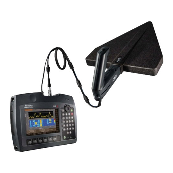
The IDA-3106 can be used outdoors even under difficult environmental conditions thanks to its robust casing, controls that can also be operated when wearing Figure 1: IDA-3106 in field use gloves, and rechargeable batteries that can be hot swapped. IDA-3106 Narda... -
Page 11: The Antenna Handle
1.2 The antenna handle The antenna handle The antenna handle is designed for attaching to the Narda directional antennas, providing an ergonomic grip for the antenna. An electronic 3-axis compass, a 20 dB preamplifier, and a button for starting measurements are all built in to the handle. -
Page 12: Narda Directional Antennas
Narda directional antennas Three Narda directional antennas that are specially matched to the IDA-3106 and which fit the antenna handle are available. They cover the frequency range from 20 MHz to 6 GHz. A highly sensitive loop antenna is also available as an accessory for covering the lower frequency range from 9 kHz to 30 MHz. -
Page 13: Pc Connection
Figure 7: Loop antenna, frequency range 9 kHz to 30 MHz PC connection The device IDA-3106 can be connected to a PC via the optical interface or the USB port (Mini B type). This allows access to the device functions and measurement results. -
Page 14: About This Operating Manual
User interface language This operating manual uses English terminology to describe the user interface. The user interface of the IDA-3106 can however be displayed in other languages. If you select another language for the user interface, the displayed terms will differ from the ones described in this manual. - Page 15 Indicates a danger that will result in death or DANGER severe injury. Warning format All warnings have the following format: WARNING TERM Type and source of danger Consequences of ignoring the warning Action needed to avoid danger Narda IDA-3106...
- Page 16 This line is omitted if the function is on the topmost level. Example: Multi-Channel Power • Select Menu Important additional information or details of special features or situations. Note: IDA-3106 Narda...
-
Page 17: Important Safety Instructions
Proper use (page 10) Improper use (page 11) General hazards (page 11) Dangers due to electromagnetic fields (page 12) AC adapter / charger (page 14) Rechargeable batteries (page 15) Faults and unusual stresses (page 18) 2.10 Proper disposal (page 18) Narda IDA-3106... -
Page 18: Using This Operating Manual
The device may only be used under the conditions and for the purpose for which it was constructed. The IDA-3106 is designed for measuring and evaluating electromagnetic fields. Only use the device under the conditions and for the purpose for which it was constructed. -
Page 19: Improper Use
2.4 Improper use Improper use The IDA-3106 is not a warning device that gives indication of the presence of dangerous fields by means of visible or audible signals. Always consider the device as a measuring device, never as a warning device. -
Page 20: Dangers Due To Electromagnetic Fields
Always select the largest available or the most suitable frequency range. Always carefully observe the actual measurement value display when approaching unknown fields. In case of doubt, use an additional wideband warning device such as RadMan or Nardalert from Narda Safety Test Solutions. IDA-3106 Narda... - Page 21 Do not handle or use a device that is opened or that is visibly damaged. Only use the accessories supplied with and designed for the IDA-3106. NOTICE Malfunction Improper use, damage, and unauthorized repairs can impair the accuracy and function of the device ...
-
Page 22: Ac Adapter / Charger
AC adapter charger is cold and is brought into a warm room, it must be allowed to dry out before you connect it up. Only use the AC adapter / charger indoors and at temperatures between 0 °C and +40 °C. IDA-3106 Narda... -
Page 23: Rechargeable Batteries
2.8 Rechargeable batteries Rechargeable batteries The IDA-3106 is fitted with a replaceable rechargeable Lithium-ion battery so that you can use it independently of AC line power. The device also has an internal NiMH buffer battery which will power the device for 10 seconds so you can replace the rechargeable battery during operation (hot swap). - Page 24 Make sure that you are upwind of the fire before attempting to extinguish it to prevent inhaling poisonous vapors. Irritation of the eyes, skin, and respiratory tract can occur due to smoke or vapors from a burning battery (see next section). IDA-3106 Narda...
- Page 25 Only charge the batteries in accordance with the instructions in this manual using the specified charger unit. The charging temperature must be between 0 °C and +40 °C. Only discharge the battery between -20 °C and +60 °C. Narda IDA-3106...
-
Page 26: Faults And Unusual Stresses
In the European Union, all electronic measuring systems purchased from Narda after August 13, 2005 can be returned at the end of their useful life. For more information, please contact your Narda distributor. IDA-3106... - Page 27 Batteries must not be disposed of in household waste, but must be disposed of separately from the product in accordance with the applicable regulations. They can be returned free of charge to the appropriate collection points, your dealer or directly via Narda. Please discharge the batteries before disposal. 2.10.3...
- Page 28 2 Important Safety Instructions IDA-3106 Narda...
-
Page 29: Connecting Up And Starting To Use The Device
Connecting Up and Starting to Use the Device This chapter describes field and laboratory use of the IDA-3106, as well as the general concept of the device. Unpacking the device (page 22) Device overview (page 23) Power supply (page 27) -
Page 30: Unpacking The Device
The device is not ready for use until it has reached a temperature that is within the guaranteed operating range of -10 to +50 °C. IDA-3106 Narda... -
Page 31: Device Overview
Device overview 3.2.1 Case contents No. Element No. Element Operating manual, Antenna 2 software CD IDA Basic Unit Charger dock (accessory) Spare battery (accessory) AC adapter charger(s) Antenna 1 Antenna handle Arm support, headphones, Antenna 3 carrying strap, USB cable... - Page 32 • LED red: Battery is charging. Charge indicator • LED green: Charging cycle finished or AC adapter / charger still connected to device charging socket. Switches device on or off (hold down key). On/Off key Context-dependent, function selection, changing settings. Horizontal softkeys IDA-3106 Narda...
- Page 33 No. Element Function / Explanation 12-pole socket for connecting the control cable (for Multi-pin connector automatic recognition of antenna and cable when using a Narda antenna or Narda cable). Antenna connecting socket N connector 3.2.4 Device side panel with battery compartment No.
- Page 34 USB, Mini-B type For connecting the AC adapter / charger supplied Charging socket Slot for microSD memory card Card slot For connecting to a local area network Ethernet (IDA 2, 3106/02 and later). Data transfer is not indicated visually. IDA-3106 Narda...
-
Page 35: Power Supply
Charging the battery pack A complete recharge takes about 5.5 hours. You must use the AC adapter / charger provided or the optionally available charging dock to recharge the battery pack. Narda IDA-3106... - Page 36 The AC line voltage must be the same as the operating voltage of the AC adapter / charger. 1. Connect the AC adapter / charger to the charge socket of the IDA-3106. 2. Connect the AC adapter / charger to the AC line.
- Page 37 Proper disposal on page 18). 3.3.3 Operation from AC adapter / charger The IDA-3106 can also be operated and powered from the AC adapter / charger. However, this is not recommended for general use, as the measurement characteristics can be significantly affected by the presence of the power supply cable in the electromagnetic field when the IDA-3106 is operated with the AC adapter / charger connected to it.
-
Page 38: Fitting The Narda Directional Antennas
Fitting the Narda directional antennas This section describes how to fit Narda directional antennas and the handle on to the IDA-3106. Full use of all the functions of the IDA-3106 is only possible when you use the Narda antenna handle. -
Page 39: Attaching Other Narda Antennas
Connecting a Narda directional antenna to the handle Narda directional antennas can be attached to the handle in positions that are at angles of 90 degrees to each other. This makes it quick and easy for you to change the polarization plane of the antenna. - Page 40 3 Connecting Up and Starting to Use the Device 3.5.1 Attaching the Narda antenna directly to the Basic Unit 1. Place the Basic Unit in a vertical position. 2. Plug the N connector on the antenna on to the N connector of the Basic Unit.
- Page 41 3.5 Attaching other Narda antennas 3.5.2 Connecting a Narda antenna to the Basic Unit using a Narda cable Connecting a Narda cable to the IDA-3106 1. Place the Basic Unit in a vertical position. 2. Plug the N connector on the cable on to the N connector of the Basic Unit.
-
Page 42: Using Cables And Antennas From Other Manufacturers
IDA-3106 manually using the PC software (see description below). Manually entering data for third party components You first have to enter the data in the PC software IDA Tools and then transfer them to the IDA-3106. To enter the data: 1. - Page 43 Connecting third party antennas to the handle Antennas fitted with a coaxial N connector can also be used as directional antennas with the Narda handle by means of the Antenna Adapter 3100/15. Connecting the antenna: The configuration data for the antenna have been uploaded.
- Page 44 The antenna adapter may detach from the antenna handle when it is rotated rapidly if the directional antenna weighs more than 1 kg or is longer than 60 cm. Pan the directional antenna slowly. Use a tripod if necessary. IDA-3106 Narda...
-
Page 45: Using The Carrying Strap
3.7 Using the carrying strap Using the carrying strap The strap allows you to effortlessly carry the IDA-3106 hands free, so you can use one hand to align the antenna and the other to operate the measuring instrument. You can also clip the antenna handle to the strap if you need to carry the equipment over a long distance or you want to use both hands to operate the instrument. - Page 46 1. Put on the carrying strap. Tighten the two shoulder straps and the chest strap to adjust it so it fits comfortably. 2. Attach the strap holders to the loops on the sides of the Basic Unit (4 loops, one on each corner). IDA-3106 Narda...
- Page 47 4. Adjust the strap so that the Basic Unit is at the right height and angle for you. It should be comfortable and the display should be easy to read. You can also clip the antenna handle to the strap. Narda IDA-3106...
- Page 48 Basic Unit. 6. You can leave the Basic Unit attached to the carrying strap, even when it is stored in the hard case. IDA-3106 Narda...
-
Page 49: Operation And Basic Settings
This chapter describes the controls and connectors on the device. Controls (page 42) Switching the device on and off (page 45) Switching stealth mode on and off (page 45) LCD screen elements (page 46) Fundamental operating steps (page 50) Narda IDA-3106... -
Page 50: Controls
4 Operation and Basic Settings Controls The following controls are provided for operating the IDA-3106: • Rotary control knob • Hardware keys (referred to as keys in this manual) • Software keys (referred to as softkeys in this manual) • Button on the antenna handle 4.1.1... - Page 51 Move screen contents right (see Navigating and zooming on page 149). 4.1.3 Softkeys The softkey functions depend on the selected menu level, operating mode, or function. The softkeys are therefore described in the menu and operating mode descriptions. Narda IDA-3106...
- Page 52 Scan Type Discrete with Max Hold Press the button briefly. Start & Reset Max > Add Value > Reset Max > Add Value > ... Press and hold down the button. Stop > Resets the measurement results. IDA-3106 Narda...
-
Page 53: Switching The Device On And Off
To switch to stealth mode: Press the key. The screen display and audio playback switch off. The status display LED flashes briefly every 3 seconds. To switch off stealth mode and revert to measurement operation: Press the key. Narda IDA-3106... -
Page 54: Lcd Screen Elements
• Event display for Auto Save Lower status bar Indicates settings and process analysis; displays error messages. Horizontal softkeys Displayed functions are context-sensitive. Vertical softkeys Displayed functions are context-sensitive. Navigator bar Selected display mode and arrow symbols for navigation IDA-3106 Narda... - Page 55 Antenna used (displayed only if the type is automatically Ant. recognized or has been entered manually). Cable used (displayed only if the type is automatically Cable recognized or has been entered manually). Selected multi-channel table. MCTbl Selected transmitter table. TxTbl Narda IDA-3106...
- Page 56 Progress of measurement (as a check until the first screen Progress display during measurements requiring a lot of processing) Number of measurements No. of Runs made since last measurement start Number of measurements to form average or time to form average IDA-3106 Narda...
- Page 57 Magnifier function is active in Spectrum, Time Domain (Scope) and I⁄Q Analyzer modes. The extra item Hide at Magnifier is provided for this purpose. For more information about this, see Automatically hiding the status bars on page 117. Narda IDA-3106...
-
Page 58: Fundamental Operating Steps
4.5.1 Navigating in the menus The operating modes and functions of the IDA-3106 are arranged in hierarchical menu levels. The diagram below (see Figure 12 on page 50) shows this arrangement using the main menu and some of the functions in mode as examples. - Page 59 Function not available Multi-Channel Power To move backwards or forwards: Press the Extras softkey, then press the Backwards or Forwards softkey. The Forwards softkey is not shown until you have pressed the Backwards softkey at least once. Narda IDA-3106...
- Page 60 You can use the rotary control knob to page through the list. To select an item: 1. Use the rotary control knob or arrow keys to highlight the desired item. 2. Press the OK key to confirm your selection. The new value will be set. IDA-3106 Narda...
- Page 61 The softkeys that are actually available depend on the Select menu that is NOTE: opened. When you have selected the items you want, press the OK key to revert to the measurement display again. Narda IDA-3106...
- Page 62 2. Use the number keys and decimal point key to enter the desired value and enter the desired units using the appropriate softkey. (You can delete digits using the Backspace softkey.) The new value is set and the Select menu closes as soon as you have entered the units. IDA-3106 Narda...
- Page 63 Deletes all characters entered. Delete All Switches between upper and lower case characters: Case • Lower: lower case characters • Upper: upper case characters You can also enter the digits 0 through 9 directly using the numerical keys. NOTE: Narda IDA-3106...
- Page 64 Start Demodulation. 4.5.7 Creating a screenshot You can download the saved screenshots in PNG format from the device using the PC software application IDA Tools. To create a screenshot: 1. Press the Display softkey. 2. Press the Save Screenshot softkey.
-
Page 65: The Main Menu
Menu overview (page 58) Displaying and editing system settings (page 66) Displaying and editing configuration data (page 77) Saving and loading setups (page 85) The memory menu (page 87) The SD Card menu (page 88) Narda IDA-3106... -
Page 66: Menu Overview
5 The Main Menu Menu overview This section describes the two menu levels of the Main menu and the operating modes. The conditions necessary for the indicated softkey to be displayed are shown in brackets. 5.1.1 Main menu IDA-3106 Narda... - Page 67 5.1 Menu overview 5.1.2 Direction Finding Narda IDA-3106...
- Page 68 5 The Main Menu 5.1.3 Spectrum IDA-3106 Narda...
- Page 69 5.1 Menu overview Narda IDA-3106...
- Page 70 5 The Main Menu 5.1.4 Level Meter IDA-3106 Narda...
- Page 71 5.1 Menu overview 5.1.5 Time Domain (Scope) Narda IDA-3106...
- Page 72 5 The Main Menu 5.1.6 I/Q Analyzer IDA-3106 Narda...
- Page 73 5.1 Menu overview 5.1.7 Multi-Channel Power Narda IDA-3106...
-
Page 74: Displaying And Editing System Settings
• Calibrating the internal compass (page 76) • Displaying and selecting Antennas (page 77) • Using external devices (page 78) • Displaying and selecting cables (page 79) • Displaying and creating Multi-Channel Tables (page 79) • Creating and editing Transmitter Tables (page 82) IDA-3106 Narda... - Page 75 3. Press ESC to return to the Main menu. To synchronize the clock to the GPS clock: Press the Sync Time with GPS softkey. The time is synchronized to the GPS clock. Narda IDA-3106...
- Page 76 LCD screen brightness In 5 % steps from 1 % to 100 % Power Save Power save mode, backlight switches off automatically: (Backlight • In steps from 1 min. to 30 min switches off • Never (on permanently) after): IDA-3106 Narda...
- Page 77 1. Use the rotary control knob to highlight the item and select it by pressing OK. 2. Use the rotary control knob to change the setting and press OK to confirm the change or press ESC to cancel the changes. 3. Press ESC to return to the Main menu. Narda IDA-3106...
- Page 78 Unique device identification number Firmware version Device software version Firmware Date Device software date Bootloader Version Bootloader software version Calibration Date Date of last calibration Next Recommended Calibration Date recommended for next calibration Options Option name Option status (Activated / Deactivated) IDA-3106 Narda...
- Page 79 Main Menu • Settings • Device Info Information about the connected antenna is only displayed when you use a NOTE: Narda antenna. The information for the manually selected antenna type is displayed when other antennas are used. Press the Antenna Info softkey.
- Page 80 Main Menu • Settings • Device Info Information about the connected cable is only displayed when you use a NOTE: Narda cable. Press the Cable Info softkey. The cable information is displayed as a list. Table 12: Description of Cable Info list...
- Page 81 Network mask in static Ethernet mode Default Gateway Default gateway in static Ethernet mode TCP Port Transmission control protocol in static Ethernet mode Host Name Unique device identification for the network (cannot be edited) Mac Address Unique network interface designation (cannot be edited) Narda IDA-3106...
- Page 82 The system settings are not reset. To reset the measurement settings: The Main Menu • Setups menu is open. 1. Select Factory Setup using the rotary control knob. 2. Press the OK key. IDA-3106 Narda...
- Page 83 The displayed data is intended primarily for servicing purposes. NOTE: Table 15: Description of Device Diagnostics list Information Description Mainboard Temperature Temperature of main circuit board RF-Board Temperature Temperature of RF circuit board RF-Board Hardware Version RF board hardware version Narda IDA-3106...
- Page 84 Calibrating the internal compass Main Menu • Settings • Service Menu This function is used to calibrate the compass built in to the IDA Basic Unit. This compass is only used for orientation and aligning the maps displayed on the instrument. The calibration routine reduces any distortion of the earth’s magnetic field due to ferrous metals inside the instrument.
-
Page 85: Displaying And Editing Configuration Data
1. Press the Antenna softkey. The available antennas are listed with their characteristic data. The detected antenna type will be displayed when you use a Narda antenna. 2. Use the rotary control knob or arrow keys to highlight the desired item. - Page 86 Cal. Date External device calibration date 1) The Fmin, Fmax parameters are entered using the IDA Tools PC software. 2. Select the desired device and press the OK key. Selecting the device activates it. ExtDev: On is shown in the lower status bar.
- Page 87 Main Menu • Settings Press the Cable softkey. The available cables are listed with their characteristic data. The automatically detected cable type will be displayed when you use a Narda cable. Table 18: Description of Cables list Item Description...
- Page 88 NOTE: You cannot manually enter individual channels or change the channel names. Tables are much easier to create using the IDA-Tools PC software. Tables created using it can be uploaded to the IDA-3106 afterwards. To create a new multi-channel table: 1.
- Page 89 Channel bandwidth 200 kHz Number of channels Number of channels Preferred RBW Preferred resolution bandwidth 50 kHz (200 kHz/4) Editing channels of a multi-channel table Channels in an existing multi-channel table can only be edited using the PC software. Narda IDA-3106...
- Page 90 Table 22: Description of Transmitter Tables list Item Description Short Name Short name (in the display) Long Name Name (in the selection menu) 2. Use the rotary control knob to select an item and press OK to confirm the selection. IDA-3106 Narda...
- Page 91 2. Press the ESC key to exit the menu without making any changes. 3. To edit the transmitters: Use the softkeys as described under Creating a new transmitter table on page 83. 4. Press the ESC key to exit from the table. Narda IDA-3106...
- Page 92 If you have not already done so, you can select the desired Transmitter Table now. 3. Press the Add Transmitter softkey. 4. Where necessary, adjust the center frequency and channel bandwidth using the Fcent and CBW softkeys. 5. Press the Save softkey to add the frequency to the Transmitter Table. IDA-3106 Narda...
-
Page 93: Saving And Loading Setups
Use the rotary control knob to highlight the desired setup and press the Recall Setup softkey or the OK key. The settings saved in the selected setup will be loaded and the display switches to the measurement screen. Narda IDA-3106... - Page 94 The selected setup is deleted. Deleting all setups 1. Press the Delete All Setups softkey. 2. Confirm the action by pressing OK. You can cancel the action by pressing ESC. All setups except the Factory Setup are deleted. IDA-3106 Narda...
-
Page 95: The Memory Menu
• Set comment function • Save data to microSD memory card in csv format • Configure automatic storage (Time Controlled) You can find detailed information about all these functions in chapter 13 Measurement Data Memory on page 219. Narda IDA-3106... -
Page 96: The Sd Card Menu
Use the formatting function to prepare newly purchased microSD memory cards for use with the IDA-3106. The card is formatted using FAT32 with a block size of 4k. To format a memory card: 1. -
Page 97: Common Functions
Using the Magnifier function (page 114) 6.12 Using Multi-Channel Tables (page 117) 6.13 Demodulating signals (Audio) (page 118) 6.14 Setting the noise threshold (Noise Thresh.) (page 123) 6.15 Measuring with multiple axis antennas (Axis) (page 124) 6.16 Changing the operating mode (page 125) Narda IDA-3106... -
Page 98: Notes On This Chapter
• The system settings for: Language, Battery Type, Time Zone, Daylight Saving Time, Magnetic Declination. You can reset the system settings (Settings) and measurement settings (Factory Setup) separately. You can find information about this under Resetting all device settings on page 74. IDA-3106 Narda... -
Page 99: Setting The Center Frequency (Fcent)
Turn the rotary control knob to the right / left to increase / decrease the center frequency. The change is applied immediately. The Fcent window closes 3 seconds after you stop turning the rotary control knob. Narda IDA-3106... - Page 100 Press the OK key to set the new value. IDA-3106 Narda...
- Page 101 1. Press the Set Fstart & Fstop or Set Fcent & Fspan softkey until the desired setting method is displayed. The labels on the Fstart / Fstop and Fcent / Fspan softkeys also change to match the selected setting method. Narda IDA-3106...
-
Page 102: Setting The Bandwidth (Rbw / Cbw)
Time Domain (Scope) I⁄Q Analyzer Multi-Channel Power The resolution bandwidth (RBW) or channel bandwidth (CBW) allow you to select a narrow frequency range with the desired bandwidth from a wideband spectrum and to suppress the remaining signal components. IDA-3106 Narda... - Page 103 Bandwidths from 100 Hz up to 32 MHz are available. Mode Filter type Spectrum Gaussian Multi-Channel Power Gaussian Direction Finding Steep channel filter Level Meter Steep channel filter Time Domain (Scope) Steep channel filter I⁄Q Analyzer Steep channel filter Narda IDA-3106...
-
Page 104: Setting The Video Bandwidth (Vbw)
To set the integration time T-RMS directly: 1. Press the BW softkey, followed by the Set T-RMS softkey. The VBW softkey label changes to T-RMS. 2. Press the T-RMS softkey. The Select RMS Integration Time (T-RMS) entry box opens. IDA-3106 Narda... -
Page 105: Setting The Reference Level (Reference Level)
Y-Scale Ref parameter in the Display menu. To set the reference level: Press the Reference Level softkey. You can now select the reference level as follows: • Manual reference level selection • Automatic reference level search (RL Search) Narda IDA-3106... - Page 106 Reference Level is changed (RL +5 dB displayed value increases by +5 dB as well). The selected reference level applies to all operating modes and does not NOTE: have to be set again if you change operating mode. IDA-3106 Narda...
- Page 107 Press the ESC key if you want to cancel the process. NOTE: RL Search Type The IDA-3106 provides two types of reference level search which can be selected using the RL Search Type softkey (toggle function): • Sensitive: This type is suitable for all largely static signals.
- Page 108 OVERDRIVEN is shown in the display (in the part above the lower status line, next to the axis setting). In this case, you should increase the Reference Level (RL) and disable the preamplifier if necessary. IDA-3106 Narda...
-
Page 109: Selecting The Trace Type (Trace)
3. When you have made your selection, press the OK key. It is recommended to just select the trace type Act if fast fluctuating signals Tip: shall be displayed. In this case the display is refreshed with a particular high rate. Narda IDA-3106... - Page 110 Reset measurement values You can reset the values for Max, Avg, and Min: • Reset All: Resets all the above-mentioned measurement values. • Reset Min & Max: Resets the Minimum Hold (Min) and Maximum Hold (Max) measurement values only. IDA-3106 Narda...
-
Page 111: Changing The Displayed Units (Unit)
Changing the displayed units (Unit) The frequency range that can be set is determined by the selected units when IDA antennas are used. Measurements are only possible within the specified frequency range of the antenna if units of field strength or power density are selected (see Table 27). - Page 112 The top menu level of the operating mode is displayed. 1. Press the Display softkey, them press the Unit softkey. 2. Use the rotary control knob to highlight the desired unit and press the OK key. The selected unit is saved. IDA-3106 Narda...
-
Page 113: Adjusting The Y Axis (Y-Scale)
1. Press the Y-Scale Ref softkey. 2. Press the Y-Scale Ref fix softkey until On is shown. The Y axis is fixed. 3. Press OK or ESC to exit from the menu. Narda IDA-3106... -
Page 114: The Marker Function
• Automatic peak tracking (can be disabled) • Rotary control knob with acceleration function The marker is not restricted by the pixel resolution of the screen, so it NOTE: always provides the full measurement data resolution of approximately RBW/2. IDA-3106 Narda... - Page 115 Active marker (Marker A is active in the example). Selects whether the marker is shown even after you exit the Marker menu. Display type: Single marker or difference marker You can set the marker evaluation properties under Marker Settings. Narda IDA-3106...
- Page 116 Peak Tracking: Activates / deactivates peak tracking or highest level tracked Changing the marker evaluation settings You can find information about setting a threshold or a minimum peak excursion or peak tracking value under Changing the marker evaluation settings (Marker Settings) on page 113. IDA-3106 Narda...
- Page 117 “Val” is shown after the trace type / detector (e.g.: Max Val: 105.8 mV/m). Another special feature of the peak marker is that the frequency is tracked and follows the peak value (Peak Tracking: On). Narda IDA-3106...
- Page 118 – The ratio B/A is given in % for Unit = V/m, A/m, W/m , mW/cm – The difference B-A is given in dB for log. units such as dBµV or dBV/m Graphical display of the marker positions. IDA-3106 Narda...
- Page 119 7. Move Marker B to the desired position (either manually or using the Peak functions). The selected frequencies and the corresponding measured values along with the difference are displayed in the upper status bar. Narda IDA-3106...
- Page 120 Figure 22: Display of marker data in the upper status bar. To activate the display function: The Marker sub-menu is active. 1. Press the Keep Marker softkey until Keep Marker: On is shown. 2. Press the ESC to return to the measurement screen. IDA-3106 Narda...
- Page 121 To select a Peak Excursion value: 1. Press the Peak Excursion softkey until On appears. The function is activated. 2. Press the Set Excursion softkey, select a value with the rotary control knob, and press OK to make the setting. Narda IDA-3106...
-
Page 122: Using The Magnifier Function
X axis of the enlarged area. One of the great advantages of the IDA is its very high frequency and time resolution. Using the Magnifier function, you can display and analyze both the entire spectrum and a section of it at full resolution. - Page 123 4. Press the Magnification: Low/High softkey to set the desired magnification. Figure 23: Split screen display for Magnifier function No. Function / Explanation Magnifier window Marker shown in Magnifier window at center of X axis Overview window (Spectrum, Time Domain (Scope), I⁄Q Analyzer) Narda IDA-3106...
- Page 124 Peak marker goes above or below a threshold of ±1/4 of the current Magnifier span. This avoids continuous jumping of the display. • The Keep Marker function also keeps the Magnifier settings in the main view when you exit the Marker menu. IDA-3106 Narda...
-
Page 125: Using Multi-Channel Tables
1. If necessary, change the multi-channel table using the Select Multi-Ch. Table softkey. 2. Press the Select Channel softkey. A list of the available channels is displayed. 3. Use the rotary control knob to select an item and press OK to confirm the selection. Narda IDA-3106... -
Page 126: Demodulating Signals (Audio)
• FM, AM, CW: up to 200 kHz max. • LSB, USB: up to 16 kHz max. CW demodulation is used to demodulate clocked carrier signals (Morse signals) and generates a 1 kHz sinewave when the carrier signal is active. IDA-3106 Narda... - Page 127 3. Use the rotary control knob to select the desired type and press OK to confirm. The demodulated signal content is output from the loudspeaker or from headphones, if connected. 4. To deactivate demodulation, press the Demodulation softkey, select Off with the rotary control knob and press OK to confirm. Narda IDA-3106...
- Page 128 You can also set a fixed value. Demodulation can also be used after exiting from the Audio menu. If you want to do this, use the decimal point key of the number keys to interrupt demodulation. IDA-3106 Narda...
- Page 129 2. Use the rotary control knob to select the desired value and press OK to confirm. 3. To deactivate noise suppression press the Squelch softkey, select Off with the rotary control knob (last item in the list), and press OK to confirm. Narda IDA-3106...
- Page 130 Ethernet. See Demodulation types (Demodulation) on page 118 for details of demodulation types and bandwidth. For smooth operation of digital audio streaming at 200 kHz RBW and Tip: 32 kHz sample rate disconnect the antenna control plug of the antenna handle. IDA-3106 Narda...
-
Page 131: Setting The Noise Threshold (Noise Thresh.)
The noise threshold must be activated before you can select a value. 1. Press the Reference Level softkey and then the Noise Thresh. softkey. 2. Use the rotary control knob to set the desired input sensitivity and then press the OK key. The threshold value is set. Narda IDA-3106... -
Page 132: Measuring With Multiple Axis Antennas (Axis)
I⁄Q Analyzer • Axis Multi-Channel Power • Axis You can only make measurements in a single axis with the IDA-3106 even if a multiple axis antenna is connected. The Axis Mode selection window allows you to select the axis for measurement. In this way you can measure all three axes one after the other and save the results separately without having to reposition the antenna. -
Page 133: Changing The Operating Mode
CBW is set. 6.16.2 Changing the operating mode from the Main menu 1. Press the MENU key until the Main menu is displayed. 2. Press the softkey for the desired operating mode. Narda IDA-3106... - Page 134 6 Common Functions IDA-3106 Narda...
-
Page 135: Direction Finding Mode
Operating mode specific functions (page 129) Manual Bearing (page 131) Horizontal Scan (page 134) Localizing a signal source (Outdoor) (page 139) Exchanging bearings between instruments (page 142) The Map menu (page 143) Finding the location of a signal scource (Indoor) (page 154) Narda IDA-3106... -
Page 136: About Direction Finding Mode
Direction Finding mode is used to determine the direction (bearing) and location of a signal source. As this mode requires compass information, you must use the Narda antenna handle for measurements. This supplies the measuring instrument with information about the actual position of the antenna in addition to the measurement signal. -
Page 137: Operating Mode Specific Functions
3. Use the rotary control knob to make the selection and press OK to confirm. When you press the Detector softkey, other softkeys appear that allow you NOTE: to reset the maximum value (Reset Max) or all values (Reset All). Reset All resets the maximum values and the average values. Narda IDA-3106... - Page 138 The maximum value (RMS or Peak) that occurred since the start of the measurement is also shown. The maximum value is shown as a red line in the bar graph. This display is only possible for Manual Bearing (see section 7.3 on page 131). IDA-3106 Narda...
-
Page 139: Manual Bearing
(angle above the horizon) of the signal source as well as the signal polarization. To select the Manual Bearing function: Press the Horizontal Scan softkey until Off appears. Figure 24: Direction Finding mode, Manual Bearing measurement screen. Narda IDA-3106... - Page 140 In Bargraph mode, the measured signal level is also output as an audible signal. The pitch corresponds to the signal strength. • The stronger the signal, the higher the tone. • The weaker the signal, the lower the tone. IDA-3106 Narda...
- Page 141 1. Press the Audio softkey, then press the Tone Search softkey. 2. Use the rotary control knob to select the desired setting and press OK to confirm. 3. To deactivate the audible signals, select Off using the rotary control knob and press OK to confirm. Narda IDA-3106...
-
Page 142: Horizontal Scan
(1 = 100 % signal strength). The display allows you to more easily see the difference between the received signal and the reflections that occur. The IDA-3106 automatically calculates the bearing of the signal source based on the horizontally measured values. - Page 143 Continuous Horizontal Scan (Continuous) Direction Finding (Horizontal Scan: On) The IDA-3106 continuously measures the signal level and saves the values as the antenna is panned horizontally. The measurement is stopped manually after a sufficient number of measured values has been obtained.
- Page 144 If you pan the antenna too quickly or tilt it by more than 15° horizontally or NOTE: vertically (elevation: ±15°, polarization: ±15°) Azimuth uncertain will be displayed in red to indicate that deviations can occur in the bearing that is determined. IDA-3106 Narda...
- Page 145 If you pan the antenna too quickly or tilt it by more than 15° horizontally or NOTE: vertically (elevation: ±15°, polarization: ±15°) Azimuth uncertain will be displayed in red to indicate that deviations can occur in the bearing that is determined. Narda IDA-3106...
- Page 146 The red arrow moves to the manually specified direction (green arrow) when you press the softkey. 2. Press the SAVE key on the Basic Unit to save the measurement results. A window shows the save process. IDA-3106 Narda...
-
Page 147: Localizing A Signal Source (Outdoor)
The Distance function in the Map menu is provided for this purpose. This method does require that the source signal level is constant and that reflections are small (this is critical in street canyons, for example). Narda IDA-3106... - Page 148 Step 1: Start localization Press the Localization softkey. The softkey shows On and glows red. All the measurement results saved until you press the softkey again are saved in the same data set and used for subsequent localization. IDA-3106 Narda...
- Page 149 The bearing results from the other instruments can then be entered into one instrument. You can find information about this under Exchanging bearings between instruments on page 142. Narda IDA-3106...
-
Page 150: Exchanging Bearings Between Instruments
Direction Finding • External Bearing You will normally only use one IDA-3106 and will therefore have to move to a different location to take bearings from different points. If more than one instrument is available, you can have measurements made at several locations simultaneously and exchange the results or transfer them to one IDA-3106 for evaluation. -
Page 151: The Map Menu
– Loc. Mode: Indoor = Indoor localization – Loc. Mode: Outdoor = Outdoor localization The information bar in the measurement menu indicates the selected type: • Direction Finding (Outdoor) = Outdoor localization • Direction Finding (Indoor) = Indoor localization Narda IDA-3106... - Page 152 To display bearings during a localization in progress: Take bearings as described in sections 7.3 on page 131 and 7.4 on page 134, and press the Map softkey without closing the localization. Press ESC to return to the measurement menu. IDA-3106 Narda...
- Page 153 • Index 11.1: consecutive index number • LOC: data type: Localization • Date: Date and time when measurement was made Page forwards or backwards in the data memory without switching to the Memory menu Display is in recall mode Narda IDA-3106...
- Page 154 > Recall Data Set. 4. Press the Add to Localization softkey. The bearing is added to the opened localization. 5. If desired, add further bearings. Then press the Localization softkey to close the localization and save it. IDA-3106 Narda...
- Page 155 Suitable maps can be downloaded free from the Internet using the Narda MapTools PC software, and then configured on the memory card (see Loading maps using Narda MapTools on page 148). If a map for the displayed area at the selected zoom level is not available, a plain color background will be displayed.
- Page 156 The selected map area is saved as an offline map on the PC. The next step is to connect the microSD card of the IDA to the PC using the USB adapter supplied, select a section of the offline map and copy it to the memory card.
- Page 157 Depending on the version of your instrument a compass rose is located in the upper right corner of the screen as an aid to orientation. The actual direction is indicated by a red arrowhead related to magnetic north. Narda IDA-3106...
- Page 158 You can use the All Transmitters softkey to display all transmitter locations NOTE: for all frequencies simultaneously as different colored circles. Measurement locations and bearings are not then displayed. Details (e.g. geo-coordinates) are displayed in each case for the transmitter that you highlight. IDA-3106 Narda...
- Page 159 An excluded bearing is shown in gray. 5. To reactivate all excluded bearings, press the Enable all Bearings softkey. 6. To delete a bearing, press the Delete Bearing softkey. The selected bearing is deleted from the localization. Narda IDA-3106...
- Page 160 3. To hide your own location again, press the Point of View softkey again until Off is displayed. An arrow in the black dot indicates the direction in which you are holding the NOTE: handle (and antenna) when the antenna handle is plugged in. © OpenStreetMap contributors, CC BY-SA IDA-3106 Narda...
- Page 161 An uncertainty of 5° is selected in this example. To change the bearing uncertainty: 1. Press the Bearing Uncertainty softkey in the Average Position display. 2. Select a value using the rotary control knob and press OK to confirm. Narda IDA-3106...
-
Page 162: Finding The Location Of A Signal Scource (Indoor)
To localize signal sources in rooms despite this fact, the IDA-3106 allows you to define the ground area of the room by means of four corners (A – D) and to specify its orientation by its azimuth. - Page 163 D. The room sides must be at right angles to each other. (The reference points normally correspond to the room corners.) 2. Press the Map softkey in Direction Finding mode, then press the Loc. Mode softkey until Indoor is shown. Narda IDA-3106...
- Page 164 Localization softkey to close the localization. 7. A closed localization is not shown in the Map menu any more and must be recalled from the memory when required (see Loading saved localizations and adding bearings on page 145). IDA-3106 Narda...
- Page 165 8. Press the Average Position softkey to display the calculated signal location. X indicates the horizontal distance and Y the vertical distance from point A. Figure 33: Direction Finding Indoor: Bearings and calculated transmitter location. header line X, Y: distance of signal location from point A. Narda IDA-3106...
- Page 166 7 Direction Finding Mode IDA-3106 Narda...
-
Page 167: Spectrum Analysis Mode
About Spectrum Analysis mode (page 160) The Spectrum measure menu (page 161) Comparing spectra (Delta Spectrum) (page 166) Displaying the time characteristic (Spectrogram) (page 168) The Spectrogram Marker (page 171) Narda IDA-3106... -
Page 168: About Spectrum Analysis Mode
Results are always recorded and saved for all three detector types. Spectrum and Spectrogram can be displayed individually or in two windows one above the other. To select a function: Press the Measurement softkey. Figure 34: The Measurement menu: The selected function is highlighted in color. IDA-3106 Narda... -
Page 169: The Spectrum Measure Menu
6 Common Functions on page 89. Figure 35: Spectrum display The Spectrum Measurement menu also includes further evaluation functions as follows: • Peak Table: Lists the highest peaks • Single Channel Power: Determines wideband values These functions are described below. Narda IDA-3106... - Page 170 Channel to which the peak (frequency value) belongs. Transmitter If a transmitter table is selected, the transmitter names will be shown here. Trace types The columns displayed depend on the trace types that have been selected (see next section). IDA-3106 Narda...
- Page 171 The measured values are shown relative to the selected reference trace in relative display mode. Press the Results softkey: – For absolute values: The softkey label must show Absolute. – For relative values: The softkey label must show Relative. Narda IDA-3106...
- Page 172 The type of entry method is selected using the Entry softkey: • Numerical: Numerical entry using the number keys and decimal point key in the keypad. • Graphical: The rotary control knob is used to enter the frequency limits. IDA-3106 Narda...
- Page 173 The diamonds of both markers will be filled out in black if graphical entry is selected. 4. Use the rotary control knob or the number keys to specify the frequency band and then press the OK key to save the setting. Narda IDA-3106...
-
Page 174: Comparing Spectra (Delta Spectrum)
All the displayed spectra are shown relative to the reference spectrum when the function is activated (softkey highlighted in color). If a reference trace is not present a window opens, allowing one of the current traces to be set as reference. IDA-3106 Narda... - Page 175 To use the reference spectrum: Press the Delta Spectrum softkey in the Measurement menu (the softkey is highlighted in color when the function is activated). All the displayed spectra are shown relative to the reference spectrum. Narda IDA-3106...
-
Page 176: Displaying The Time Characteristic (Spectrogram)
Spectrogram mode allows you to display the variation in the signal strength of a spectrum versus time. To display the spectrogram: Press the Measurement softkey. Two display modes are available: – Spectrogram: Only the spectrogram is displayed. – Spectrogram & Spectrum: The spectrogram and the spectrum are displayed. IDA-3106 Narda... - Page 177 Spectrum window, i.e. 10 to 90 dBµV/m in the example shown. You can adjust the colored display using the Y-Scale Range and Y-Scale Ref parameters in the Display menu (see Adjusting the Y axis (Y-Scale) on page 105). Softkey for selecting the Time Resolution. Narda IDA-3106...
- Page 178 You can therefore switch between the detector types at any time and the results shown immediately, without the need for a new measurement. To select a detector: Press the Detector softkey, select a type using the rotary control knob and press OK to set it. IDA-3106 Narda...
-
Page 179: The Spectrogram Marker
The Spectrogram Marker has some additional functions: • Navigation: Moves the marker along the frequency or time axis. • Delta Marker: Displays the differences between markers at the same time, at the same frequency, or freely settable markers. Narda IDA-3106... - Page 180 • Frequency: The markers can be moved on the frequency axis. The marker is moved using the rotary control knob. Detector: Selects a detector: RMS, +Peak, -Peak To open the Spectrogram Marker sub menu: Press the Marker Settings softkey. IDA-3106 Narda...
- Page 181 4. Select Active Marker = B. 5. Set Marker B to the second frequency. The associated values are displayed in the Marker bar. If you select Navigation = Time, you can move both markers together along Tip: the time axis. Narda IDA-3106...
- Page 182 Setting a threshold (Peak Threshold) See Changing the marker evaluation settings (Marker Settings) on page 113. 8.5.3 Setting a minimum signal peak excursion (Peak Excursion) See Changing the marker evaluation settings (Marker Settings) on page 113. IDA-3106 Narda...
-
Page 183: Level Meter Mode
This chapter describes Level Meter mode. Following a short introduction to the operating mode, an overview of the measurement screen is given along with information about the settings. About Level Meter mode (page 176) Display overview (page 177) Operating mode specific functions (page 178) Narda IDA-3106... -
Page 184: About Level Meter Mode
The Peak detector values (for brief pulsed signals) and RMS detector values (for variable signals) are displayed simultaneously. One advantage of Level Meter mode is that the measurement is in real time and there are no time gaps. IDA-3106 Narda... -
Page 185: Display Overview
A new maximum level can also be indicated by a beeper. To do this, you must activate the Beep on new Maximum function at Main Menu/Settings. To activate the beeper: See Editing device-specific settings on page 68. Narda IDA-3106... -
Page 186: Operating Mode Specific Functions
To select the averaging time: 1. Press the Detector softkey. 2. Press the RMS Average Time softkey. 3. Use the rotary control knob to select the desired averaging time and then press the OK key to make the setting. IDA-3106 Narda... - Page 187 (complete bar), the instrument refreshes the resulting value using the new measurement results and discards the oldest results (progressive averaging over time). RMS Max Displays the maximum value of the averaged values that has occurred since the measurement started. Narda IDA-3106...
- Page 188 9 Level Meter Mode IDA-3106 Narda...
-
Page 189: Time Domain (Scope) Mode
Time Domain (Scope) Mode In Time Domain (Scope) mode, the IDA-3106 measures continuously and selectively at a fixed frequency setting. This enables it to also detect brief peaks, e.g. from pulsed radar equipment. The operating mode is also suitable for timer-controlled measurements. -
Page 190: About Time Domain (Scope) Mode
10 Time Domain (Scope) Mode 10.1 About Time Domain (Scope) mode In Time Domain (Scope) mode, the IDA-3106 measures selectively at a pre-selected frequency and displays the result as a graph continuously versus time (Zero Span operation). The trace shape corresponds here to the magnitude of the signal level, which is recorded without any gaps within the displayed time range. -
Page 191: Display Overview
• vertical line = Trigger Delay Trace / Detector (depends on the selected measurement function/ sub menu) • Act = real-time measurement • +Pk/RMS/-Pk = compressed values over longer measurement periods Measurement “frozen” by trigger function (see Table 36 on page 194) Narda IDA-3106... -
Page 192: Selecting Measurement Parameters
62,500 +Peak, RMS, 24 h Time Span / n -Peak Scope Some examples of channels and the appropriate settings of these parameters are also given in the section Measurement parameter examples on page 187. IDA-3106 Narda... - Page 193 Setting the channel bandwidth (CBW) You must choose a channel bandwidth that allows the entire signal to be captured. The maximum possible time resolution (1/CBW) results from the bandwidth setting. See Setting the bandwidth (RBW / CBW) on page 94. Narda IDA-3106...
- Page 194 3. Press the Trace / Detector softkey, select an item using the rotary control knob, and press OK to set the selection. If you selected High Resolution Scope sub mode, the Trace/ Detector softkey is not shown. Only the detector Act is possible. IDA-3106 Narda...
-
Page 195: Measurement Parameter Examples
Function / Setting Center frequency of GSM channel to be observed, Fcent e.g. 931.1879 MHz 200 kHz Measurement High Resolution Scope > 4.6 ms, selected: 5 ms Time Span Automatically set from 1/CBW = 5 s Time Resolution Narda IDA-3106... - Page 196 Function / Setting e. g. Channel 0: 1897.344 MHz Fcent 1728 kHz –> selected: 2 MHz Measurement High Resolution Scope 24 timeslots x 417 s = 10 ms Time Span Automatically set from 1/CBW = 500 ns Time Resolution IDA-3106 Narda...
- Page 197 20 MHz Measurement Long-Time Scope Detector +Peak/RMS/-Peak Time Span 1 ms Time Resolution 400 ns Because of the large spread of possible setting values, it is not possible to specify fixed values. However, two representative examples are given below. Narda IDA-3106...
- Page 198 2. Examples of different settings, CBW = 20 MHz and Measurement = Long-Time Scope: • Time Span = 1 ms • Time Span = 5 ms • Time Resolution = 400 ns • Time Resolution = 1400 ns IDA-3106 Narda...
- Page 199 2. Switch to Time Domain (Scope) mode. 3. Settings in the example: – Fcent = 433.942 MHz – CBW = 100 kHz – Measurement = High Resolution Scope – Time Span = 10 ms – Time Resolution = 1/CBW = 10 µs Narda IDA-3106...
-
Page 200: Using The Trigger Function
– Negative delay values cause the signal characteristic prior to the trigger event to be displayed (pre-trigger). – Positive delay values cause the signal characteristic after the delay following the trigger event to be displayed. The trigger event is outside the display area. IDA-3106 Narda... - Page 201 When you have selected Single or Multiple, the readiness of the trigger function is indicated at the lower right of the measurement screen: Figure 44: Time Domain (Scope) operating mode, trigger function Single selected but not yet started Narda IDA-3106...
- Page 202 1. Press the Trigger Mode softkey and select Time Controlled. The message Waiting for Arm appears on the screen. 2. Press the Start Date softkey and enter the desired date. You can enter the current date automatically by pressing the Current Date softkey. IDA-3106 Narda...
-
Page 203: Saving Measured Values Automatically
The trigger function is active; the Suspend Auto Save softkey is displayed. The measurement is saved when the trigger event occurs and the time specified by Time Span has elapsed. To suspend auto saving: Press the Suspend Auto Save softkey. Narda IDA-3106... -
Page 204: Measuring The Duty Cycle And Time Domain Power
The Duty Cycle function corresponds to the signal duty cycle if the signal shape is rectangular. The values of Pavg and Ppeak are also displayed in the Marker bar. The measured value for Pavg is often referred to as the Time Domain Power. IDA-3106 Narda... - Page 205 – Numerical: Press one of the softkeys and set the value. The selected values as well as the ratio Pavg/Ppeak are shown in the upper part of the screen. Narda IDA-3106...
- Page 206 10 Time Domain (Scope) Mode IDA-3106 Narda...
-
Page 207: I/Q Analyzer Mode
11.1 About I⁄Q Analyzer mode (page 200) 11.2 Display overview (page 202) 11.3 Selecting measurement parameters (page 205) 11.4 Using the trigger function (page 209) 11.5 Saving measured values automatically (page 209) Narda IDA-3106... -
Page 208: About I⁄Q Analyzer Mode
11.1 About I⁄Q Analyzer mode Measurement method: In I⁄Q Analyzer mode, the IDA-3106 measures a pre-selected frequency selectively using the selected channel bandwidth (CBW) (Zero Span operation). Only the I/Q data resulting from the complex output signal of a base-band demodulation are obtained; this is referred to as I/Q demodulation. - Page 209 To select a view: Press the View softkey and select a view. Magnitude corresponds to the results of Time Domain (Scope) mode / High NOTE: Resolution Scope sub mode (see About Time Domain (Scope) mode on page 182 for information). Narda IDA-3106...
- Page 210 Trigger time point indication (not needed for Free Run) Trigger message (see Table 36 on page 194). Display during a calculation View (view selection) • I/Q • Magnitude • HiRes Spectrogram Full • HiRes Spectrogram Zoom • Persistence Spectrum Selected detector (for spectrogram views only). IDA-3106 Narda...
- Page 211 11.2.1 View examples A triggered mobile telephone signal is shown in different view below. Figure 47: View: I/Q (time domain) with display of trigger time point. Figure 48: View: Magnitude (time domain) with trigger time point and marker. Narda IDA-3106...
- Page 212 11 I/Q Analyzer Mode Figure 49: View: HiRes Spectrogram Zoom (frequency domain) in Marker menu Figure 50: View: Persistence Spectrum (digital persistence in the frequency domain) IDA-3106 Narda...
- Page 213 Fspan = 0.8 x CBW (maximum value approx. 22 MHz) See Setting the bandwidth (RBW / CBW) on page 94. 11.3.2 Selecting Time Span 1. Press the Time Span softkey. Entry is in seconds by default. Narda IDA-3106...
- Page 214 A higher degree of overlapping in the FFT windowing results in better amplitude accuracy and higher time resolution. It also results in an increased computation time for the spectrogram. The overlap can be set in steps of 50 %, 75 % and 87.5 %. IDA-3106 Narda...
- Page 215 2. Press the Goto Trigger Time softkey to display the time domain with the trigger time point. At the same time, the marker is set to the trigger time point in the Marker NOTE: menu. It is always set to the lowest spectrogram line in Free Run trigger mode. Narda IDA-3106...
- Page 216 • Maximum, average, and minimum value within a Zoom -Peak compressed frequency interval. The display in the time axis is always uncompressed and at maximum resolution. Persistence – Value measured at the moment Spectrum (The Trace softkey is hidden) IDA-3106 Narda...
- Page 217 See Using the trigger function on page 192. 11.5 Saving measured values automatically The Auto Save function allows you to save measured values automatically when a trigger event occurs. See Saving measured values automatically on page 195. Narda IDA-3106...
- Page 218 11 I/Q Analyzer Mode IDA-3106 Narda...
- Page 219 12.1 About Multi-Channel Power mode (page 212) 12.2 Operating mode specific functions (page 212) 12.3 Using the Table view (page 215) 12.4 Using the Bar Graph view (page 218) Narda IDA-3106...
- Page 220 – Table – Bar Graph The selected view will be displayed. Pressing the ESC key returns you to the top menu level in the measurement NOTE: screen. (Press the MENU key to return to the Main menu.) IDA-3106 Narda...
- Page 221 3. After you have selected the channels, press the OK key. The selected channels will be displayed. 12.2.4 Setting the resolution bandwidth (RBW) Setting RBW automatically The IDA-3106 sets the RBW automatically using the basic setting Automatic: Fspan narrowest channel ----------------------------------------------------------------------------------- - ...
- Page 222 To activate and deactivate the function: Press the Others key until the desired status (On, Off) is displayed. The table view shows Others; the graphical view shows O. The measurement can be speeded up by deactivating the Others function. Tip: IDA-3106 Narda...
- Page 223 Information about the status bars is found under The upper status bar on NOTE: page 47 and The lower status bar on page 48. 12.3.1 Changing the table displayed You can make changes to the following table settings: • Table type • Units • Sort order Narda IDA-3106...
- Page 224 1. Press the Display softkey. 2. Press the Unit softkey. 3. Use the rotary control knob to select the desired sort order and press the OK key. 4. Press the ESC key to return to the measurement menu. IDA-3106 Narda...
- Page 225 (Distribution). Display for table type: Condensed: Trace type selected using the Percentage value Active Trace softkey Display for table type: Detailed: The arrow keys are used to switch between the absolute measured value and the percentage value. Narda IDA-3106...
- Page 226 Table view. Figure 52: Bar Graph view in Multi-Channel Power mode Information about the status bars is found under The upper status bar on NOTE: page 47 and The lower status bar on page 48. IDA-3106 Narda...
- Page 227 Exporting data (Export to SD Card) (page 223) 13.4 Viewing screenshots (page 224) 13.5 Replaying demodulation recordings (page 225) 13.6 Saving measured values manually (page 225) 13.7 Saving measured values automatically (page 226) 13.8 Changing the comment modes (page 229) Narda IDA-3106...
- Page 228 • Activate comment mode • Configure automatic storage (Time Controlled) To open the menu: Switch to the Main menu and press the Memory softkey. The Memory menu is displayed with the stored data. Figure 53: Memory menu IDA-3106 Narda...
- Page 229 • You can use the softkeys to page through the list. Tip: • You can use the softkeys to jump to the previous or next data set in the data viewer as well as in the operating modes. Narda IDA-3106...
- Page 230 1. Press the Delete Menu softkey. 2. Select the range you want to delete using the appropriate softkey (there are several ways to select a range using the Invert Selection, Select, Select First and Select Last softkeys. 3. Press the Delete Selection softkey. IDA-3106 Narda...
- Page 231 • Column separator: semicolon, tab, comma To change the format: 1. Press the CSV Export Settings softkey in the CSV Export menu. 2. Use the rotary control knob and the OK button to select and change a parameter. Narda IDA-3106...
- Page 232 Press ESC to return to the Screenshot Viewer menu. To delete a screenshot: Use the rotary control knob to select a data set and press the Delete Screenshot softkey. To delete all screenshot: Press the Delete All Scr.shot softkey. IDA-3106 Narda...
- Page 233 Select an item using the rotary control knob and press the Delete Demod. Record softkey. To delete all recordings: Press the Delete All Demod. Records softkey. 13.6 Saving measured values manually To save measured values to the data logger: Press the SAVE button. Narda IDA-3106...
- Page 234 Storing of data is controlled by a start time and a duration. Timer- controlled storing is only possible in Spectrum, Level Meter and Multi-Channel Power modes. The internal memory of the IDA-3106 has the capacity to store large NOTE: quantities of data. However, reading out a large number of data sets from the instrument to a PC can take a long time.
- Page 235 Function / Possible settings Explanation Start Date Start date You can use the date and time settings from the IDA-3106 by pressing the Start Time Start time Current Date & Time softkey. Duration Duration of Maximum 99 hours 59 minutes 59 seconds...
- Page 236 Storing stops automatically when the specified duration has elapsed. To stop storing values before this, press the Stop softkey. The operating mode is again displayed normally. You can view the stored measurement values from the Memory menu (see Viewing and recalling data sets on page 221). IDA-3106 Narda...
- Page 237 2. Enter the default text and press OK. This text will be used when Standard Text is set as Comment Mode. When Individual Text is set, the entered text is suggested in the editor and can be complemented or overwritten. Narda IDA-3106...
- Page 238 13 Measurement Data Memory IDA-3106 Narda...
- Page 239 This chapter describes the maintenance and repairs that can be undertaken by the user. It also contains information about updating the software and activating options. 14.1 Cleaning (page 232) 14.2 AC adapter / charger (page 232) 14.3 Updating the device software (page 233) 14.4 Activating options (page 233) Narda IDA-3106...
- Page 240 Improper repairs may change the characteristics of the AC adapter / charger to the extent that it could be destroyed by short circuits e.g. across creepage and air paths. Repairs must only be performed by qualified persons. IDA-3106 Narda...
- Page 241 PC software and about connecting the device to a PC in chapter 15 starting on page 235. Detailed information on how to use the PC software is provided in the online Help function in each version of the PC software. Narda IDA-3106...
- Page 242 14 Maintenance, Repairs, Updates IDA-3106 Narda...
- Page 243 PC Software The PC software is an application for PC that allows convenient handling and management of the IDA-3106. 15.1 PC software versions and functions (page 236) 15.2 Connecting the device to a PC (page 236) 15.3 Working with the PC software (page 237)
- Page 244 A suitable cable is included with the device. The IDA Tools PC software does not support an Ethernet connection. The IDA operates as a USB slave and can be controlled from a USB host (PC) by means of the PC software.
- Page 245 15.3 Working with the PC software Detailed information on how to use the PC software is provided in the online Help function in each version of the PC software. Narda IDA-3106...
- Page 246 15 PC Software IDA-3106 Narda...
- Page 247 Remote Control This chapter gives some basic information about remote control of the IDA-3106 from a PC or via a network. 16.1 About remote control (page 240) 16.2 Connecting to the PC (page 240) 16.3 Connecting to the network (page 242) 16.4...
- Page 248 16 Remote Control 16.1 About remote control THe IDA Tools PC software is mainly intended for configuring the IDA and for transferring saved measurement data via the USB or optical interface (see PC Software on page 235). Remote controlled measurements should preferably be made via the Ethernet interface.
- Page 249 The device Ethernet interface is always activated. Use this connection for remote controlled measurements. Static IP addresses must be assigned to the client and server (DHCP: Off). The IDA Tools program cannot be used via this connection. The following cables and adapters are needed for these connection types:...
- Page 250 To make the connection to the network: 1. Connect the IDA to the network using a commercially available network cable. 2. Adjust the network settings to match the network properties (see Changing network settings on page 73).
- Page 251 16.4 Activating / deactivating remote control 16.4.1 Solving problems If the IDA-3106 does not switch to remote controlled operation, check the following items: • Is the IDA-3106 set to the correct interface: Optical, USB (Main Menu • Settings: Remote Interface)? •...
- Page 252 16.5.1 Commands to the IDA-3106 The following types of command can be transmitted to the IDA-3106: • GET: gets information about the actual settings of the IDA-3106 • SET: changes a setting on the IDA-3106 Remote control syntax is based on ASCII strings. The command interpreter does not distinguish between upper and lower case characters (Command [Parameter_1];...
- Page 253 • The IDA-3106 inserts /CR after a certain number of commas in long responses in order to force a new line. • The IDA-3106 also responds to a SET command with /CR and an error code (normally "0"). The response ends with a semicolon (;). In this way you can also check if the communication is working properly with SET commands.
- Page 254 16 Remote Control IDA-3106 Narda...
- Page 255 Specifications The specifications of the IDA-3106 Basic Unit and the available antennas are listed in this chapter. All specifications are subject to change without prior notice. The technical specifications may change due to product developments. The latest technical specifications can be found in the datasheet of the product.
- Page 256 95 percent. Uncertainty is stated as the standard uncertainty multiplied by the coverage factor k = 2 based on the normal distribution. The evaluation has been carried out in accordance with the rules of the “Guide of the Expression of Uncertainty in Measurement” (GUM). IDA-3106 Narda...
- Page 257 17.2 IDA-3106 Basic Unit 17.2 IDA-3106 Basic Unit RF data apply in the temperature range of 20 °C to 26 °C and a relative humidity between 25 % and 75 %. 17.2.1 Frequency 9 kHz to 6 GHz Frequency range...
- Page 258 For other antennas parameters can be defined and selected manually. Cables and external devices Narda RF cables are automatically detected (type, frequency response and more) Other cables and external devices (e.g. filters) can be defined and selected manually.
- Page 259 • Squelch: -120 dB to -40 dB nominal, Off • Audio recording: 16 kHz / 16 bit wave file recording (WAV) Up to 200 complete device configurations can be saved in the Setups basic unit; can be uploaded and downloaded using IDA-3106 Tools software. Storing Format Result can be stored as a screenshot (in png format) or as ASCII data sets for further evaluation and import into e.g.
- Page 260 Operating modes 17.3.1 Overview • Spectrum Analysis (including Spectrogram) Measurements vs. frequency • Multi-Channel Power • Level Meter Measurements vs. time • Time Domain (Scope) • I⁄Q Analyzer • Direction Finding Measurement vs. including Horizontal Scan and Localization orientation/position IDA-3106 Narda...
- Page 261 3 samples are required for calculating the target azimuth (up to 2000 samples are possible). Useful for longer averaging times. Discrete with Max Hold Same as for Discrete but using the highest measured values for direction finding, ideal for intermittent signals. Narda IDA-3106...
- Page 262 OpenStreetMap bitmap files can be downloaded from the internet with Mapping option free of charge using the Narda Map Download Tool. Map data are stored on microSD card and then plugged into the IDA card slot for portable use. IDA-3106...
- Page 263 100 Hz to 32 MHz Channel bandwidth CBW, (-6 dB) In steps of 100, 125, 160, 200, 250, 320, 400, 500, 640, 800, 1000 Hz, …, 10 MHz, 13.33 MHz, 16 MHz, 20 MHz, 26.67 MHz, 32 MHz Narda IDA-3106...
- Page 264 • Simultaneous display of the selected trace and an enlarged view Magnifier (Graphical Zoom) of the section of interest • Magnification level of 25 x and 500 x for High Resolution Scope and 10 x and 50 x for Long-Time Scope IDA-3106 Narda...
- Page 265 • Magnification level of 25 x and 500 x • Remote controlled data streaming is provided via Ethernet I/Q Streaming (only IDA 2, 3106/02) • Gapless data streaming for CBW settings from 100 Hz to 400 kHz • Blockwise data transfer for all CBW settings...
- Page 266 Multi-Channel Power Spectrum analysis, followed by Channel Power evaluation Measurement principle 1 to 500, to be defined on instrument or by IDA Tools PC software Number of channels Individually selectable for each channel, from 40 Hz to 6 GHz Channel band width CBW, (-3 dB nominal) <...
- Page 267 Directional Antenna 1 (3100/11) 20 MHz to 250 MHz Frequency range Typical antenna factor correction is applied automatically when used in conjunction with the IDA basic unit and Narda Active Antenna Handle Loop antenna Antenna type 21 dB (1/m) typical @ 200 MHz Antenna factor 17.4.3...
- Page 268 Loop Antenna, H field (3100/14) 9 kHz to 30 MHz Frequency range Typical antenna factor correction is applied automatically when used in conjunction with the IDA basic unit and Narda Active Antenna Handle Shielded loop antenna Antenna type 66.0 dB (1/m) typical @ 100 kHz Antenna factor 47.5 dB (1/m) typical @ 1 MHz...
- Page 269 17.4 Antenna handle and antennas 17.4.7 Antenna factors (typical) Narda IDA-3106...
- Page 270 17 Specifications 17.4.8 Antenna characteristics (typical) Figure 57: The directional characteristics shown apply for a Horizontal Scan and vertical (V) or horizontal (H) polarization. IDA-3106 Narda...
- Page 271 17.5 Declaration of Conformity Hereby, Narda STS declares that this equipment is in compliance with the directives 2014/30/EU, EN 61326-1:2013, 2014/35/EU, EN 61010-1:2010, and 2011/65/EU. The full text of the EU declaration of conformity is available at www.narda-sts.com. Narda...
- Page 272 17 Specifications IDA-3106 Narda...
- Page 273 Annex This chapter describes how to use a directional antenna properly. 18.1 Holding and panning the directional antenna properly (page 266) 18.2 Determining the polarization plane (page 269) 18.3 Horizontal Scan in practice (page 269) Narda IDA-3106...
- Page 274 Horizontal Scan. The polarization and elevation angles should be as close to 0° as possible. Figure 58: Correct alignment of the antenna for Horizontal Scan: a = azimuth b = polarization c = elevation IDA-3106 Narda...
- Page 275 To activate tone search: The Direction Finding menu is selected. 1. Press the Audio softkey, then press the Tone Search softkey. 2. Select Leveling using the rotary control knob and press OK to confirm. Tone Search is activated. Narda IDA-3106...
- Page 276 A new measured value is recorded and displayed on the polar diagram NOTE: every 120 ms in Horizontal Scan Continuous mode. This represents 167 values spaced less than 0.5° apart in a full rotation (360°) taking 20 seconds. IDA-3106 Narda...
- Page 277 Such reflections occur due to natural changes in ground level, large metal objects such as vehicles, and street canyons. In most cases, though, automatic evaluation of the polar diagram to determine the bearing will lead to the correct result. Narda IDA-3106...
- Page 278 (see Horizontal Scan and manual determination on page 138). Figure 63: Multiple reflections make interpretation of the polar diagram difficult: The calculated bearing (arrow pointing upwards) seems plausible in view of the shape and level. IDA-3106 Narda...
- Page 279 Glossary The meanings of terms and abbreviations are explained in this chapter. Narda IDA-3106...
- Page 280 Attenuator achieved in a signal analyzer by correctly choosing the input attenuation. The finely spaced setting for the IDA-3106 is coupled with the reference level RL setting. The beat frequency oscillator is used to correct Beat Frequency Oscillator the frequency offset of a demodulated signal.
- Page 281 Fstart/Fstop are reset to the maximum possible frequency range that is defined by the antenna connected, by the cable used, or by the IDA-3106 itself. The global positioning system is a satellite Global Positioning System navigation system developed by the US...
- Page 282 The number of data points is not changed by this. The higher of the two sidebands that occur Upper Side Band through amplitude modulation. Upper side band IDA-3106 Narda...
- Page 283 Radio system conforming to IEEE Standard Worldwide Interoperability for Microwave Access 802.16 for fixed systems (e.g. radio links) as well as for use with portable devices. WLAN Wireless local area network conforming to the Wireless Local Area IEEE-802.11 standard. Network Narda IDA-3106...
- Page 284 19 Glossary IDA-3106 Narda...
- Page 285 Audible indicator 132 Operating mode without keeping Battery parameters 125 Change battery type 67 Channel bandwidth Compartment 25 General 94 Handling 28 I/Q Analyzer 205 Operation from 27 Scope 185 Channels Show / hide (multi channel) 213 Charging socket 26 Narda IDA-3106...
- Page 286 Manual 151 I/Q Analyzer 208 Excursion, Peak 113 Level Meter 178 Export, data 223 Detector (Spectrum) 170 Exporting data 223 Detector, selecting trace type/ External connectors 26 detector 208 External devices, displaying and Determine with marker 110 selecting 78 IDA-3106 Narda...
- Page 287 Exporting data 223 I/Q Analyzer, selecting parameters 205 formatting 88 I/Q streaming 200 Multi-Channel Power 211 IDA Tools 236 Multi-channel tables, displaying and Improper use 11 creating 79 Info bar, activating / deactivating 49 Multi-pin connector 25 Integrating measurement values 164...
- Page 288 Peak Table, displaying values 162 Set threshold 113 Peak Threshold 113 Setting Peak Tracking 114 Center frequency 91 Percentage display 217 Frequency range 93 Perform (device) diagnosis 75 Noise threshold 123 Power on behavior, changing 87 parameters (Scope) 184 IDA-3106 Narda...
- Page 289 Time controlled storing 226 WLAN, Scope example 189 Time Controlled, Trigger 194 Time Domain Power 196 Time Resolution (Spectrum) 170 Y axis adjustment 105 Time, change 67 Tone Search 132, 267 Trace, selecting 101 Trace, selecting trace type/detector 208 Narda IDA-3106...
- Page 290 Index IDA-3106 Narda...
- Page 292 Narda Safety Test Solutions GmbH Sandwiesenstrasse 7 72793 Pfullingen, Germany Phone +49 7121 97 32 0 info@narda-sts.com Narda Safety Test Solutions North America Representative Office 435 Moreland Road Hauppauge, NY11788, USA Phone +1 631 231 1700 info@narda-sts.com Narda Safety Test Solutions GmbH Beijing Representative Office Xiyuan Hotel, No.
Need help?
Do you have a question about the IDA and is the answer not in the manual?
Questions and answers