Table of Contents
Advertisement
Quick Links
Getting Started
with your 8718
This Getting Started Guide is a
duplication made as a reference and
convenience to our customers who
have misplaced the original (printed in
1996) that came with their 8718 RF
Radiation Survey Meter.
Narda's logo and contact information
has been updated to enable you to
contact us as needed.
Upgrade to 8718B
narda
Safety Test Solutions
an
L
communications company
3
Advertisement
Table of Contents

Related Manuals for NARDA 8718


Summary of Contents for NARDA 8718
-
Page 1: Getting Started
This Getting Started Guide is a duplication made as a reference and convenience to our customers who have misplaced the original (printed in 1996) that came with their 8718 RF Radiation Survey Meter. Narda’s logo and contact information has been updated to enable you to contact us as needed. -
Page 2: Table Of Contents
Table of Contents Section Name....Pg Introduction ... . Description ... . . Getting Ready . -
Page 3: Introduction
It can be mounted on a tripod and used with optional fiber optic links for enhanced accuracy in certain applications. This manual will help you as you begin using your Model 8718. Equipment Supplied Your Model 8718 is supplied with: •... -
Page 5: Description
Understanding Your Model 8718 General Description It is important to be familiar with the Model 8718 before you use it. This section includes descriptive data keyed to highlighted illustrations to help you locate the various features of the meter. The descriptions not only identify the features but tell you how they are used. -
Page 6: Probe Connection
Audio Alarm Your Model 8718 is equipped with an audible alarm that emits sound through a tiny hole on the bottom of the meter. The alarm sounds whenever the field strength exceeds the measurement range of the probe (over ranges). - Page 7 Strap and Tripod Mount A strap is provided on the underside of the Model 8718. It has a hook and loop closure to permit easy adjustment, around your hand. Behind the strap is a threaded connector used to secure the meter to a tripod. Loosen the strap to access this connector.
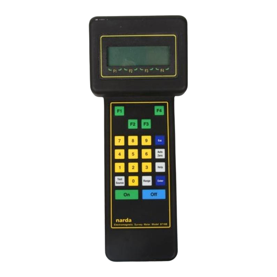
- Page 8 Keyboard The Model 8718 has four groups of keys distinguished by their color. Function keys (green) Numeric keys (yellow) Special Function keys (white) Power keys (blue, green) Power Keys Two power keys are used to turn the Model 8718 On and Off.
- Page 9 Numeric Keypad Use the numeric keypad to enter number data into the Model 8718. You also use the numeric keypad to select an option listed on the display screen. Special Function Keys Six special function keys enable you to perform specific functions.
-
Page 11: Getting Ready
Getting Ready Introduction This section will help you get ready to take measurements with your Model 8718. Information is included for selecting a probe, connecting the probe to your Model 8718, and connecting the optional fiber optic link. Probe Selection If you have more than one Series 8700 probe, select the probe best suited for your task. -
Page 12: Connecting A Probe
Connecting a Probe Connect the cable of your probe to the probe connector at the top of your Model 8718. Make certain that the retaining ring of the connector is securely fastened. Using a Fiber Optic Link (optional) A fiber optic link is useful when remote or low frequency (<30 MHz) readings are to be made with your Model 8718. -
Page 13: Making A Measurement
Introduction This section will help you take measurements with your Model 8718. Information is included for turning the meter on, selecting, zeroing, and testing a probe, plus an explanation of the main measurement screen of the meter. Some general information is also included about measurement surveys, precautions you should observe, and the use of probe correction factors. - Page 14 Narda's 8700 Series system is completely modular — all 8700 meters work with all 8700 probes. The single most important thing you must do is "tell" the 8718 meter which probe you are using. The Model 8718 has the basic characteristics of every 8700 Series probe stored in its internal memory.
- Page 15 To select from the PROBES IN MEMORY... 1. If you haven’t already, press F1 (MEASURE). 2. The model number and the serial number of the last probe used will be displayed on the second line of the display. If you want to use the same probe, press Enter.
- Page 16 To use a PROBE that is NOT IN MEMORY... If you haven't already, press F1 (MEASURE). The model number of the last probe used will be displayed on the second line of the display. If you want to use the same model probe, press Enter. S E L E C T P R O B E M O D E L...
- Page 17 A 8 7 2 2 D S N X X X X X 3 0 0 - 5 0 G H z E - F L D 3 0 0 S T D S H A P E D Y E S M E N U Zeroing the Probe The probe and meter must be “zeroed”...
- Page 18 • The field strength is not low enough. Move away from the antenna and use the storage case to zero the probe. • The probe is damaged. Try another probe. To reconfirm the zero while the instrument is in use... Establish a zero density environment for the probe as before.
- Page 19 (see Alternate Display Screen). If parameters for the you have entered a frequency, you Model 8718 will switch to the Alternate Display Screen. You will also reset the maximum value at the same time. If you have not entered a frequency...
- Page 20 Alternate Display Screen The Alternate Display Screen is very similar to the Main Measurement Display Screen with one difference. On the third line an instantaneous indication of the percent of standard is shown instead of displaying a maximum value. This screen should only be used with flat response probes for single frequency measurements or where all the emitter frequencies are close and the standard has the same limits.
- Page 21 value to the standard at the frequency shown on line 3. This instantaneous readout of percent of standard is particularly useful where the allowable level must normally be calculated. If you are using a probe in memory or have entered a numeric correction factor, the meter will also be correcting for probe frequency deviation.
- Page 22 Using Audio Alarms You can set an audio alarm to sound at a specific value. You can also activate a variable tone alarm. Both alarms can help you conduct surveys and can provide a warning of high electromagnetic fields. You can even use both at the same time. Under these conditions, the variable tone alarm will change with the field strength unless the threshold you specified is exceeded.
- Page 23 Testing the Probe Your Model 8718 is equipped with two RF sources for testing probes. Press Test Source and both sources will stay on for approximately 20 seconds. A contact on the right side of the unit is used for testing low frequency probes.
- Page 24 Correction factors can be used: • When there is only a single emitter being surveyed. • When there are multiple emitters all operating at the same frequency (this is often the case with industrial equipment). • When there are multiple emitters with frequencies that are close to each other and the nearest calibration frequencies have very similar correction factors.
- Page 25 To use a correction factor for a probe NOT in memory... Press F2 (MENU). The First Menu Screen will appear. Press 3 (COR FACT). A screen will appear that shows the correction factor. Use the correction factors on the handle of the probe to determine the appropriate correction factor and then use the numeric keys on the meter to enter this value.
- Page 26 The ellipse ratio is the ratio of readings that occur when one rotates the probe around the axis of its handle. Narda calibrates its probes by rotating the probe about its axis and using the mean value to determine the correction factor.
- Page 27 Obtaining a Reading A reading is obtained by holding your Model 8718 in one hand and your probe in the other. As you approach the source, observe the bar graph and measured value of signal strength on your meter. If you know where the source of energy is, point the probe towards it.
- Page 28 Precautions When making measurements of electromagnetic fields, a potential exists to expose yourself to excessive levels. Approach the source of energy slowly and begin making measurements from a distance at which low field levels exist. Be prepared to evacuate the area immediately if RF field levels in excess of the applicable standard are observed.
-
Page 29: Menu System
Using the Menu System Introduction This section will help you use the Model 8718's menu system. The menu system allows you to enter and store data and to select various options during operation. The menu system is always available from any measurement mode. - Page 30 First Menu Screen 1=SETUPS 5=PROBE 2=DISPLAY AV 6=UNITS 3=CORR FACT 7=AUDIO 4=BAT TEST 8=NEXT Menu Options Up to four sets of measurement situations can be stored and recalled. Setups are similar to macros in other computer SETUPS programs and can save keystrokes when repeating measurements with the same meter settings.
- Page 31 Second Menu Screen 1=CABLE/FO 5=RS232 2=TIME AVG 6=STDS 3=DATA LOG 7=BACK 4=TIME SET 8=NEXT Menu Options Select between the standard probe cable CABLE/FO input and the fiber optic receiver. Turn fixed time averaging (various duration) on or off. TIME AVG Turn the spatial averaging mode (used for whole body averaging measurements) on or off.
- Page 32 Third Menu Screen 1=LOCKOUT 3=BACK 2=BLANKOUT The three menu items provide these options: Menu Options Lock the keypad so that settings will not LOCKOUT accidentally change. To release, press ENTER and ESC together. Blank the display and lock the keypad. To BLANKOUT release, press ENTER and ESC together and then select another menu item.
-
Page 33: Index
Computer Operation ........7 Connection ...........6, 12 COR FACT, menu ........30 Correction Factors........23 Correction Factors, Probe ......24 Entering Model .........14 DATA LOG, menu........31 Selection ...........11 Description, 8718 ..........3 Test Sources ..........6 DISPLAY AVG, menu .........30 Testing ............23 Display Screen Alternate ...........20 Zeroing............17 Main............19 PROBE, menu ..........30... - Page 34 Safety Test Solutions communications company USA: 435 Moreland Road Hauppauge, NY 11788 Tel 1-631 231-1700 Fax 1-631 231-1711 E-Mail NardaSTS@L-3COM.com www.narda-sts.com GERMANY: Sandwiesenstrasse 7 D-72793 Pfullingen Tel +49-7121-9732-777 Fax +49-7121-9732-790 E-Mail support@narda-sts.de www.narda-sts.de...
Need help?
Do you have a question about the 8718 and is the answer not in the manual?
Questions and answers