Table of Contents
Advertisement
Quick Links
http://www.narda-sts.it
User's Manual
SERIAL NUMBER OF THE INSTRUMENT
You can find the serial number
side of the receiver unit baseplate and on the side of the Power Pack.
Serial number is in the form: 000XY00000.
The first three digits and the two letters are the Serial Number prefix, the last five
digits are the Serial Number suffix. The prefix is the same for identical instruments,
it changes only when a configuration change is made to the instrument.
The suffix is different for each instrument.
Document AMS8061EN-81008-1.22 – Copyright © NARDA 2018
Sales & Support:
NARDA
Via Leonardo da Vinci, 21/23
Safety
20090 Segrate (MI) -
Test
Tel.: +39 02 2699871
Solutions
Fax: +39 02 26998700
S.r.l. Socio Unico
AMS-8061
AREA MONITOR SELECTIVE
Manufacturing Plant:
Via Benessea, 29/B
17035 Cisano sul Neva (SV)
ITALY
Tel.: +39 0182 58641
Fax: +39 0182 586400
on the upper cover of the receiver unit, on the
Advertisement
Table of Contents

Related Manuals for NARDA AMS-8061


Summary of Contents for NARDA AMS-8061
- Page 1 Serial Number suffix. The prefix is the same for identical instruments, it changes only when a configuration change is made to the instrument. The suffix is different for each instrument. Document AMS8061EN-81008-1.22 – Copyright © NARDA 2018...
- Page 2 NOTE: ® Names and Logo are registered trademarks of Narda Safety Test Solutions GmbH and L3 Communications Holdings, Inc. – Trade names are trademarks of the owners. If the instrument is used in any other way than as described in this User’s Manual, it may become unsafe.
- Page 3 1 General information Page 1.1 Documentation.............. 1.2 Introduction........…………………….. 1.3 Standard accessories..........1.4 Main specifications......…...... 1.5 Max acquisition time…………………………………….. 1.6 AMS-8061 receiver panel …………..….…………….. 2 Installation and use Page 2.1 Introduction............…... 2.2 Initial inspection.............…... 2.3 Working environment..........…..… 2.4 Return for repairs...........…...
- Page 4 4.6 FTP Connection Data……………………………………… 4-21 5 Packaging Instructions Page 5.1 Introduction………………………..…………………..…..5.2 Packaging Instructions…………......…..… 6 Action of the wind on the AMS-8061 Page 6.1 Introduction………………………..…………………..…..6.2 AMS-8061……………………......…..…… 7 Instructions for use of the 8060-SW02 control software Page 7.1 Introduction…………...........…..7.2 Hardware requirements..........…..
- Page 5 7-75 7.6.11 First installation and parameter setting……………………… 7-75 7.6.12 FTP-GPRS commands………………………………………… 7-96 7.6.13 Additional tests and hints……………………………………… 7-96 7.6.14 AMS-8061 Firmware updates…………………………………. 7-97 7.6.15 Data download calculation and space occupied in the FTP server……………………………………………………………………. 7-97 7.7 Uninstalling software……………………………………………… 7-98 Contents...
- Page 6 8 Data presentation Page 8.1 Introduction..….......……..... 8.2 The Calendar..........…....8.3 Data window..........…..….. 8.4 Main commands........…..…..……..8.4.1 File…………………………………………………...…... 8.4.2 Option…………………………………………...……….. 8.4.3 Trace……………………………………………………. 8.4.4 Marker……………………………………………..…….. 8.4.5 Vertical…………………………..………………..……. 8.5 Secondary commands……..………………………..…… 8.5.1 Save Files……………………………………………..8.5.1.1 Save File in ASCII format…………………………..8.5.2 Open Files……………………………………………….. 8-10 8.5.2.1 Open Autotext file……………………………………..
-
Page 7: Table Of Contents
Figure Page AMS-8061 Field Monitoring System……………………. EHA-2B-01 Antenna……..………………………………… AMS-8061 receiver unit panel……………………………. AMS-8061 Receiver unit panel…………………………… AMS-8061 Field Monitoring System ..…………………… DB9 Female front side view………………………………. 2-16 Slot for the SIM card………………………….……………. 2-17 Slot for the Micro SD card…………………………………. 2-18 AMS-8061 Field Monitoring System…………………….. - Page 8 • Ground connections must not be interrupted intentionally; • To prevent the possible danger of electrocution, do not remove any covers, panels or guards installed on the device, and refer only to NARDA Service Centers if maintenance should be necessary;...
- Page 9 Descrizione STAZIONE DI MONITORAGGIO SELETTIVA Description AREA MONITOR SELECTIVE Modello AMS-8061 Model è conforme ai requisiti essenziali delle seguenti Direttive: conforms with the essential requirements of the following Directives: Bassa Tensione 2014/35/EU Low Voltage Compatibiltà...
- Page 10 This page has been left blank intentionally EC Conformity...
-
Page 11: Ams-8061 Field Monitoring System
1.1 Documentation This Users Manual contains the following annexes: • A form to return to NARDA with the device when requesting service. • A checklist of the parts included in the shipment. This Users Manual also includes the description of the accessories of the system for distributed frequency selective monitoring of environmental electromagnetic fields. - Page 12 1.3 Standard accessories The monitoring station is composed by a main measuring/processing unit, GSM modem with GPS module and antenna system. An RF transparent radome protects the station from the weather. The measuring unit comes ready to be mounted on its pole and connected to the power pack. The standard solar panel has to be mounted on the support base.
-
Page 13: Technical Specifications Of Ams-8061
Tables 1-1 – 1-2 list the specifications of AMS-8061. 1.4 Main Specifications TABLE 1-1 Technical Specifications of AMS-8061 Frequency range 100 kHz – 6 GHz (in accordance with antenna specifications) User-Programmable frequency bands Up to 20, individual start-stop frequency settings... - Page 14 Communication FTP and CSD protocols via internal GSM/GPRS modem, Ethernet, RS-232 and USB link. Data download FTP: automatic to server; CSD: automatic or manual to PC SIM card type (not included) Enabled for selected data transmission SMS to 10 mobile phones (daily report of max. EMF value, battery voltage) Battery management Every record includes Battery Voltage and Charge Current value Temperature and humidity sensors...
-
Page 15: Settings/Queries Of The Ams-8061
Settings can be made and the devices can be queried via SMS, serial connection, Ethernet, GSM or line modem, FTP communication through FTP server. The following table describes the different possibilities. TABLE 1-2 Settings/Queries of the AMS-8061 Possible functions 8061 via Modem... -
Page 16: Eha-2B-01 Antenna
The AMS-8061 system is equipped with mod. EHA-2B-01 antenna. Fig. 1-2 EHA-2B-01 Antenna The EHA-2B-01 triaxial antenna includes a triaxial magnetic field sensor. Computation of electric field, expressed in V/m by the station, is done assuming the measurement is taken in far field condition where the known ratio between magnetic and electric field allows good correlation accuracy. -
Page 17: Ams-8061 Receiver Unit Panel
1.6 AMS-8061 receiver panel Fig. 1-4 AMS-8061 receiver unit panel Legend: 1) GSM antenna 2) SIM card slot 3) GPS antenna 4A) Status LEDs 4B) Controller LEDs 5) RS232 serial interface connector 6) Power switch 7) Power supply connector 8) RF input N connector... - Page 18 This page has been left blank intentionally General Information...
- Page 19 Any part of the instrument – with the sole exception of the air filters (see 2.4 Return for repairs Service chapter) - can only be replaced by NARDA, therefore, in case of damage to parts and/or malfunctions, contact the NARDA service center.
-
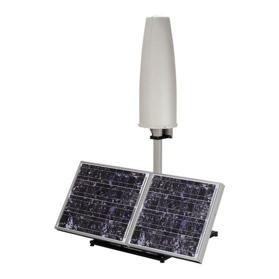
Page 20: Ams-8061 Field Monitoring System
It is suggested to replace air filter at least once a year or more frequently if needed. The AMS-8061 Field Monitoring System consist of a vertical housing with 2.6 Installation circular shape made of material that is transparent to electromagnetic and use fields. - Page 21 The AMS-8061 Field Monitor is designed to operate outdoors, in the 2.6.1 Installation vicinity of the electromagnetic fields sources that shall be controlled, and under the most severe environmental conditions. 2.6.1.1 Support base, Install the Support base on the site to be monitored...
- Page 22 Remove the bolt from the pole support, place the pole and fasten it to the base using the bolt with nut and washers. Using the supplied pole, whose characteristics have been carefully assessed, is recommended to avoid any alteration of the field to be monitored.
- Page 23 2.6.1.2 Solar panel 2.6.1.2.1 Solar panel The accessories included are: 1) 40W Solar panel (2 pcs); mounting kit 2) Hexagon head bolt M4x10mm (4 pcs.); 3) Upper L shaped bracket (1 pc.); 4) Tooth washer Ø4mm (4 pcs.); 5) M4 nut (4 pcs.); 6) M5 nut (2 pcs.);...
- Page 24 2.6.1.2.2 Installation Steps Upper L shaped bracket S shaped bracket and PA6 black bracket 55deg lower support Installation and use...
- Page 25 Installation and use...
- Page 26 2.6.1.3 Install the Solar Unscrew the inside the without losing it Pan head screw PA6 black bracket panel to the completely. Support base Insert and slide the Solar panel into the fiberglass pole and position the 55deg lower support on the base Position the Solar panel and the Support base on the ground as shown and install the 55deg lower support.
- Page 27 Position the Solar panel and the Support base on the ground as shown below. In the northern (boreal) hemisphere, the AMS-8061 should be installed with the solar cells facing south, in order to take the best advantage of the solar radiation for continuous recharging of the internal batteries.
- Page 28 To ensure maximum efficiency of recharging and optimum autonomy of the internal batteries, it is a good rule to keep the solar cells of the AMS-8061 clean, inspecting them periodically. If necessary, clean them with a soft cloth and a normal glass cleanser.
- Page 29 Remove the Power Pack cover 2.6.1.4 Solar panel wiring and fuse Remove the nut from the chock of the solar panel cable. Installation and use 2-11...
- Page 30 Thread the cable through the hole in the box and screw the nut to fasten the chock to the Power Pack. Place the fuse. Plug the solar panel connector. Close the Power Pack box. 2-12 Installation and use...
- Page 31 Before mounting the receiver unit on the pole, unscrew the 2.6.1.5 Receiver unit Pan head screw inside the both without losing it completely. mounting PA6 black brackets Mount the receiver unit on the pole. Fasten the unit by tightening the bracket screws Installation and use 2-13...
- Page 32 Remove the nut from the chock of the power cable. Install the power cable by mounting the chock in the hole of the receiver baseplate; plug the power supply connector to the receiver unit holding by the plastic part. 2-14 Installation and use...
- Page 33 Do not insert or remove the antenna holding it by the head or by the data cable as serious damage may occur. The AMS-8061 station cannot operate without antenna even when downloading acquired field data. In case the antenna is accidentally removed when station is ON a reset will be required: switch the station OFF, connect the triaxial antenna and switch ON again.
-
Page 34: Db9 Female Front Side View
2.6.1.7 Connectors The AMS-8061 has an USB, Ethernet and RS-232 port for direct connection to Personal Computer. • USB connector for direct connection to Personal Computer. • Ethernet connector and its led for direct connection to Personal Computer. TABLE 2-1 Led Ethernet status... -
Page 35: Slot For The Sim Card
AMS-8061. If you use a rechargeable SIM Card, make sure it is charged. Before using the SIM Card with the AMS-8061, disable the PIN code using the proper function available on any mobile phone. The SIM card adopted shall be enabled to data transmission. -
Page 36: Slot For The Micro Sd Card
1 minute. However, the AMS-8061 supports Micro SD Cards. It is solely intended for backing up data when no other way is accessible among the many present (RS232, USB, FTP, Ethernet and MODEM-CSD). -
Page 37: Led Micro Sd Card Status
The Led let the user know about the state of process as shown in the following table. TABLE 2-3 Led Micro SD card status LEDs Status Action Blinking RED DATA is being storing *** DO NOT REMOVE the SD Card *** Steady RED SD Card ERROR This can be caused by:... - Page 38 2.6.1.11 Led ON When the monitoring station is switched on, the Led ON is first lit with a in relation to the steady light for about 5 seconds, then starts to blink at the rate of one blink per second, indicating that the monitoring station is active in normal Stand- status of the By conditions and not in the low consumption mode.
- Page 39 Considering that it has been designed for outdoor use and the main operations are generally performed remotely by means of an internal GSM modem, the AMS-8061 does not have any control or connection on the outside of the protective case.
- Page 40 2.6.1.14 Bags The AMS-8061 is usually installed outdoors where atmospheric agents, especially strong winds, can endanger its stability. To ensure the necessary stability under the worst possible conditions, the unit is supplied with three ballast bags that can be filled with water or sand and fastened to the base of the mast.
- Page 41 A complete battery charging should be completed (48 hours) before 2.6.2 Battery charging starting measurements. Remove the Power Pack cover. Disconnect the solar panel from the Power Pack removing the chock. Connect the provided power supply/battery charger for a complete charge. Installation and use 2-23...
- Page 42 Plug the battery charger with the proper adapter to the mains outlet before connect the multipole connector to the Power pack. Fasten the cable to the strain relief. Thread the cable through the hole in the box and screw the nut to fasten the chock to the Power Pack.
- Page 43 Execute the following wiring in the case an external power supply is 2.6.3 External power requested during measurements. supply Remove the Power Pack cover. Disconnect the solar panel from the Power Pack removing the chock. Connect the provided power supply/battery charger. Installation and use 2-25...
- Page 44 Plug the battery charger with the proper adapter to the mains outlet before connect the multipole connector to the Power pack. Fasten the cable to the strain relief. Thread the cable through the hole in the box and screw the nut to fasten the chock to the Power Pack.
- Page 45 GSM is switched on directly by the AMS-8061 either to make a call or to send an SMS (depending on the settings) to the modem number(s) memorized. Afterwards, the GSM remains on stand-by for 15 minutes.
- Page 46 The selective unit is OFF every time the battery voltage is lower than 11 V. Switching ON/OFF 2.12 RF signals of The antenna used in the AMS-8061 and the receiver input stage contain highly sensitive elements. dangerous intensity Never place the unit in an electrical field higher than the maximum allowed level.
- Page 47 “Fax Printer” will restore the normal operation. To get a fast response from NARDA support center it is very important to provide always a picture reporting the system setup (storing settings, alarms status, start and stop of the download, etc..) to give a correct description of the conditions under which the area monitor was working during the faulty of the unit.
- Page 48 This page has been left blank intentionally 2-30 Installation and use...
- Page 49 Although the AMS-8061 can operate in both modes, MODEM and GPRS, it cannot do it at the same time. This means that a setting command is used to configure the AMS-8061 to work either via MODEM way or via GPRS. Document AMS8061EN-81008 -1.22 - © NARDA 2018...
- Page 50 Here, an example of directory structure: FTP_Root 000WE80201 8061.CFG 8061.set 8061FLD.TXT 17_08_01_07_09_.D61 000WE80202 8061.CFG 8061.set 8061FLD.TXT 20_00_01_07_09_.D61 The User must ensure that the directory is already present on the FTP root as the AMS-8061 will not create it. GPRS and FTP...
- Page 51 Whenever the AMS-8061 connects to GPRS and accesses to FTP, it looks 3.3 Configuration (read) for a file named 8061.CFG in its directory (its serial number). If the file is present, the AMS-8061 retrieves it and calculates the checksum in order to use it and thus get the new configuration.
- Page 52 of hour. GPRS Unsigned char This parameter represents the interval between GPRS Interval connections (starting from the first connection which is done at Appoint). It is expressed in hours. Prxon Unsigned char This is the flag for connecting to GPRS upon alarms. If bit 0x01 is ‘1’...
- Page 53 19 bands follow here exactly as the above described band 1. n= 1 to 19 n*10+78 StartFreq float Little Endian 32bit IEEE floating point number representing the start frequency of the n band and it is expressed in Hz. n*10+82 StopFreq float Little Endian 32bit IEEE floating point number...
- Page 54 “---“ (up to now option), in order to avoid huge files and long transfer time, the number of records will be limited to 5000. Once the AMS-8061 has read the file 8061FLD.TXT, it deletes it. It will be replaced later with the newer self created 8061FLD.TXT which reflects the last record.
- Page 55 After having read the FLD file, which informs the AMS-8061 about which 3.5 Record File (Write) records have to be uploaded, it writes a file named HH_mm_GG_MM_YY.D61 where: • HH is hour of the day. • mm is minute of the day.
- Page 56 3.8 Setting Status. (Write) After having written the EVENT.TXT file, the AMS-8061 writes a file named 8061.set which reflects the configuration of the monitoring station. Similarly to the Configuration 8061.CFG the file is binary. This file is solely intended for reading as it is ignored by AMS8061 and therefore any change of it will be discarded.
- Page 57 GPRS Unsigned char This parameter represents the time the GSM remains ON after a GPRS connections. It is expressed in quarter of hour. GPRS Unsigned char This parameter represents the interval between GPRS Interval connections (starting from the first connection which is done at Appoint).
- Page 58 StopFreq float Little Endian 32bit IEEE floating point number representing the Stop frequency of the first band and it is expressed in Hz. Reserved Unsigned char Reserved, it must be 0 Reserved Unsigned char Reserved 19 bands follow here exactly as the above described band 1. n= 1 to 19 n*10+78 StartFreq...
- Page 59 It is ten times the last measured temperature. Thus, in order to get actual temperature Temp should be divided by 10 This parameter shows the AMS-8061 Relative Humidity. It is ten times the last measured Relative Humidity. Thus, in order to get actual Relative Humidity, RH should...
- Page 60 3.9 GPRS – FTP Settings In order to establish a GPRS connection and a FTP transfer, a number of data are required which are divided into 2 main fields as follows. Each fields cannot be more than 31 characters. These commands cannot be executed via FTP/GPRS (because they would need to be already correctly set).
- Page 61 This command sets the internal real clock time by using the #SMSSTS Set Timedate SMS provider’s information. nnnnnnnn* where To use it id (the AMS-8061 telephone number) must be sent. nnnnnnnn is the This command works assumes that the SMS provider gives telephone number of AMS-8061 the correct Clock/Date and its feedback is within 30 seconds.
- Page 62 The checksum is intended for verifying the reliability of the array read mainly from the AMS-8061’s side as a corrupt configuration could potentially make the AMS-8061 ineffectual. Therefore the application must ensure that the checksum in the 8061.CFG file reflects the actual state of the configuration setting.
- Page 63 This paragraph describes the structure of a multiband record. 3.11 D61 Structure, These records are created by either GPRS/ftp enabled (files D61) or Download “?FLS” command. description 3.11.1 Command Mode Sintax Description ?FLS HH:mm,dd/MM;n Request for n samples starting from Hour HH and minute mm of the day dd of the month MM of the current year.
- Page 64 3.11.3 Selective Multiband Structure description Header Reserved Reserved Reserved Charge Byte 1 Byte 2 Byte 3 Byte 4 Byte 5 Byte 6 Byte 7 Byte 8 Battery Temperature Alarm PERTS PROC Month DateTime Byte 9 Byte 10 Byte 11 Byte 12 Byte 13 Byte 14 Byte 15...
- Page 65 Byte 9 (Voltage) It is the voltage of the AMS-8061 battery. The number should be considered as an unsigned 8 bit integer. To get the correct value of the battery voltage the following formula is used: Volt = Voltage * 0.133...
- Page 66 The figure named Temperature is shown as follows: 7 bit unsigned integer Temperature FLAG Byte 10 (Temperature) It is the Temperature recorded in the interval. The number should be considered as an unsigned 7 bit integer. In order to avoid negative figure an offset of 40 degrees centigrade is added thus, to get the correct value of the temperature, the following formula is used: T Centigrade = Temp - 40.
- Page 67 The figure named PROC is shown as follows: Reserved Reserved AVGP AVGPeriod MISC 4 bit unsigned integer Byte 13 This figure ( PROC ) reports how the process took place in the period. • RMS (D05) flags whether the averaging has been made linear mean (AVG) or Root Mean Square(RMS).
- Page 68 3.11.4 GPS Information The 16 bit figure named Latitude int is shown as follows: D15 D14 D13 D12 D11 D10 D9 Byte Degree Minute 17/18 The figure named Latitude int is made of 4 fields and represents the integer part of the GPS Latitude. •...
- Page 69 The 16 bit figure named Longitude Fract is shown as follows: D15 D14 D13 D12 D11 D10 D9 D8 D7 Byte Ten thousandths of a minute 23/24 The figure named Longitude Fract is a little-endian unsigned 16 bit integer and indicates the fractionary part of the GPS Longitude and it is expressed in Ten-thousandths of a minute.
- Page 70 Reserved D15 D14 D13 D12 D11 D10 D9 D8 D7 Byte 31/32 Then 16 bytes follow and contain all data related to the first band Freq_Start Freq_Stop Peak Reserved +2 +3 The, additional packets of 16 bytes follows according to[NOB] 3-22 GPRS and FTP...
- Page 71 3.11.5 Band Packet description The figure named Freq_Start is shown as follows: Freq_Start Byte +0 - +3 32 bit Float Freq_Start is a Little Endian 32bit IEEE floating point number representing the start frequency of the band and it is expressed in Hz If Freq_Start=0xffffffff or Freq_Start=0x00000000 then the band is empty and should be ignored.
- Page 72 The number should be considered as a Little-endian unsigned 16 bit integer multiplied by the Scaler above calculated. In the particular case in which the figure Avg is equal to 0xFFFF then Avg value must be considered invalid (AMS-8061 was not able to get a measurement) and the data are meaningless.
- Page 73 As the monitor station, when sending data, suspends all other tasks ( sending data gets highest priority) storing included, it is preferable asking not many data at once so that the AMS-8061 is not engaged, for say, for more than 10 seconds. Therefore, when having a lot of data to retrieve, it is better to split up into consecutive smaller requests instead of asking the whole block so that the AMS-8061 can service its own tasks in between them.
- Page 74 This page has been left blank intentionally 3-26 GPRS and FTP...
- Page 75 4.1 Introduction This Chapter includes a list of commands which can be sent to the AMS-8061 in the form of SMS, by means of a mobile phone, or directly by serial connection (RS-232 cable or modem), USB and Ethernet. Because of their text length, some commands cannot be used via SMS, such as: ?EVN, ?EVNL, ?EVNR, ?BNDALL.
- Page 76 4.2 Command list Query COMMANDs Syntax Function #SM?ALR* Field Alarm threshold query command. Current Acquisition mode query command (Alias ?AQP) #SM?AQ_* Alias of ?AQ_ command #SM?AQP* #SM?BAT* Battery voltage query command. #SM?BNDn* Specified Band data query command. #SM?BNDALL* All Bands data query command Station internal clock query command.
- Page 77 Setting COMMANDs Syntax Function #SMSALR(parameters)* Alarm threshold setting. #SMSAQ_(parameters)* Acquisition mode setting (alias #SMSAQP) Alias for SAQ_ command #SMSAQP(parameters)* Hang off current call. #SMSATH* #SMSATH0* Hang off current call and switches the Modem off. #SMSAVGx* Average Time for Alarm and Warning Bands Frequency setting #SMSBND(parameters)* Clock date setting.
- Page 78 GPRS Connection Data Syntax Function #SMSGPR0<apn>* Access Point Name setting. #SMSGPR1<gun>* User Name setting Password setting #SMSGPR2<gpsw>* Username and Password must only contain alphanumeric characters; any special characters are not allowed. FTP Connection Data Syntax Function #SMSGPR3<fun>* User Name setting. #SMSGPR4<fpsw>* Password setting IP Address setting...
- Page 79 Query commands interrogate the station for data; it responds back with a 4.3 Query COMMANDs message containing the requested information. Query commands contain a ? character in the command string. Command Description Example ?ALR Field Alarm threshold query command. Example: #SM?ALR* The answer displays the threshold value in Response: ALR=20 V/m;...
- Page 80 Command Description Example Request the SIM card PIN’s status. Example: #SM?CPIN* ?CPIN The response in the format #SM +CPIN: SIM <s>* Where <s> can be either Response: - READY: contains the last string obtained by the #SM +CPIN: SIM READY* “AT+CPIN?”...
- Page 81 R.rr is the release and MM/YY the date of the Where: internal firmware. democisano is the Station identifier Serial Number is written in factory. Nsts is the narda brand Date of calibration is the last calibration date, as AMS-8061 is the model dd.MM.YY. A.46 is the fw release and...
- Page 82 Command Description Example Request Modem status Example #SM ?MDM* ?MDM The response in the format #SM MDM=x*, Where <x> can be either: Response: #SM MDM=0* - 0: modem or Wifi OFF - 1: modem or Wi-Fi in activation process Another response: - 5: modem 2G is actived (may not be #SM MDM=6* connected to the network but it works and...
- Page 83 Command Description Example It asks for max recorded field, with date ?RPT Example: #SM?RPT* and time stamp since last automatic Response: RPT= Report was sent, and current battery MAX:2.14V/m voltage. (the “Send Report” function should 10:57 19/10/07 be enabled sending the “SENR” message). Battery=11.62V Showed field value is related to the Total band.
- Page 84 Command Description Example Modem phone directory list query Example: #SM?TDM* ?TDM command. Response: TDM= The answer displays the phone numbers 0123456789 stored in the modem phone directory or void VOID if empty in the format: void (a <LF> Line Feed after each number): void TDM= void...
- Page 85 Command Description Example Internal temperature and Relative Humidity ?TMP Example: #SM?TMP* query command. Response: TMP=39.08,30.4 It returns the internal temperature in °C Which means that the internal and the RH % in the format: Temperature is 39.08°C and the RH is TMP=TT,RH.
- Page 86 Command Description Example SMS programming time setting query Example: #SM?TSS* ?TSS command. Response: Answer returns information (as set by the TSS=ON 17:26 ( 1q) each 24h STSS command) with the following format: It means that the modem is scheduled TSS=ON|OFF HH:mm ( Xq) each YYh to be switched on at 17:26 and remain (DIS) on for 1/4 of hour, and it happens every...
- Page 87 Setting commands send setting data to the system, the station can answer 4.4 Setting COMMANDs back with a message with requested information or a setting confirmation. Setting commands contain a “S” character at the beginning of the string. Command Description Example Alarm threshold setting.
- Page 88 Command Description Example Specified band frequency setting Example: #SMSBND 1,21,80* SBND n, Format: SBND n,start,stop Response: BND=OK start,stop Where: n is the band index, between 1 and 20 The first band (#1) is set starting at 21 Start and Stop are the corresponding MHz and ending at 80 MHz frequencies, expressed in MHz.
- Page 89 Command Description Example This command disables the Ethernet port SDIE Example: #SMSDIE* planned activity. Response: If disabled, the LAN port stays permanently TSE=OFF 12:00 each 24h off independently from the time schedule confirming the LAN port is disabled set via the STSE command. (OFF).
- Page 90 Command Description Example SMS Report send enabling. Example: #SMSENR* SENR When enabled the station power on the Response: GSM, at the time set with the STSS TSS=ON 12:00 ( 2q) each 24h command, initializes communication and Confirm the station is enabled to send send the report with a SMS message to all SMS report.
- Page 91 Command Description Example Alarm mask setting. Example: SMSK The mask contains mnemonic symbols #SMSMSK AL S* enables field and representing each alarm as in the following case open alarms to be notified by table. Symbols can be in each order. SMS.
- Page 92 Command Description Example Reset to both default configuration and Example: #SMSRSTR* SRSTR storing rate. Response: RST RATE=OK Similar to SRST command, in addition to confirming the command has been its default settings, resets also the storing granted. rate to 6 minutes. Pay attention this command invalidates any data already stored in the Station.
- Page 93 Command Description Example STSM Modem programmed time setting. Example: #SMSTSM 14.53.01.24* In the following format: Response: #SMSTSM HH.mm.xx.ee* TSM=OFF 14:53 ( 1q) each 24h where: HH.mm is the MODEM power on the modem will power on at 14:53, will time (switched on and in Stand-By). stay on for ¼...
- Page 94 4.5 GPRS Connection The following commands and information are related to the adoption of the Data GPRS and FTP protocol communication. In the proper chapter of this manual, it is specifically described the syntax, format and protocol for data and settings files. GPRS Connection Data Field Description...
- Page 95 4.6 FTP Connection Data The following commands are specific for FTP protocol communication. FTP Connection Data Field Description Setting command Command to be issued by either SMS or RS232 The User Name required for accessing to the FTP #SMSGPR3 <fun>* User Name for server.
- Page 96 This page has been left blank intentionally 4-22 SMS Messages and Commands...
- Page 97 This section provides the information useful for a correct packaging in case the unit has to be returned for service to the factory or whenever you need to prepare the AMS-8061 unit for shipment. The station should be disassembled stepping back the installation procedure included in section 2.
- Page 98 Box C inside view Box C contains power pack and box B Box F contains the receiver unit Packaging Instructions...
- Page 99 Box E contains antenna Box D contains box F and box E Box D inside view Packaging Instructions...
- Page 100 Box G contains radome Box H (main box) Packaging Instructions...
- Page 101 Insert Box C in the Box H Insert Box D in the Box H. Packaging Instructions...
- Page 102 Insert Box G in the Box H. Insert Box A in the Box H Packaging Instructions...
- Page 103 Box H ( Main ) Use pallet and straps for the final packing. Packaging Instructions...
- Page 104 This page has been left blank intentionally Packaging Instructions...
-
Page 105: Ams-8061 Field Monitoring System
This section provides the information necessary to install and use the Area 6.1 Introduction Monitor Selective AMS-8061 in the presence of wind. The Field Monitor is usually installed outdoors where the strong winds can endanger its stability that depends on the weight and eventual ballast bags or nylon wind strays. -
Page 106: Wind Resistance Of The Ams-8061
6.2 AMS-8061 Table 6-1 Wind resistance of the AMS-8061 Wind Wind Wind Overturning Stabilizing Weight Aerodynamic NOTE speed speed density pressure moment moment ballast form [km/h] [m/s] [N/mc] [N/m [Nm] [Nm] 3,60 1,00 1,20 1,25 0,75 0,32 0,49 -610,62 7,20... -
Page 107: Weight Ballast Variation In Comparison To The Wind
The weight of ballast bags filled with sand can be maximum 720 N; the maximum wind speed that does not cause the overturning of the AMS-8061 is 23 m/s (corresponding to about 83 km/h). The AMS-8061 must be firmly fasten by nylon wind strays for wind speed above 23 m/s. WIND... - Page 108 This page has been left blank intentionally Action of the wind on the AMS-8061...
- Page 109 The CSD section provides functionalities for the local RS232, USB and Ethernet communication too. The procedure for the correct use of the AMS-8061 system is the following: • Install the software on the PC that will be used to control the AMS- 8061 system;...
- Page 110 The software is based on the Windows operating system. The software features the following basic functions: • Querying and monitoring all the Field Monitors installed; • Programming different AMS-8061 Field Monitors individually with different acquisition modes; • Querying the Field Monitors at given times;...
- Page 111 The updated AMS-8061 firmware and software is available for downloading on the internet web site www.narda-sts.it or directly from the commercial offices of NARDA. The User should have administrator privileges to install and run the software in environments such as Windows Vista, 7, 8.
- Page 112 7.3 Installation of the 8061-SW02 control software shall be installed on the PC using the software Software Media supplied with the 8061 System. The installation procedure is as follows: • start the PC with the Windows operating system; • In Computer Resources, browse the Software Media supplied; •...
- Page 113 The installation can be aborted by clicking on Cancel. The installation folder must be specified. Click Next to confirm the default folder (recommended) or Change to modify. Click OK to confirm the directory. You can also type a different name; in Windows 7 the maximum number of characters for the name is 24 (including spaces);...
- Page 114 During the installation process the software will ask the User if he wants to cancel all the existing Passwords. If the answer is YES, all the stations and measurements already saved will be hidden, but still accessible by adding all the stations used and maintaining the original name (respecting upper and lower case letters) phone number.
- Page 115 The installation program needs certain system files to function properly. If these files already exist or are used by the system, it may happen the following message appears: In this case select Ignore and proceed with the installation in order to keep the files existing in the system.
- Page 116 7.4 Starting the program Click twice on the 8061-SW02 icon to start the software. First, a window appears displaying the software release, the presence and the status of the modem, the selected COM port. The first connection may take place either via GSM modem (if available, depending on station model) or via direct RS232 or USB connection.
- Page 117 7.4.1 Assigning After startup, the program normally searches the modem to be used to communicate with the Field Monitor on the first available COM port. the serial port If your modem (or serial cable in case of local connection) is connected to a different one, the COM port number must be assigned using the following procedure: •...
- Page 118 All AMS-8061 models can be connect to the PC via USB. installation When connecting the AMS-8061 to the PC USB port for the first time, a message informing that new hardware has been found will be shown. Enter in Peripheral management (Start > Control Panel > Device Manager).
- Page 119 7.4.2 Checking for the If there is any doubt about the presence of the modem or its working conditions, proceed as follows using the Windows commands (the modem procedure may differ slightly depending on the operating system used): • on the Start icon, access the system settings and select Control Panel;...
- Page 120 • The diagnostic section allows to test the modem: The serial port selected must correspond to the value of COMM=N on the Destination line of the icon properties of the software. In the example shown above, for the modem “Standard a 9600 bps” write COMM=2 (in capital letters).
- Page 121 Preferably, the modem should be connected to a direct phone line (the same connection used for a fax machine). Sometimes, if there is a switchboard system, it may only be possible to place outgoing calls but not to receive incoming calls (where an extension may be needed, etc.). Contact your switchboard operator for guidance.
- Page 122 The User must have administrator privileges to run the 8061SW-02 software in Windows 7; right click on the program .exe file and click on “Run as administrator” to temporarily run the program or application as an administrator until close it (Windows 7 also allows to mark an application so that it always runs with administrator rights).
- Page 123 In case a modem is detected, the message MODEM OK will appear. Instructions for use 7-15...
- Page 124 7.4.3 Entering the Before to access any software functions, the User is requested to enter a Terminal Terminal PASSWORD to prevent the improper use of the software by non PASSWORD admitted personnel. The screen looks like this: If the answer is YES, a window will be opened where it is possible to enter the Terminal PASSWORD for the management of the Field Monitors.
- Page 125 After entering the Password with OK, the software will request confirmation of the password before registering it into the system. The next screen will therefore look like this: At this point, type the same Password again. In case of any mistake, the software will display the following message: After the answer YES it is possible to re-enter the correct password;...
- Page 126 7.4.4 Changing a If it is necessary to change the Terminal Password, just press function key Password F10. The software displays the message: If the answer is YES, first enter the old Terminal Password, then enter the new one. If a wrong old Terminal Password is entered, the following message pops up: Press OK and try again.
- Page 127 7.4.5 Entering the After entering the Terminal Password needed to ensure the secure management of the Field Monitors (Station identifier, telephone number, Setting PASSWORD automatic downloads, automatic text file creation…), the software asks to enter a Setting PASSWORD which is needed to edit the parameter settings on the Field Monitors to be queried (alarm settings, storing rate, frequency bands, firmware upgrading…).
- Page 128 7.4.6 Main window After entering the Passwords, the program displays the main window: The communication between the remote station and the PC can be carried out in CSD and in FTP modes. 7-20 Instructions for use...
- Page 129 2. Remote communication in CSD mode is protected by a “Device Password” that is stored in every AMS-8061 Area Monitor. The same password must be set, by the user, in the CSD station list provided by the control software.
- Page 130 double click the first station listed in the FTP station list (new software installations show the “New8061FTP” station, on the list, as an example). The “Edit station” frame appears: click the button “GPRS Settings” 7-22 Instructions for use...
- Page 131 The GPRS Setting window allows to set stations for FTP or CSD click the “Read” button and type the Terminal password when requested. The “Read” buttons queries the station connected by RS232 or USB and displays, in the “Schedule” frame, which communication mode is enabled.
- Page 132 CALL to make a call to the station selected; • Hang up to end the call in progress; • Add Station to add a new AMS-8061 Field Monitoring station to the list; • Open Log File to show the Log of all the station activities •...
- Page 133 7.5.1 Alarm column The status of alarms relative to latest link, in the last column, is normally empty if there were no alarms. A red dot is displayed, followed by a description of the type of event causing the alarm in case of just one alarm. In case of no alarm, a green box with the word “None”...
- Page 134 7.5.2 Entering a new Before making calls or downloading data from an existing Field Monitor, station click the Add Station button to add the station to the list. The screen looks like this: The procedure to add a station is as follows: •...
- Page 135 7.5.3 Removing a station To remove a station from the list, click Remove Station. The message is: If the answer is YES, the software will ask for the Terminal Password and the station will be deleted; if the answer is NO, the operation will be aborted.
- Page 136 7.5.5 Automatic data The window for editing or adding the stations also provides an Automatic downloads Download function which makes monitoring fully automatic, with transfer of the data from the station, generation of the .TXT file, etc.. Therefore some stations can be programmed for manual connection, other units, after being called, will automatically transfer the data, while others again will automatically call the control PC at a preset time and download their data by themselves.
- Page 137 7.5.6 Answering By enabling the command PC Answering, every time the controller PC answers to an automatic call coming from the station, measured field data are downloaded automatically. The downloaded period starts from the first data after last download. To program the station for automatic calls, proceed as follows: •...
- Page 138 7.5.7 Calling When the PC Calling function is enabled, every time the station is called using the CALL or “Scheduled Call” commands, the data present on the station - and recorded since the latest download - will be automatically downloaded to the PC. This can be very useful because it makes unnecessary to remember the time of the latest download.
- Page 139 It will be saved in the AUTOFILE directory and placed at the same level of the txt file. The NARDA Area Monitor System can save a certain number of events in 7.5.9 Autoload Events the permanent memory of the station, so as to ensure traceability (independent from the operations of the control center) with regard to the settings and main activities of the station.
- Page 140 When exporting data, after the selection of the type of support, the data are automatically saved in a directory called 8059_EXP. Select Selective storing to enable the program to select which data to export, as shown in the figure below, otherwise all the data found will be exported.
- Page 141 7.5.11 Exporting data The Data Export function creates text files and, if enabled, .bmp files related to the time range specified by the user: After selecting the desired time range (From date – To date) click the Export button to create, in the AUTOFILE directory, the following text files: •...
- Page 142 7.5.12 Direct readings When the station is connected to the controller PC through the RS232 or USB cable, the Direct Readings button is used to open a window where it is possible to immediately read the basic station data. With this function the User can read the field values acquired by the station without post-processing them;...
- Page 143 7.5.13 Send settings The Post Settings key is used to open a window where settings can be defined for the selected station. This presetting operation allows to change the settings even if the station cannot be contacted at the specific moment, for any reason. All the settings are saved temporarily and sent to the station during the first link.
- Page 144 7.5.14 Calendar of The calendar, created automatically by the software, always shows the measurements current month and year and is used to select and display in graphical form the data downloaded from the selected Field Monitoring station, simply by clicking the button of the desired day or week. Only the buttons with blue characters contain data, which has been previously downloaded from the station.
- Page 145 Among the traces of the graph are also the ones showing the battery voltage and solar cells power balance. This information is extremely important and allows the user to program the maintenance of the batteries or the power supply system. Instructions for use 7-37...
- Page 146 7.5.15 Calling a station After the correct installation and configuration of the program 8061SW-02 via RS232 or USB as described in the paragraph "Software Installation" in this chapter, select the station to call and press the CALL button. The status bar will show: - The message “Checking MODEM”...
- Page 147 7.5.16 Calling a station To call an Area monitor, you should: Assign a station name or use an existing one (as described in the via GSM modem paragraph “Software Installation”) (CSD mode) Assign the SIM card telephone number (if the area monitor is located outside your country, please add the prefix of the country called and check your SIM card is enabled for international data calls) The modem shall be correctly configured and switched on...
- Page 148 Answering No, another window opens: If the answer is Yes, the software allows access to the station and then the data download takes place, with these data saved in the relative directory named 000WE50907. In this case the name saved in the station takes priority and the one in the list of the PC is updated.
- Page 149 7.5.17 Control window Once a link has been successfully established, in CSD mode or during local RS232, Ethernet or USB connection, the control window is opened for the selected station and it is possible to: • check the settings and parameters of the station; •...
- Page 150 7.5.17.1 Description of The control window is divided in different zones grouping the available controls commands by type and function. The main zones are: ALARMS divided in: • Last Field • WARNING • ALARM • Averaging Period • Battery Section •...
- Page 151 Get DATA divided in: • Start with the subcommands Since Last Time Date & Time The starting date must be not later than the Stop date. Starting date cannot be before “First Valid Date” displayed on the lower left side of the control window: The following message is displayed if trying to download data stored before the First Valid Date or an interval longer than memory capacity: •...
- Page 152 • Update Firmware to update the internal firmware of the station. Information about station firmware (rel. number and upload date) are displayed in the lower right side of the control window: • Station Date & Time with subcommand Set Clock, to transfer the current date of the PC to the station Synchronize on exiting, to make the above function (updating time and date at the end of every link) automatic.
- Page 153 7. When the external container is opened. Whenever an alarm occurs, the GSM modem will remain on for 30 minutes. It allows the AMS-8061 to send the proper SMS message and the operator to query the station and download the data.
- Page 154 7.5.17.4 Last Field The last field is the highest value of all averaged values set on rate chosen by the user, calculated on single bands. In practice is the highest average value. This field is refreshed each time you click the Last field button. This value can be remotely queried at any time from a mobile phone sending following...
- Page 155 7.5.17.6 Max Field Field alarm The field monitor features two thresholds of the field value readings, one for ALARM warning and one for alarm. Settings On exceeding one of these thresholds, a message is sent to the mobile phone or a call is done to the PC. This occurs only if the ON function is enabled in the NOTIFY ALARMs through window.
- Page 156 7.5.17.7 Battery Section Battery Alarm. The internal control system of the Field Monitor features a voltmeter for measurement of the battery voltage. This function ensures constant control of the power situation for correct operation of the system. Settings are made as for all the other alarms. The bar turns red when the battery voltage is below the factory preset threshold.
- Page 157 The RF components of the AMS-8061 are tested and calibrated individually after production. For best overall instrument accuracy the antenna factor is measured on the assembled AMS 8061, thus including all corrections of RF parts, if any. For this reason the certification date of the system and the last calibration date of the antenna are corresponding.
- Page 158 7.5.18 Schedule for Programming the station for modem links. MODEM To query the station by a remote PC linked to a line or GSM modem, the station modem must be on. In addition, when an alarm occurs, the station can automatically call the telephone number of the modem used by the control PC.
- Page 159 7.5.19 Schedule for SMS Querying the station with SMS messages. Similarly to the “Schedule for MODEM” frame, the “Schedule for SMS” offers the opportunity to define an additional time period during which the station modem will be ON (stand-by mode) and therefore able to receive CSD calls and SMS query and setting commands.
- Page 160 7.5.20 Rate Settings Configuration of data memorization. Data are saved in the station at a frequency (Rate) ranging from 1 to 15 minutes. Example: if the rate of 1 minute is selected, the station will store, every minute, the average value of all the measurements taken during the last minute.
- Page 161 Results acquired with the new setting will be displayed starting from the next day. If it is really necessary to change the settings, NARDA recommends one of the following procedure: •...
- Page 162 7.5.21 Get DATA Downloading data from the monitoring station to the PC. The data in the internal memory of the station can be downloaded after defining a Start and Stop event as follows: The Start and Stop of the data download is done between the following commands, in any combination.
- Page 163 GSM signal, some error messages may be received. In these cases, repeat the RECALL command. The AMS-8061 station cannot operate without antenna even when downloading acquired field data. In case the antenna is accidentally removed when station is ON a reset will be required: switch the station OFF, connect the triaxial antenna and switch ON again.
- Page 164 Many phenomena can affect good communications between the GSM errors modem of the AMS-8061 station and the modem of the PC. The selection of the port to which the modem is connected to, can generate a series of error messages.
- Page 165 The control of the checksum guarantees the quality of the data received. When this error occurs, sometimes the software closes the application and exits. No answer from the AMS-8061 station Message informing that data cannot be downloaded. Data cannot be downloaded.
- Page 166 If there are communications problems in CSD mode between the servers of different GSM Service Providers, the message LAST CALL DID NOT NEGOTIATE appears in the Status frame of the main window. The same message can appear when there is heavy traffic or when the server is unable to perform roaming.
- Page 167 7.5.23 Updating Update of internal Firmware It is important to update the station firmware in order to use all the new Firmware functions added and eliminate any bugs in the software. To update the firmware, use the Execute command. The monitoring station will place the old firmware in its memory and will try to load a new one.
- Page 168 In case, for any reason, the new firmware is not completely and successfully transferred AMS-8061, station will automatically restore the old firmware in order to prevent malfunctions or stops. The AMS-8061 firmware and software updates are available for downloading from the internet web site www.narda-sts.it 7-60 Instructions for use...
- Page 169 When the internal clock of the station is changed, some readings may no longer appear contiguous and gaps may be found. For this reason NARDA recommend to use of this function sparingly It is recommended to check the station clock before starting any new monitoring campaign.
- Page 170 Enable Setting Sub Bands Hang & Exit 7.5.26 Read Station Conf. To read the status of the AMS-8061 station, select Read Station Conf. Click on the button to start a new query of the station to update the control window.
- Page 171 7.5.30 Sub Bands The Sub Bands window allows viewing and setting up to 20 frequency bands to be investigated. When the tab is opened, the actual bands configuration is shown. Each band can be activated for the selective analysis by ticking the corresponding box.
- Page 172 Very high fields, which frequency is out of the overall frequency range of the created table (from minimum frequency of first band to the maximum frequency of the last one) but within the receiver range (100 kHz – 6 GHz) may cause saturation of the receiver causing wrong measurements.
- Page 173 AMS-8061 sets automatically the larger RBW filter, which allows at least 4 measurements during the scan of the narrowest band of the table. The narrowest band of this table is 1.9 MHz wide (set1: from 0.100 MHz to...
- Page 174 Since the system is very flexible and open, when setting the frequency bands, the User must be conscientious of what he is going to do. Parameters incompatible with each other can cause system crashes and inconsistent readings. 7.5.31 Exit The Exit button ends the ongoing communication with the station and returns to the main window.
- Page 175 Open the station by removing the radome • Connect the serial cable supplied between the RS232/USB/Ethernet connector on the AMS-8061 station and the corresponding port of the • If necessary, change the properties of the icon of 8061-SW02 entering the command COMM=N; where N is the number of the COM port on the PC where the RS232 is connected •...
- Page 176 7.5.33 Software update To update the software you can download, free of charge, the latest release from the NARDA website: www.narda-sts.it Registration is required. After you have saved it into the PC, you must decompress it to get the complete list of files to be installed. You can save them into a CD, external storage device or into the PC hard disk.
- Page 177 GSM modem. For more details, see chapter 2. 7.6.1 GPRS/FTP AMS-8061 area monitors can be set to operate using two different remote communication modes, both using the GSM network: CSD (Circuit Introduction Switched Data) and GPRS (General Packet Radio Service).
- Page 178 GPRS mode presuming availability of the GSM signal at the remote station installation site, for AMS-8061 to download data to the server itself. When connecting to the server, the remote station will check for the existence of any request to modify its setting or to download results related to some specific time interval.
- Page 179 No data will be anyway loss, being downloaded at the next time connection. Any remote unit (AMS-8061 area monitor) downloads its data to the FTP 7.6.5 Some advantages server, at scheduled time, according to the user setting.
- Page 180 PC running the provided 8061SW-02 control software or, as an alternative, by means of specific messages (SMS) to be sent to the station telephone number. A Narda STS ftp server is available to our customer for preliminary tests: IP address: 109.233.121.232...
- Page 181 8061.CFG in its directory (its serial number). If the (configuration) file is present, the AMS-8061 retrieves it and calculates the checksum in order to use it and thus get the new configuration. If the checksum is wrong, the file is discarded otherwise the new configuration is taken.
- Page 182 5000. Once the AMS-8061 has read the file 8061FLD.TXT, it deletes it. It will be replaced later with the newer self-created 8061FLD.TXT, which reflects the last uploaded record.
- Page 183 6 - Add the command COMM=N preceded by a space (in capital letters) at the end of the Destination field where N indicates the serial port to be used; for example, if the AMS-8061 Area Monitor is connected to port 2, add the command COMM=2.
- Page 184 The assigned COM port nr. must be between 1 and 9. In some operating system the Destination field is enclosed in double quotation marks (“); in this case, the command COMM=N, preceded by a space must be outside as in the example below; 7 - Then confirm by selecting Apply 8 - Connect the Area monitor to the PC with the provided cable, switch the station ON and run 8061SW-02 control software.
-
Page 185: Ftp Main Window
9 - Set Terminal and Setting passwords as requested by the software (If desired, Terminal and Setting passwords can be the same word). Take note of your passwords as they are needed to operate the application software. 10 - Select FTP section in the top side of the main window Fig. - Page 186 FTP and station-server FTP related to this specific station. Address: “109.233.121.232” in this example Narda STS ftp server IP address that can be used by user for preliminary tests. Be aware that data in this server are periodically removed.
- Page 187 In this example, parameters for the Narda STS ftp server are set for preliminary test. User should then set access parameters for his own ftp server.
- Page 188 14 – Setting station RTC (Real Time Clock) The station clock is very important as every field data stored by the station is related to time taking, as a reference, the station RTC. Being connected through the cable the station clock will be set. After on site installation, having no direct connection between controller PC and remote station, RTC will be set, if required, by means of a cell phone, sending an SMS to the station.
- Page 189 Select the station (000WX50802 in the example) and hit the button Call, on the right, to access the station connected by cable. As the CSD mode normally operates through a modem, a message will inform that no modem has been detected on your COM port. It will ask whether you wish to access a station connected by cable.
-
Page 190: Setting Window
The station Setting window will be shown: Fig. 7-2 Setting window The above picture shows the “000WX50502” station. Please note that the station clock (RTC) has already been set, as it shows the date, in the “Station Date & Time” frame on the left bottom side, 5 November 2015. - Page 191 Hit the Set Clock button (left bottom side), the following message will be displayed: Click suddenly Yes to synchronize the station clock with your PC. The station clock is now set. Hit the Hang & Exit button on the right bottom side of the setting window. 15 –...
- Page 192 If the function “Do not move file” is enabled (default) the data stored in the ftp server by the station will be still available for a future download even from a different station. Select your station and hit Open to access the ftp server. The station folder, into the ftp server, has not been created yet, answer Yes to create it.
- Page 193 IP address, User Name and Password are to be set to access the ftp server through the Windows Explorer. The only file you should find within the new folder is the “Creating.TXT” which contains information about creation date and time: Instructions for use 7-85...
- Page 194 Next message shown by the software just ask you whether you wish to display a default setting which should be saved or modified by the user to save the first setting file “.cfg” which will be read and used by the station at its first connection to the server: Answer Yes to display default setting.
- Page 195 Meanwhile it will be shown the DRIVER INET FTP window; this driver manages the download and upload data in the ftp server. Hit Enable setting and type the Setting Password to be allowed to hit the Set button to create the first .FLD file that will be read by the station, at its first connection to the server, to know which data have to be downloaded.
- Page 196 In case, due to some special need, a specific time period should be downloaded by setting the parameters “Retrieve Data From – Date&Time / Up to – Date&Time”, continuity of data to be downloaded later cannot be resolved automatically and a gap will be shown since last data already downloaded up to the time of next connection.
- Page 197 Third section named Communication shows the station modem schedule. As explained above, the station modem should be off for the major part of the day. In this window you can decide, in two frames, when the station modem has to switch ON, how much time should stay in stand by mode and every how many hours this operation should repeat.
- Page 198 The second frame, Schedule for SMS, allows the user to set in the same way a second time period for the modem to be ON. If the command Send Report is checked, an SMS informing about maximum field strength measured and lowest battery voltage of the day is sent to the user mobile phone (telephone number to be set by SMS to the station or direct local connection during preliminary installation and test).
- Page 199 Last section, named Sub Bands, shows the frequency range setting for measurement in a table form. The station can manage up to 20 frequency bands. Each frequency range is set indicating its start and stop frequency (in MHz). The stop frequency must be higher than the start. The small tick box on the right is to activate measurements on the specific band.
- Page 200 16 – Switch OFF the AMS-8061 and insert the SIM card as follows: Fig. 7-3 SIM card installation (please refer to Chapter 2 for further details) 17 - Switch the station ON 18 - Displaying measurement results As soon as the station accesses the ftp server, it downloads measurement results.
- Page 201 Hit the blue day in the calendar to open a graph showing downloaded data. Please refer to the chapter 8 of this manual for details regarding data presentation, saving and related commands. Instructions for use 7-93...
- Page 202 It is possible to check whether some new data is present in the station folder by accessing it using Windows Explorer. Two different kind of data file are downloaded at each connection: files with .txt extensions contains all Events related to the station, file with extension .D61 contains measurement result in binary format.
- Page 203 19 - Setting RTC of a remote station As explained above there is never a direct connection between remote station and controller PC except when a local connection, using the provided cable, is established, generally during preliminary operation before installing the remote monitor on site. The clock setting of a remote station, if needed, can be performed by means of SMS sent by the user.
- Page 204 7.6.12 FPT-GPRS These commands are used by the user to establish a connection with an COMMANDs Access Point or FTP server, to enable the GRPS or point-to-point CSD connection and to set time/date using the SMS provider’s information. Each field cannot be more than 31 characters. These commands cannot be executed via FTP/GPRS (because they would need to be already correctly set).
- Page 205 The remote station firmware can be updated by connecting the station to the controller PC by the RS232, Ethernet or USB cable. Updating procedure is described in the AMS-8061 user’s manual. Unlike in CSD mode, firmware of station set for GPRS communication cannot be updated remotely.
- Page 206 7.7 Uninstalling It is possible to remove the 8061SW-02 software from the PC according to Software the following procedure: Run the Uninstall 8061NSTS utility. Follow the uninstaller instructions. The software is now removed from the system; click Finish to close uninstaller utility 7-98 Instructions for use...
- Page 207 For station name use only alphanumerical ASCII characters. 8.2 Calendar The new folder is created to collect the data every time the AMS-8061 station is queried, dividing them by day, month and year. The data are then automatically called up by the program on the basis of the day or week...
- Page 208 By selecting a day or a week shown in blue, the User can access the main 8.3 Data window menu for graphic representation. Using this menu it is also possible • Display any graphs belonging to any stations (using Open Files); •...
- Page 209 The data window presents the data for the selected day or week in a graphical form. In the example below, it is possible to notice the narrow cyan vertical bands (the color can be set by the User), indicating that the internal GSM modem was transmitting either on the provider request (periodical querying of the phone number), or by the User request, calling the station to make any queries.
- Page 210 The main commands of the 8061SW-02 are: 8.4 Main Commands 8.4.1 File This command is used to open any files of any stations or to save the files downloaded. For a detailed description of its use see the paragraphs relative to the specific icons Save and Open here below Some functions of the File command are not enabled when the Zoom function is ON...
- Page 211 8.4.3 Trace The Trace command allows to select which traces will be displayed in the graph. The possible choices are: • Temperature; indicates the temperature of the environment for each data reading; • Battery; provides the voltage of the batteries whenever the field data are stored;...
- Page 212 When the field monitor has been set up to display all data, the graph 8.4.4 Marker contains many traces. To ensure accurate measurement of each trace it is possible to enable a marker that will show the value of the electrical or magnetic field, or temperature, or batteries, etc depending on the trace for which it is selected.
- Page 213 This function is used to select the vertical scale with a linear or logarithmic 8.4.5 Vertical view and also serves to define the scale range. The screen looks like this: Selecting x 100 Range the maximum sensitivity is displayed. The function Lock (-20/100 lin) is activated when the User want to display on the graph both the temperature and the field trace.
- Page 214 Description of command bar: 8.5 Secondary Commands Used to save files of measurements in the following formats: 8.5.1 Save Files 1. Draft (Diagram) (*.RS9) (Default) Archive for future processing of readings; 2. Panel (*.P87) A file with the extension *.P87 is saved, containing the current settings selected with the Setup key, so that the operator can readily restore the preferred settings at a later date.
- Page 215 8.5.1.1 Save File in Files in ASCII format with the .TXT extension contain an (asterisk) ASCII format marking any data, and averaged value, affected by the internal modem and others disturbance activity. The structure of data tables saved in the default .TXT format is as follows: All traces enabled;...
- Page 216 Used to download and view measurement files previously saved (*.RS9). 8.5.2 Open Files Also serves to load files of settings (*.P87). If the software is already in graph mode, clicking on Open Files will display all the stations available and also the directory AUTOFILE, containing only the .TXT files created automatically with the AUTO ASCII FILE function.
- Page 217 Selecting the desired year, the menu will display all the months and weeks available: Selecting the month, the software will display the list of all the days containing data. Selecting the desired day and clicking OK the data will be displayed; pressing Cancel to interrupt the operation Data display 8-11...
- Page 218 Windows Office programs, and cannot be opened using 8061SW-02 software. The latter can be viewed because they are saved in the proprietary graph form of AMS-8061 (.RS9). The time window between Start and Stop is defined by the conditions used during download.
- Page 219 Therefore, with the function Auto ASCII File it is possible to create any graphs with a start and end period of measurement defined in any desired way. For example, from Friday to Monday, or between two months, etc. Of course, this time period must be selected in the download data procedure.
- Page 220 This is used to automatically display a table report containing the data 8.5.3 Show Table File relative to the set of traces saved with the Save Export File Setup function. When the Show Table File function is enabled, every other function is disabled.
- Page 221 This is used for horizontal expansion of the actual measurement displayed 8.5.5 Zoom Mode (ZOOM) to observe the measurement with better definition. When the ZOOM function is on, the Marker function is enabled as well. A small blue triangle appears on the display and can be moved with the mouse to any point on the graph.
- Page 222 Used to refresh the screen and redraw the diagram. 8.5.7 Redraw This operation is necessary in particular when the PC does not have much memory and/or many applications are running at the same time. 8.5.8 Appearance Button and label style can be selected from a Style list Start and End Color button allow selection from a color palette Sample Button and Sample Label show the appearance preview Default button to set appearance to the default parameters...
- Page 223 8.5.9 Setup The use of the Setup key allows to access the window for setting the colors of the graph. It is possible to change the current settings at any time, and the new settings can be saved in a file and restored later. The Setup window looks like this: For each trace of the graph listed under Colors, the desired color can be selected, and these colors can be different for the Screen and for the BMP...
- Page 224 8.5.10 Limit The Limit field is used to set and enable a reference trace on the current screen. 8.5.10.1 SCREEN Sample The small graph on the upper right of the display gives a preview of the results in save or print obtained with the colors selected. Click Exit to close the Setup window without saving the new setting, to maintain the current settings for the graphs displayed after opening the program again.
- Page 225 The bottom section of the data window in the 8061SW-02 program 8.7 Status window displays the status window. This window provides useful information about the program functions and also gives extended and immediate help with the meaning of the commands and options on which the mouse is positioned. A few examples are shown below: Actual operating mode Values relative to Marker position...
- Page 226 This page has been left blank intentionally 8-20 Data display...
- Page 227 The two filters have a crucial role in the efficiency and performance of your 9.1 Air Filters AMS-8061 system. The filters (the receiver filter is housed on the bottom of replacement the unit self) provide protection from dust and dirt and prevent damage to the unit and its components;...
-
Page 228: Air Filters Replacement
Fig. 9-1 Air filters replacement Service... - Page 229 Moreover, we are continuously improving our quality, but we know this is a never ending process. We would be glad if our present efforts are pleasing you. Should one of your pieces of NARDA equipment need servicing you can help us serve you more effectively filling out this card and enclosing it with the product.
- Page 230 Suggerimenti / Commenti / Note: Suggestions / Comments / Note:...
Need help?
Do you have a question about the AMS-8061 and is the answer not in the manual?
Questions and answers