Table of Contents
Advertisement
Advertisement
Table of Contents

Related Manuals for Honeywell BW MaxXT II


Summary of Contents for Honeywell BW MaxXT II
- Page 1 BW MaxXT II 1, 2, 3, and 4 Gas Detector...
-
Page 3: Table Of Contents
Startup Tests Installing Safety Suite Device Configurator (SSDC) Configuration Device Configuration Sensor Configuration Alarms Gas Alarms Sensor Alarm Pump Alarm Low Battery Alarm Automatic Deactivation Alarm Bump Test Bump Test Using the IntelliDoX Station Calibration Guidelines BW MaxXT II User Manual... - Page 4 Bump and Calibration Results Maintenance Battery Maintenance and Cautions Charging the Battery Replacing the Battery Replacing a Sensor or Sensor Filter Replacing the Pump Filters Replacing the Pump Troubleshooting Replacement Parts and Accessories Specifications General Datalogger Specifications BW MaxXT II User Manual...
-
Page 5: Warranty
Honeywell; and the right of Honeywell to require that the buyer provide proof of purchase such as the original invoice, bill of sale or packing slip to establish that the product is within the warranty period. -
Page 6: Warranty Registration
Korea Canada T2G USA 60069 Other countries, toll free: 1- Tel: +82 (0) 2 6909 403-248-9226 Toll free: 1- 0300 Toll free: 1- 888-749-8878 Bwa.customerservice@honey 888-749-8878 Analytics.ap@honeywe well.com sps.honeywell. ll.com sps.honeywell. sps.honeywell.com sps.honeywell.com ISO 9001 BW MaxXT II User Manual... -
Page 7: Introduction
See "Cautions" on the next page for more information. before using the detector. The BW MaxXT II gas detector (“the detector”) warns of hazardous gas at levels above user- defined alarm setpoints. The detector is a personal safety device. It is your responsibility to respond properly to the alarm. -
Page 8: Safety Information - Read First
Do not use the detector if it is damaged. Inspect the detector before using. Look for cracks and/or missing parts. If the detector is damaged or parts are missing, contact Honeywell BW™ MaxXT II immediately. Use only sensor(s) that are specifically designed for the MaxXT II model. Refer to Replacement Parts and Accessories. - Page 9 Charge the detector before first-time use. Honeywell recommends the detector be charged after every workday. Charge the BW MaxXT II using the recommended charging adapter only. Do not use any other charging adapter. Failure to adhere to this precaution can lead to fire and/or explosion.
- Page 10 International Electrotechnical Commission Scheme for Certification to Standards for Electrical Equipment for Explosive Atmospheres Conforms to Russian Custom Union Certification and Declaration Conforms to Korea Testing Laboratory (KTL) Certification Conforms to Brazilian InMetro Certification Australian Regulatory Compliance Mark BW MaxXT II User Manual...
-
Page 11: Getting Started
See "Parts of the MaxXT II" on the next page for more information. describe the detector’s components. See "Display Elements" on page 12 for more information. describe the detector’s display elements and the detector’s button. BW MaxXT II User Manual... -
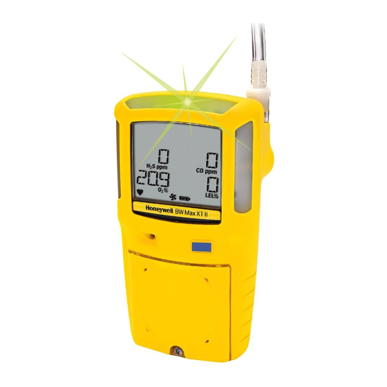
Page 12: Parts Of The Maxxt Ii
Parts of the MaxXT II Item Description Visual alarm indicators (LEDs) Pump quick connector Pump filter and moisture filter Button Alligator clip Charging connector and IR interface Diffusion cover locking screw Diffusion cover Audible alarm Liquid crystal display (LCD) BW MaxXT II User Manual... -
Page 13: Display Elements
Display Elements Description Alarm condition Automatically zero sensor indicator Numeric values Battery life indicator Pump indicator Heartbeat indicator Gas type identifiers Gas cylinder indicator Automatically span sensor indicator BW MaxXT II User Manual... - Page 14 To acknowledge a low alarm and disable the audible alarm temporarily, press . The Low Alarm Acknowledge option must be enabled in Safety Suite Device Configurator (SSDC) To acknowledge any of the Due Today alarms (calibration, bump test, pump block test), press BW MaxXT II User Manual...
-
Page 15: Activating/Deactivating The Detector
Attach any pump accessories to the detector prior to activating the detector. To deactivate the detector, press and hold until the OFF countdown completes. CAUTION The maximum hose length for sampling is 75 ft (22m). BW MaxXT II User Manual... -
Page 16: Startup Tests
Recharge the battery for 6 hours and then reactivate the detector. Refer to See "Charging the Battery" on page 88 for more information.. Audible/Visual Test All of the LCD elements display simultaneously as the detector beeps, flashes, vibrates, and activates the backlight. BW MaxXT II User Manual... - Page 17 To scroll rapidly, press and hold Note: The site ID number that is entered does not reset when the detector is deactivated. If required, enter a new site ID when the detector is again activated. BW MaxXT II User Manual...
- Page 18 The LCD displays a countdown of the time remaining (in seconds) for the pump to warm up. If the Force Block Test option is enabled, the detector performs a pump test. The following screen displays. Using your finger, block the end of the hose. The following screen displays. BW MaxXT II User Manual...
- Page 19 "Troubleshooting" on page 98 for more information. If the diffusion cover is not attached, the detector beeps and the following screen displays before continuing with the startup tests. When the diffusion cover is replaced, the detector activates the pump alarm. BW MaxXT II User Manual...
- Page 20 If the CO and/or H S sensor is enabled, the alarm setpoints for the time-weighted average (TWA) and the short-term exposure limit (STEL) display. Next, the LOW and HIGH alarm setpoints display for all of the enabled sensors. BW MaxXT II User Manual...
- Page 21 Successful Self-Test: If the self-test is successful, the following screen displays. Unsuccessful Self-Test Lockout on Self-Test Error Option Enabled: If this option is enabled and a sensor fails, the following screens display before the detector deactivates. BW MaxXT II User Manual...
- Page 22 Note: If the Auto Zero on Startup option is not enabled in Safety Suite Device Configurator (SSDC) for any of the sensors, this startup test is bypassed. If ambient air is set to be measured as 20.8% vol., the automatic oxygen calibration screen displays 20.8% instead of 20.9%. BW MaxXT II User Manual...
- Page 23 If Previous Calibration Failed If the last calibration performed was unsuccessful, the following screens display. Note: BW Technologies by Honeywell recommends the sensor(s) be calibrated immediately. Calibration Due Date (optional) The LCD displays the number of days remaining until the next calibration is due.
- Page 24 User Options. Bump Test Note: BW Technologies by Honeywell recommends to bump test the sensors before each day’s use to confirm their ability to respond to gas by exposing the detector to a gas concentration that exceeds the alarm setpoints.
- Page 25 Note: BW Technologies by Honeywell recommends the sensor(s) be bump tested immediately. The LCD next displays the number of days remaining until the next bump test is due. Force Bump Enabled (optional) If the Force Bump is enabled in Safety Suite Device Configurator (SSDC) and a sensor is overdue for a bump test, the sensor(s) must be tested to continue and enter normal operation.
- Page 26 After the detector enters normal operation, ERR displays if a sensor has failed the self- test. To determine the cause and solutions for a failed sensor, refer to See "Troubleshooting" on page 98 for more information.. BW MaxXT II User Manual...
-
Page 27: Installing Safety Suite Device Configurator (Ssdc)
SPS Website to download the software and get additional information about the product. Using Safety Suite Device Configurator (SSDC) to Configure the Detector Item Description IR and charger interface BW MaxXT II IR Link USB cable BW MaxXT II User Manual... - Page 28 Refer to the following sections in this guide for descriptions about entering data, enable- disable, and define settings. When all settings are defined, click at the bottom of the configuration window to save the new configuration of the detector. BW MaxXT II User Manual...
-
Page 29: Configuration
Serial Number Field This field displays the serial number (e.g. MA221-002767) of the detector. It can be found in the Device List View or in the Details tab (once inside the device's settings) BW MaxXT II User Manual... - Page 30 This field displays the current firmware version (e.g. v 13.000) that displays on the detector LCD during the startup tests. If new firmware is uploaded to the detector, the Firmware Version field automatically updates. Force Bump BW MaxXT II User Manual...
- Page 31 If this option is enabled, the following screen displays during the startup tests. Note: Honeywell recommends to bump test the sensors before each day’s use to confirm their ability and response to gas by exposing the detector to a gas concentration that exceeds the high alarm setpoints.
- Page 32 Note: If overdue for calibration, BW recommends the sensor(s) be calibrated immediately. Cal IR Lock Note: The auto-zero function is not affected if the CAL IR Lock option is enabled. The detector still performs the auto-zero function (if enabled). BW MaxXT II User Manual...
- Page 33 IntelliDoX Station User Manual The detector is shipped with the CAL IR Lock option disabled. Lockout on Self-Test Error (failed sensor lock) If enabled and a sensor fails during startup, the following screens display and the detector deactivates. BW MaxXT II User Manual...
- Page 34 The detector is shipped with the Lockout on Self-Test Error option disabled. Datalog Interval The Datalog Interval (seconds) field defines how often the detector records a datalog sample (every 1-120 seconds). You can find this option under the Settings tab to enter the desired value. BW MaxXT II User Manual...
- Page 35 To enter a number from 1-999, continue pressing until the desired number displays. To scroll rapidly, press and hold. The location entries are recorded in the datalogs. The detector is shipped with the Location Logging option disabled. BW MaxXT II User Manual...
- Page 36 Safe Mode If an alarm condition occurs, the LCD displays the real-time readings for each sensor. If enabled, SAFE displays continuously on the LCD unless an alarm condition occurs. BW MaxXT II User Manual...
- Page 37 Confidence Interval field. The detector is shipped with the Confidence Beep option disabled. Confidence Interval The Confidence Interval (seconds) field defines how often the confidence beep occurs (detector beeps). Enter the desired value (every 1-120 seconds). The Confidence Beep option must be enabled. BW MaxXT II User Manual...
- Page 38 Enter any type of information such as employee name, plant, area, emergency number(s), etc. Depending upon the length of the message, text will either display or scroll across the bottom line of the LCD. BW MaxXT II User Manual...
- Page 39 From the drop down menu, select the required language. When the settings are saved to the detector, the LCD displays all screens in the selected language. The detector is shipped with English displaying as the default language. BW MaxXT II User Manual...
-
Page 40: Sensor Configuration
The Sensor tab adjusts settings for each individual sensor. A separate sensor section is provided for each sensor. Note: Depending upon the sensor, the options may vary. Disable Sensor WARNING Use extreme caution when disabling a sensor. The disabled sensor cannot detect and alarm against the applicable gas. BW MaxXT II User Manual... - Page 41 Go to the Sensors tab and click on the edit button from the sensor you wish to disable. Check the box Disable Sensor Click Save The LCD automatically updates. In the following example, the CO gas type and sensor readings no longer display. BW MaxXT II User Manual...
- Page 42 Note: The Low Alarm Acknowledge option is not applicable to O If enabled, the audible alarm can be disabled during a low alarm condition. The LED and visual alarm indicators remain active until the alarm condition changes or the detector deactivates. BW MaxXT II User Manual...
- Page 43 The detector is shipped with the Low Alarm Acknowledge disabled. Low Alarm Enter the low alarm setpoints for each sensor (applicable to all sensors). Refer to See "Resetting Gas Alarm Setpoints" on page 62 for more information. for factory defined alarm setpoints. BW MaxXT II User Manual...
- Page 44 Setpoints" on page 62 for more information. for OSHA factory settings. The short term exposure limit (STEL) is the maximum permissible gas concentration a worker can be safely exposed to for short periods of time (5-15 minutes maximum). BW MaxXT II User Manual...
- Page 45 Refer to See "Resetting Gas Alarm Setpoints" on page 62 for more information. for factory alarm setpoints. Enter the TWA alarm setpoint for the H S and the CO sensor in the TWA Alarm (ppm) field. TWA is not applicable to O and LEL. BW MaxXT II User Manual...
- Page 46 To input a calibration gas follow the next steps: Select the applicable sensor and click on the edit icon. Enter the gas concentration value in the Calibration Gas (ppm) field for H S and CO. BW MaxXT II User Manual...
- Page 47 Click Save Bump Interval Note: Honeywell recommends to bump test the sensors before each day’s use to confirm their ability and response to gas by exposing the detector to a gas concentration that exceeds the high alarm setpoints. Verify that the audible and visual alarms activate. Calibrate if the readings are not within the specified limits.
- Page 48 The detector is shipped with the factory default set to 180 days. Enter the value (0-365 days) for each sensor. Enter 0 to disable the calibration interval option. Entering 0 automatically deactivates the Force Calibration user option. BW MaxXT II User Manual...
- Page 49 STEL is reached, the detector alarms to notify the worker to leave the area immediately. Enter the interval (5-15 minutes) in the STEL Interval (minutes) field. The detector is shipped with the STEL interval set to 15 minutes. BW MaxXT II User Manual...
- Page 50 (first hour) are replaced by the newest values (seventh hour). This continues for the duration of the work shift until the detector is deactivated. Enter a value ranging from 4-16 hours. The detector is shipped with the default setting of 8 hours. BW MaxXT II User Manual...
- Page 51 To find this option go to the Sensors tab and click de edit icon next to the Oxygen section. If the 20.8 Base Reading option is enabled, the detector assumes 20.8% O ambient air (factory default is 20.9% O The detector is shipped with this option disabled. BW MaxXT II User Manual...
- Page 52 When enabled, the detector automatically over-spans the LEL sensor by 5% of the span concentration to ensure the span meets CSA standards. After enabling this option in Safety Suite Device Configurator (SSDC), a calibration (manual or using the IntelliDoX) must be completed to fully enable this option. BW MaxXT II User Manual...
- Page 53 If enabled, the detector LCD displays the LEL value as % vol. assuming a methane environment. If LEL by Volume CH is enabled, a percentage value must be entered in the 50% LEL = (%CH4) field. BW MaxXT II User Manual...
- Page 54 LEL sensor has been calibrated with methane. The detector is shipped with the factory default set to 100%. Enter a K-factor (industry standard decimal value) in the Correction Factor (%) field. Values can range from 0.50 - 4.00. BW MaxXT II User Manual...
- Page 55 LEL = (%CH4) field to display the LEL reading in %vol. assuming a methane environment. Enter the equivalent methane concentration for 50% LEL as follows: North America = 2.5% Europe = 2.2% This option is only applicable to the LEL sensor. BW MaxXT II User Manual...
-
Page 57: Alarms
The LED and visual alarm indicators remain active until the alarm condition changes or the detector deactivates. Press to acknowledge the low alarm and deactivate the audible alarm. If the alarm escalates to a high, TWA, or STEL alarm, the audible alarm reactivates. BW MaxXT II User Manual... - Page 58 After 10 Vibrator alarm minutes, a activates sequence of 10 rapid sirens and alternating flashes with 1 second of silence in between (reactivates seven times) TURNING OFF displays before the detector deactivates BW MaxXT II User Manual...
- Page 59 ) and the gas concentration is below the low alarm setpoint. The LCD displays the peak concentration until the alarm condition no longer exists. Enable/disable Latching Alarms in Safety Suite Device Configurator (SSDC). Local regulations may require Latching Alarms be enabled. BW MaxXT II User Manual...
-
Page 60: Gas Alarms
Short-term exposure limit (STEL) to gas based on a 5-15 minute user-defined S and period. CO only) Maximum* Maximum (MAX) concentration encountered during work shift. (peak) * For oxygen, it is the highest or the lowest concentration encountered. BW MaxXT II User Manual... - Page 61 STEL alarms. To view the TWA, STEL, and maximum (MAX) readings, press twice rapidly. The LCD first displays the current time and date. The TWA gas exposures are displayed. Then, the STEL gas exposures are displayed. BW MaxXT II User Manual...
- Page 62 Next, the MAX readings are displayed. Finally, the CLEAR ALL readings screen is displayed. To clear the TWA, STEL, and MAX exposure readings, press when the following screen is displayed. BW MaxXT II User Manual...
- Page 63 Note: To disable an alarm, set the alarm setpoint to 0 (zero) in Safety Suite Device Configurator (SSDC). To change the factory-defined alarm setpoints, refer to See "Sensor Configuration" on page 39 for more information.. BW MaxXT II User Manual...
- Page 64 TWA/STEL/MAX exposure readings. Refer to See "Viewing and Clearing Gas Exposures" on page 60 for more information.. CAUTION Follow all safety procedures as defined by your employer. Confirm with your supervisor before clearing TWA and STEL alarms. BW MaxXT II User Manual...
-
Page 65: Sensor Alarm
The detector tests for missing or defective sensors during the startup self-test and continuously thereafter. If a sensor fails the self-test, Err displays above the gas type of the failed sensor. If a sensor fails, refer to See "Troubleshooting" on page 98 for more information.. BW MaxXT II User Manual... -
Page 66: Pump Alarm
If the pump test is successful, the detector returns to normal operation. If the pump test is unsuccessful, refer to See "Troubleshooting" on page 98 for more information. for possible causes and solutions. BW MaxXT II User Manual... -
Page 67: Low Battery Alarm
1 second of silence in between. The sequence repeats seven times. The following screens displays and the detector deactivates. To charge the detector, refer to See "Charging the Battery" on page 88 for more information.. BW MaxXT II User Manual... -
Page 69: Bump Test
Note: An IntelliDoX station (automated bump test) is required to log bump tests as an event. A manual bump test will not be logged as an event. BW MaxXT II User Manual... -
Page 70: Bump Test Using The Intellidox Station
Bump Test Using the IntelliDoX Station To perform an automated bump test, refer to the IntelliDoX User Manual. BW MaxXT II User Manual... -
Page 71: Calibration
Auto-Zero on Startup option is enabled. Activate the detector in a normal (20.9%/20.8% O ) atmosphere. If a certified calibration is required, contact BW Technologies by Honeywell. Calibration can be performed using either a 0.5 l/min manual regulator (PN: REG - 0.5) or a demand flow regulator (PN: REG-DF-1) The maximum hose length for calibration is 3 ft (0.9 m). -
Page 72: Diagnostics Protection
Disposable cylinders 0-1000 psig/70 bar Refillable cylinders 0-3000 psig/70 bar Honeywell recommends using premium grade calibration gases and cylinders that are certified to National Standards. The calibration gases must meet the accuracy of the detector. Diagnostics Protection The detector tests the ambient air (auto-zero) and the test gas that is applied (auto span) to ensure it meets expected values. -
Page 73: Connecting The Gas Cylinder To The Detector
Begin the calibration procedures. Refer to the See "Calibration Procedure" on page 74 for more information. section. When calibration is complete, disconnect the hose from the detector and the regulator. Ensure the gas cylinder is stored according to the manufacturer’s specifications. BW MaxXT II User Manual... - Page 74 Connecting the Gas Cylinder to the Detector BW MaxXT II User Manual...
-
Page 75: Calibration Procedure
Verify the calibration gas being used matches the span concentration value(s) that are set for the detector. Press and hold while the detector performs the OFF countdown. Continue to hold as the detector briefly deactivates. BW MaxXT II User Manual... - Page 76 Auto Zero Unsuccessful: If a sensor(s) fails auto zero, an error message and which sensor(s) failed displays. To determine the cause and solutions for the failed sensor(s), refer to See "Troubleshooting" on page 98 for more information.. BW MaxXT II User Manual...
- Page 77 Refer to the following for possible causes and solutions. The detector will not span a sensor if gas is not applied to the sensor, 50% of the expected gas concentration is not detected within the first 30 seconds, BW MaxXT II User Manual...
- Page 78 "Replacing a Sensor or Sensor Filter" on page 91 for more information.. If a sensor(s) fails any step of the calibration, the following screen displays. Note: If calibration is unsuccessful for a sensor(s), the calibration due date cannot be set for the failed sensor(s). BW MaxXT II User Manual...
- Page 79 S sensor has the earliest date. The H S sensor must be calibrated in 65 days. If a sensor fails to span successfully and it is past the calibration due date, the following screens display. BW MaxXT II User Manual...
- Page 80 To ensure the readings are accurate, apply the verification gas for the same amount of time as was applied to the sensor when it was calibrated. Example: H S span time 2 minutes therefore, apply verification gas for 2 minutes. BW MaxXT II User Manual...
-
Page 81: Calibrating Using The Ir Link
The system will perform an automatic Startup Scan From the Device List View tab, select the Detector by clicking on the checkbox next to the device. From the top options, select Start Bump/Cal The Start Bump/Cal Test box displays. BW MaxXT II User Manual... - Page 82 Refer to See "Auto Span" on page 76 for more information. to complete calibration. Note: To calibrate using the IntelliDoX, refer to the IntelliDoX User Manual and the Safety Suite Device Configurator (SSDC) Operator’s Manual. BW MaxXT II User Manual...
-
Page 83: Event Logs
Serial number of the detector Start time of alarm Type, level, and duration of alarm Status of sensor Peak exposure level (ppm or %) Status of the detector Detector user Supervisor Location Definables (employee information) BW MaxXT II User Manual... -
Page 84: Datalogs
Gas readings STEL and TWA readings (H S and CO only) Alarm setpoints Options enabled/disabled Sensor status Pump status Logging intervals Language detector is set to display Calibrations performed Bump tests performed Battery readings Temperature readings BW MaxXT II User Manual... -
Page 85: Bump And Calibration Results
Next bump test due date Datalog interval STEL period Pump enabled/disabled Audible and visual indicator status Sensor type and sensor status Alarm status Sensor status Inlet(s) used Definables (employee information) Downloading Datalogs and Event Logs BW MaxXT II User Manual... - Page 86 IntelliDoX Station. Refer to the Safety Suite Device Configurator (SSDC) Operator’s Manual. Software Requirements Safety Suite Device Configurator (SSDC) and Excel software are required to create spreadsheet reports of the event logs, datalogs, and bump and calibration results. BW MaxXT II User Manual...
-
Page 87: Maintenance
Clean the exterior with a soft damp cloth. Do not use solvents, soaps, or polishes. Do not immerse the detector in liquids. Maximum Hose Length for Sampling The maximum hose length for sampling is 75 ft (22m). BW MaxXT II User Manual... -
Page 88: Battery Maintenance And Cautions
Do not calibrate the detector during or immediately after charging the battery. Warning: The BW MaxXT II uses a lithium battery (MX-BAT01) that may present a risk of fire or chemical burn hazard if misused. Do not disassemble, heat above 212° (100°C), or incinerate. -
Page 89: Charging The Battery
Charging the Battery Connecting the Charger Adapter Item Description IR and charger interface BW MaxXT II Charger adapter Charger cable WARNING The detector must be charged in a safe area that is free of hazardous gas in temperatures of 32°F to 113°F (0°C to 45°C). - Page 90 To obtain full operating capacity, allow the battery to fully charge and discharge three times. To achieve the maximum number of charges, ensure the battery is charged between 32°F and 113°F (0°C and 45°C). Do not charge the battery in temperatures above 113°F (45°C). BW MaxXT II User Manual...
-
Page 91: Replacing The Battery
Replacing the Battery To replace the lithium battery, refer to See "Replacement Parts and Accessories" on page 102 for more information. to order the (XT-BAT-K1) kit that includes the Replacing the BW MaxXT II Battery Operator’s Manual. BW MaxXT II... -
Page 92: Replacing A Sensor Or Sensor Filter
Do not expose a sensor to vapors from inorganic solvents such as fumes from paint thinners, or organic solvents such as benzoic acids and acrylic acids). Replacing a Sensor or Sensor Filter Item Description Front shell LEL sensor PCB screws (2) Pump Rear shell BW MaxXT II User Manual... - Page 93 Because the pump hose is connected to the rear shell and front shell pump, carefully remove the rear shell by lifting upward and tilting to the left. The front and rear shells are laying flat side by side. BW MaxXT II User Manual...
- Page 94 Replace the machine screws using 3-4 in-lbs. torque. Tighten the screws using a crisscross pattern to ensure a proper seal. Replace the pump inlet and the pump inlet screw. Activate the detector and calibrate the sensor(s). Refer to See "Calibration" on page 70 for more information.. BW MaxXT II User Manual...
-
Page 95: Replacing The Pump Filters
The moisture filter will not typically require frequent changes. If moisture is drawn through the tubing, replace both the moisture filter and the particulate filter immediately. To change the particulate or the moisture filter, refer to the following information. BW MaxXT II User Manual... - Page 96 Depending upon the circumstance, replace either just the particulate filter or both. Refer to Particulate Filters and Moisture Filters in this section. Reattach the pump inlet and replace the screw. Tighten the screw using 3-4 in-lbs. torque. Do not overtighten. BW MaxXT II User Manual...
- Page 97 Successful: If the block test is successful, the detector completes the startup test and enters normal operation. Unsuccessful: If the block test is unsuccessful, the detector deactivates. For causes and possible solutions, refer to See "Troubleshooting" on page 98 for more information.. BW MaxXT II User Manual...
-
Page 98: Replacing The Pump
Replacing the Pump To obtain a new pump (XT-RPUMP-K1) and the Pump Replacement Operator’s Manual, refer to See "Replacement Parts and Accessories" on page 102 for more information.. BW MaxXT II User Manual... -
Page 99: Troubleshooting
Battery" on page 88 for more The detector does not information.. activate. Damaged or defective Contact BW Technologies by Honeywell detector Charge the battery. Refer to See "Charging Automatic deactivation the Battery" on page 88 for more due to depleted battery information.. - Page 100 "Resetting Gas Alarm Setpoints" on page 62 for more information.. Battery has been charging for 6 hours. Charging Battery is fully charged and is ready for Battery is trickle charging indicator on LCD shows the operation. battery is still charging. BW MaxXT II User Manual...
- Page 101 Battery is depleted below indicator does not light after charging, display when charging. normal levels contact BW Technologies by Honeywell. Diffusion cap is off or not Attach diffusion cap. Ensure seal is tight. attached correctly. There is a blockage in the Clear the blockage.
-
Page 103: Replacement Parts And Accessories
Quad calibration kit with regulator, quad gas cylinder (CG-Q34-4), CK-Q34-4 hose, and carrying case Quad calibration kit with regulator, quad gas cylinder (CG-Q58-4), CK-Q58-4 hose, and carrying case XT-SS-1 Sensor filter for BW MaxXT II, Kit of 2 BW MaxXT II User Manual... - Page 104 Hydrophobic (moisture) filters (kit of 50) XT-C01-MC5 BW MaxXT II multi-unit charger GA-PA-1* Charging adapter BW MaxXT II docking module (for use w/ IntelliDoX) and charging DX-MAXXT cable GA-USB1-IR IR connectivity kit (includes USB cable) XT-SCREWK1 Replacement screw kit (40 screws and screwdriver)
-
Page 105: Specifications
User field options: Startup message, lockout on self-test error, safe mode, confidence beep, latching alarm, force calibration, cal IR lock, force bump, location logging, force block test, set datalog interval, set confidence interval, language selection. BW MaxXT II User Manual... - Page 106 Rechargeable battery (MX-BAT01) Temperature Code Lithium Polymer -20°C ≤ Ta ≤ +50°C Battery charger: Honeywell BW™ MaxXT II Charging Adapter First-time charge: 6 hours Normal charge: 6 hours Warranty: 2 years including sensors Approvals Approved by CSA to both U.S. and Canadian Standards CAN/CSA C22.2 No.
-
Page 107: General Datalogger Specifications
Operation: Requires no user intervention (automatic) Compatible with: Desktop PC computer or laptop Operating system: Windows XP and Windows Vista Download via: IR device (IR Link adapter or IntelliDoX) Software required: Safety Suite Device Configurator (SSDC)and Microsoft Excel BW MaxXT II User Manual... - Page 108 P/N 129541-L3 EN Rev E ©2021, October BW MaxXT II User Manual...
Need help?
Do you have a question about the BW MaxXT II and is the answer not in the manual?
Questions and answers