Table of Contents
Advertisement
Quick Links
Download this manual
See also:
Operator's Manual
Advertisement
Table of Contents

Related Manuals for Chameleon Antenna EMCOMM III


Summary of Contents for Chameleon Antenna EMCOMM III
- Page 1 EMCOMM III Base Antenna Operator’s Manual Nevada - USA WWW.CHAMELEONANTENNA.COM VERSATILE – DEPENDABLE – STEALTH – BUILT TO LAST...
-
Page 2: Table Of Contents
10 watts or above 14 MHz. Never use this antenna near RF sensitive medical devices, such as pacemakers. All information on this product and the product itself is the property of and is proprietary to Chameleon Antenna . Specifications are subject to change without prior notice. EMCOMM III Base Page 2... -
Page 3: Introduction
11-year solar cycle. A detailed explanation of the theory of HF radio wave propagation is beyond the scope of this operator’s manual, but an understanding of the basic principles will help the operator decide what frequency and which of the EMCOMM III Base’s configurations will support their communication requirements. EMCOMM III Base... -
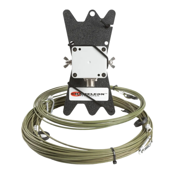
Page 4: Parts Of The Antenna
2 to 10 MHz. Frequencies of 2 – 4 MHz are typical at night and 4 – 8 MHz during the day. Parts of the Antenna The EMCOMM III Base antenna is comprised of the following components: EMCOMM III Base... - Page 5 Do not open the Matching Transformer, you may damage the weather seal or internal components. b. Line Winder The Line Winder is used to store the Antenna Wire (g) and enabling easy installation of the EMCOMM III Base antenna. Plate 2. EMCOMM III Base Top View.
- Page 6 Antenna Wire (g). 3/16” Dacron Rope 3/16” Dacron Rope (not pictured and not supplied) is used to suspend components of the EMCOMM III Base antenna at the proper height or anchor them to the ground, depending upon the antenna configuration.
-
Page 7: Antenna Configurations
EMCOMM III Base antenna. Antenna Configurations The EMCOMM III Base antenna can be installed in a number of effective configurations. Table (2) shows the four antenna configurations described in this manual. The table can assist the operator to quickly select the most appropriate antenna configuration to meet their operational requirements. -
Page 8: Inverted "L" Configuration
Inverted “L” Configuration The EMCOMM III Base antenna, Inverted “L” configuration, see figure (1), is a multi-band short to medium range HF antenna. It is a general-purpose antenna and when installed at a height of around 35 feet, will provide good sky wave propagation (including NVIS). -
Page 9: Half Square Configuration
Half Square Configuration The EMCOMM III Base antenna, Half Square configuration, see figure (3), is a multi-band short to long range HF antenna. In this configuration, performance is enhanced from 7 to 20 MHz (40 to 17 meters) while somewhat reduced above and below those frequencies. -
Page 10: End-Fed Sloper
End-Fed Sloper The EMCOMM III Base antenna End-Fed Sloper configuration, see figure (4), is a medium to long range multi-band HF antenna. The End-Fed Sloper is a good choice if you already have a metal antenna tower or mast. The tower or mast is used as the ground counterpoise in this configuration. -
Page 11: Troubleshooting
3/16” Dacron Rope. Around 100 feet in two 50 foot lengths required for most configurations. • Coaxial Cable Assembly. 50 feet of RG-58 with integrated RFI Choke. Used to connect the EMCOMM III Base to the radio set. This is a highly recommended accessory if you are not using a CHA RFI CHOKE. -
Page 12: Specifications
15 degrees • Personnel Requirements and Setup Time: one trained operator, less than 30 minutes • Far Field plots for the three basic and special EMCOMM III Base antenna configurations are shown in figures (4) through (7) FREQUENCY 10.1 14.1... - Page 13 Figure 4. Inverted “L” Far Field Plot. Figure 6. End-Fed Inverted “V” Field Plot. EMCOMM III Base Page 13...
- Page 14 Figure 6. Half Square Far Field Plot. Figure 7. End-Fed Sloper Far Field Plot. EMCOMM III Base Page 14...
- Page 15 Chameleon Antenna Products The following products are available for purchase at Chameleon Antenna Go to http://chameleonantenna.com for ordering and more information. CHA P-LOOP 2.0 - The CHA P-LOOP 2.0 was designed color of the lid and the base connector, which is black with portability, ease of use simplicity, ruggedness instead of gray.
-
Page 16: Chameleon Antenna Tm Products
2. 1987, Tactical Single-Channel Radio Communications Techniques (FM 24-18), Department of the Army, Washington, DC. 3. Turkes, Gurkan, 1990, Tactical HF Field Expedient Antenna Performance Volume I Thesis, U.S. Naval Post Graduate School, Monterey, CA. EMCOMM III Base Page 16...
Need help?
Do you have a question about the EMCOMM III and is the answer not in the manual?
Questions and answers