Table of Contents
Advertisement
Advertisement
Table of Contents

Subscribe to Our Youtube Channel
Related Manuals for Ammann ARX 36-2 KU St V 2022


Summary of Contents for Ammann ARX 36-2 KU St V 2022
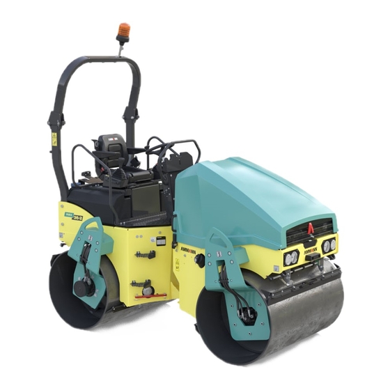
- Page 1 ARX 36-2 ARX 40-2 ARX 45-2 TANDEM ROLLER KUBOTA V2403-M-E3B EU Stage IIIA / U.S. EPA Tier 4i OPERATING MANUAL EDITION 04/2020 EN ARX 36-2 KU St V / T4i From Serial No. 5953002 ARX 40-2 KU St V / T4i From Serial No. 5963018 ARX 45-2 KU St V / T4i From Serial No.
- Page 3 / Das Original der EG-/EU-Konformitätserklärung wird mit den Unterlagen während des Versands der Maschine mitgeliefert. Výrobce / Manufacturer / Hersteller: Ammann Czech Republic a.s. Adresa / Address / Adresse: Náchodská 145, CZ-549 01 Nové Město nad Metují, Czech Republic IČ...
- Page 4 / Das Original der EG-/EU-Konformitätserklärung wird mit den Unterlagen während des Versands der Maschine mitgeliefert. Výrobce / Manufacturer / Hersteller: Ammann Czech Republic a.s. Adresa / Address / Adresse: Náchodská 145, CZ-549 01 Nové Město nad Metují, Czech Republic IČ...
- Page 5 / Das Original der EG-/EU-Konformitätserklärung wird mit den Unterlagen während des Versands der Maschine mitgeliefert. Výrobce / Manufacturer / Hersteller: Ammann Czech Republic a.s. Adresa / Address / Adresse: Náchodská 145, CZ-549 01 Nové Město nad Metují, Czech Republic IČ...
- Page 7 Congratulations on your purchase of the AMMANN compaction machine. This modern compaction machine is characterised by simple operation and maintenance and is the product of many years of experience of the AMMANN company in compaction machines, espe- cially road rollers. In order to avoid faults due to improper operation and maintenance, we request you to read this operating manual with great care and keep it for later reference.
- Page 8 All dimensions and weights are approximate, and therefore not binding. Ammann Czech Republic a.s. reserves the right to perform modifications at any time with no obligation to inform the machine user. If you identify any differences between the machine operated by you and the information contained in this publication, contact your local dealer.
- Page 9 SAFETY NOTICE SIGNS The notice warns of a serious risk of personal injury or other perso- nal hazards. The notice warns of possible damage to the machine or its parts. The notice warns of the necessity of environmental protection. ! CAUTION! As used in this operating manual, the terms right, left, front and rear indicate sides of the machine moving forward.
-
Page 10: Table Of Contents
Contents Contents ................................4 SPECIFICATION MANUAL ........................9 1.1 Basic data ..............................10 1.2 Dimensional drawing of the machine ....................12 1.3 Technical data ............................14 OPERATING MANUAL ..........................19 2.1 Main safety precautions ........................21 2.1.1 Safety precautions during operation of the machine ..........................21 2.1.1.1 Before compacting works are started ................................21 2.1.1.2 Work in the dangerous area ....................................21 2.1.1.3 Ensurance of safety measures by the provider ............................22 2.1.1.4 Protective frame ROPS ......................................22... - Page 11 OPERATING MANUAL 2.4 Machine disposal after its service life ....................39 2.5 Machine description ..........................40 2.6 Controls and checking instruments ....................42 2.6.1 Dashboard and control panels ..................................43 2.7 Machine operation and use .........................60 2.7.1 Starting the engine .......................................61 2.7.2 Drive and reverse drive ......................................65 2.7.3 Stopping the machine and turning off the engine ..........................73 2.7.4...
- Page 12 Contents MAINTENANCE MANUAL ........................101 3.1 Safety and other measures during maintenance of the machine ..........103 3.1.1 Safety during machine maintenance ................................103 3.1.2 Fire protection when operating fluids are changed ..........................103 3.1.3 Environmental and hygiene principles ............................... 104 3.2 Specification of operating fluids .......................105 3.2.1 Engine oil ..........................................
- Page 13 OPERATING MANUAL Every 100 hours of operation (weekly) .....................132 3.6.17 Air filter cleaning ......................................... 132 3.6.18 Cleaning the water separator on the fuel filter ............................133 3.6.19 Machinze lubrication ......................................134 3.6.20 Tyre pressure check ......................................135 Every 250 hours of operation (every 3 months) ................136 3.6.21 Fuel filter replacement .....................................
- Page 14 Contents 3.7 Troubleshooting ..........................163 3.7.1 List of error codes displayed on the display .............................. 164 3.8 Appendices ............................172 Wiring diagram ............................................. 172 Hydraulic diagram ARX 36-2, ARX 40-2, ARX 45-2 ..............................178 Hydraulic diagram ARX 40-2C, ARX 45-2C .................................. 180 Hydraulic diagram –...
-
Page 15: Specification Manual
SPECIFICATION MANUAL 1 SPECIFICATION MANUAL ARX 36-2 ARX 40-2 ARX 45-2 (Kubota Tier 4 interim) ARX 36-2 T4i, ARX 40-2 T4i , ARX 45-2 T4i... -
Page 16: Basic Data
Basic data Machine description Please fill in the following data: Tandem machine with an articulated frame and two smooth (see nameplate and Kubota engine nameplate) drums. Both drums are hydrostatic-driven and vibrating. The rear drum vibration is switchable. The concept of the frame allows compacting close to the walls and elevated kerbs on Machine type both sides of the machine. - Page 17 SPECIFICATION MANUAL Serial number of the machine frame 590052 Position of the ROPS nameplate ROPS nameplate 590039 Engine nameplate position Serial number of the Kubota engine 590049 593077 ARX 36-2 T4i, ARX 40-2 T4i , ARX 45-2 T4i...
-
Page 18: Dimensional Drawing Of The Machine
Dimensional drawing of the machine 590048B ARX 36-2 T4i, ARX 40-2 T4i , ARX 45-2 T4i... - Page 19 SPECIFICATION MANUAL 588611 ARX36-2 ARX40-2 ARX40-2C ARX45-2 ARX45-2C mm (in) EU Stage IIIA / U.S. EPA Tier 4i 1950 (76.8) 1950 (76.8) 2000 (78.7) 1950 (76.8) 2000 (78.7) (33.5) (33.5) 850 / 812 (33.5 / 32.0) (33.5) 850 / 812 (33.5 / 32.0) (13.0) (13.0) (13.0)
-
Page 20: Technical Data
18 (40) 17.8 (40) Weight of Canopy kg (lb) 35 (80) 35 (80) 35 (80) 35 (80) 35 (80) Weight of Ammann edge cutter kg (lb) 60 (130) 60 (130) 60 (130) 60 (130) 60 (130) Driving characteristics Maximum transport speed km/h (MPH) 10 (6.2) - Page 21 SPECIFICATION MANUAL ARX 36-2 ARX 40-2 ARX 40-2C ARX 45-2 ARX 45-2C EU Stage IIIA / U.S. EPA Tier 4i Engine Manufacturer Kubota Kubota Kubota Kubota Kubota V2403-M- V2403-M- V2403-M- V2403-M- V2403-M- Type Power according to SAE J1995 34.1 34.1 34.1 34.1 34.1 Number of cylinders...
- Page 22 Technical data ARX 36-2 ARX 40-2 ARX 40-2C ARX 45-2 ARX 45-2C EU Stage IIIA / U.S. EPA Tier 4i Wiring Voltage Battery capacity Noise and vibration emissions Measured sound pressure level A, L at the operator's position (platform) * Uncertainty K Guaranteed sound power level A, L Declared highest weighted effective value of vibration acceleration trans-...
- Page 23 SPECIFICATION MANUAL Notes ARX 36-2 T4i, ARX 40-2 T4i , ARX 45-2 T4i...
- Page 24 ARX 36-2 T4i, ARX 40-2 T4i , ARX 45-2 T4i...
-
Page 25: Operating Manual
OPERATING MANUAL 2 OPERATING MANUAL ARX 36-2 ARX 40-2 ARX 45-2 (Kubota Tier 4 interim) ARX 36-2 T4i, ARX 40-2 T4i , ARX 45-2 T4i... - Page 26 ARX 36-2 T4i, ARX 40-2 T4i , ARX 45-2 T4i...
-
Page 27: Main Safety Precautions
Main safety precautions OPERATING MANUAL 2.1.1 Safety precautions during operation of 2.1.1.2 Work in the dangerous area the machine Any damage to the utility lines must be immediately reported to their provider, and at the same time measures must be taken Safety measures given in the individual chapters of the tech- to prevent unauthorized persons from entering the dangerous nical documentation supplied with the machine must be sup-... -
Page 28: Ensurance Of Safety Measures By The Provider
Main safety precautions 2.1.1.3 Ensurance of safety measures by the 2.1.1.4 Protective frame ROPS provider When the protection frame ROPS is used: • He must ensure that the machine is operated only under • the machine frame must not be damaged (broken, bent, conditions and only for purposes it is technically capable of etc.) in the connection point according to conditions specified by the manufacturer and... -
Page 29: Requirements For The Qualification Of Machine Operators
OPERATING MANUAL 2.1.2 Requirements for the qualification of machine operators Only a person having been trained according to ISO 7130 and other local and national instructions and standards specified for operators of this group of machines, is allowed to operate the machine. -
Page 30: Driver's Obligations
Main safety precautions 2.1.3 Driver's obligations • • After a warning alarm, the operator may put the machine Before starting operation of the machine, the machine op- erator is obliged to get familiar with instructions stated in into operation only when all workers have left the endan- the documentation supplied together with the machine, gered area. -
Page 31: Forbidden Activities - Safety And Guarantee
OPERATING MANUAL 2.1.4 Forbidden activities – safety and guarantee The following is forbidden • Working with the machine in a protected zone of electric lines or substations. • Using the machine in case of an evident defect of the ma- •... - Page 32 Main safety precautions 590041B ARX 36-2 T4i, ARX 40-2 T4i , ARX 45-2 T4i...
-
Page 33: Safety Notices And Signs Applied On The Machine
OPERATING MANUAL 2.1.5 Safety notices and signs applied on the machine Read the operating manual Get perfectly familiar with the machine operation and maintenance according to the operating manual! 2946bz Pinch points Maintain a safe distance from the machine; there is a dan- ger of squeezing by the machine between the front and rear frames. - Page 34 Main safety precautions 3863 Safety belt Fasten the safety belt before the machine starts moving. 3863bz Keep calm and adjust Turn off the engine and remove the key from the ignition box before performing maintenance or repairs. 2939 2584bz Washing the machine with water Dangerous situation.
- Page 35 OPERATING MANUAL Hydraulic oil drain plug 3960 3960 Engine oil drain plug 3212 3212 Fuel drain plug 3213 3213 2151 Fuelling 2151bz Suspension hole When lifting, suspend the machine only in these holes. 2153bz ARX 36-2 T4i, ARX 40-2 T4i , ARX 45-2 T4i...
- Page 36 Main safety precautions Fastening hole When transporting, fasten the machine only in these holes. 3048bz Suspension diagram To lift the machine, use slings with a sufficient lifting ca- pacity according to chapter Loading the machine. Before hanging, lock the articulation of the machine. 590073 Set of filters 4005...
-
Page 37: Manual Signals
OPERATING MANUAL 2.1.6 Manual signals Signals given by an assistant operator if the operator cannot see the travelling or working area or work devices of the machine. The following principles must be observed: • For communication purposes, only a limited number of sig- nals must be used. - Page 38 Main safety precautions Watch out! Sig. 2 Watch out, danger! Sig. 3 SIGNALS FOR DRIVE Travel Sig. 4 Slow forward drive – towards me Sig. 5 ARX 36-2 T4i, ARX 40-2 T4i , ARX 45-2 T4i...
- Page 39 OPERATING MANUAL Slow backward drive – away from me Sig. 6 Drive to the right Sig. 7 Drive to the left Sig. 8 Short distance travel Sig. 9 ARX 36-2 T4i, ARX 40-2 T4i , ARX 45-2 T4i...
-
Page 40: Environmental And Hygiene Principles
Environmental and hygiene principles 2.2.1 Hygiene principles 2.2.2 Environmental principles • Discarded operating fluids of individual systems of the ma- chine and also some of its parts become hazardous wastes with dangerous properties for the environment. This category of waste products includes in particular: When operating and storing the machines, the user is organic and synthetic lubricating materials, oils and fu- obliged to observe general principles of health and envi-... -
Page 41: Preservation And Storage
Preservation and storage 2.3.1 Short-term preservation and storage for 2.3.2 Preservation and storage of the machine 1–2 months for a period over 2 months Wash and clean the entire machine carefully. Before parking the For machine shut-down, the same principles are applicable as machine for preservation and storage, run the engine to warm it for the short-term preservation. - Page 42 Preservation and storage 588589A ARX 36-2 T4i, ARX 40-2 T4i , ARX 45-2 T4i...
-
Page 43: Machine Depreservation
OPERATING MANUAL 2.3.3 Machine depreservation • Check all parts of the machine for damage during storage and for missing parts. If the machine has been preserved, remove the preserva- tive agents as follows: Wash off the preservative agents using a high-pressure stream of hot water with common degreasers: Wash the machine while observing environmental principles. - Page 44 ARX 36-2 T4i, ARX 40-2 T4i , ARX 45-2 T4i...
-
Page 45: Machine Disposal After Its Service Life
• the machine manufacturer or accredited contracting service organizations authorized by the manufacturer. The machine manufacturer Ammann shall not be liable for damage to the health of users or environmental dam- age caused by non-compliance with the above mentioned rules. -
Page 46: Machine Description
Machine description 595012 ARX 36-2 T4i, ARX 40-2 T4i , ARX 45-2 T4i... - Page 47 OPERATING MANUAL Legend: 1 - Front frame 2 - Rear frame 3 - Front drum 4 - Rear drum 5 - Engine 6 - Travel hydraulic motor 7 - Vibration hydraulic motor 8 - Steering joint 9 - Hydraulic oil level indicator 10 - Fuel tank 11 - Sprinkling tank 12 - Sprinkling filter...
-
Page 48: Controls And Checking Instruments
Controls and checking instruments 595001B ARX 36-2 T4i, ARX 40-2 T4i , ARX 45-2 T4i... -
Page 49: Dashboard And Control Panels
OPERATING MANUAL 2.6.1 Dashboard and control panels Legend: A - Brake test button B - Calibration button 1 - Beacon and rear light change-over switch 2 - Differential lock button 3 - Engine speed selector 4 - Travel mode switch 5 - Sprinkling potentiometer 6 - Emergency brake button 7 - Vibration mode selector switch (manual mode / automatic mode) - Page 50 Controls and checking instruments 595002B ARX 36-2 T4i, ARX 40-2 T4i , ARX 45-2 T4i...
- Page 51 OPERATING MANUAL Brake test button (A) Big working speed: Used to check the correct brake function. Frequency II 100% vibration capacity Calibration button (B) 100% travel speed (depending on the transport and working speed change-over switch) Used to calibrate functions: 100% engine speed •...
- Page 52 Controls and checking instruments 595003C ARX 36-2 T4i, ARX 40-2 T4i , ARX 45-2 T4i...
- Page 53 OPERATING MANUAL Vibration mode selector switch (manual mode / automatic mode) (7) 3726G • Manual vibration mode – vibration can be switched on when the machine is stationary or moving. Drum sprinkling – vibration can be switched on when the machine is statio- nary or moving.
- Page 54 Controls and checking instruments 595A003C ARX 36-2 T4i, ARX 40-2 T4i , ARX 45-2 T4i...
- Page 55 OPERATING MANUAL Travel control – right (standard) (11) Travel control – left (optional) The travel control is used to set the engine speed, the parking The travel control is used to set the engine speed, the parking brake, forward/reverse direction and the travel speed of the ma- brake, forward/reverse direction and the travel speed of the ma- chine.
- Page 56 Controls and checking instruments 595004C ARX 36-2 T4i, ARX 40-2 T4i , ARX 45-2 T4i...
- Page 57 OPERATING MANUAL Ignition box (19) Vibration switch (12) 0 - OFF 2612 I - ON II - Engine glowing Press the switch to turn on/off the vibration function. III - Engine starting Sprinkling switch (13) Display (20) Instrument to display parameters and functions of the engine AMN83 and of the machine.
- Page 58 Controls and checking instruments 590061A Display (20) Instrument to display parameters and functions of the engine and of the machine. Indicator lamps 22 - Error message indicator lamp 32 - Dipped lights indicator lamp 23 - Battery charging indicator lamp 33 - Direction light indicator lamp 24 - Engine oil pressure indicator lamp 34 - Filter clogging indicator lamp...
- Page 59 OPERATING MANUAL Error message indicator lamp (22) Hydraulic oil temperature indicator lamp (26) AMN58 2635 The error message indicator lamp lights up when the control The hydraulic oil temperature indicator lamp lights up when the system detects an error. At the same time, the error code ap- oil temperature exceeds 85 °C.
- Page 60 Controls and checking instruments Indicator lamp of blocking the start of DPF (Die- Parking brake indicator lamp (30) sel Particulate Filter) regeneration (36) 2703 AMN442 The lighting indicator lamp indicates that the parking brake was The machine is not equipped with a DPF. enabled.
- Page 61 OPERATING MANUAL Seat Seat adjustment Backrest inclination adjustment Seat springing stiffness Longitudinal seat travel Cross seat travel Seat springing stiffness Turn the switch (2) to set stiffness according to driver’s weight between 50 and 120 kg (110 - 265 lb). 615025 Adjust the seat before driving the machine.
- Page 62 Controls and checking instruments Movement blocking If the driver is not sitting on the seat, moving off is blocked. In this case, moving the travel control out of the parking brake (P) position immediately switches off the engine. To enable engine start, sit on the seat and set the travel control to the parking brake position (P).
- Page 63 OPERATING MANUAL Fuse box F1 – 7.5 A ..Parking lights F2 – 7.5 A ..Tail lights, licence plate light F3 – 15 A ...Headlamps F4 – 15 A ...Rear light, ROPS lights, beacon, green beacon, monitoring device F5 – 5 A ....Direction indicators F6 –...
- Page 64 Controls and checking instruments Dashboard cover The cover protects the dashboard from: • weather effects • vandalism • handling by others The cover of the dashboard can be locked with a padlock; the padlock is not delivered in the machine equipment. 588802 588801 ARX 36-2 T4i, ARX 40-2 T4i , ARX 45-2 T4i...
- Page 65 OPERATING MANUAL Engine bonnet The bonnet protects the engine from: • weather effects • vandalism • handling by others The bonnet of the engine can be locked with a padlock; the pad- lock is not delivered in the machine equipment. 611014 611013 ARX 36-2 T4i, ARX 40-2 T4i , ARX 45-2 T4i...
-
Page 66: Machine Operation And Use
Machine operation and use 595005B ARX 36-2 T4i, ARX 40-2 T4i , ARX 45-2 T4i... -
Page 67: Starting The Engine
OPERATING MANUAL 2.7.1 Starting the engine Daily before starting the engine, check the oil level in the engine and in the hydraulic tank, fuel level in the fuel tank and water level in the water tank. Check that there are no loosened, worn or missing parts on the machine. - Page 68 Machine operation and use 590A053 ARX 36-2 T4i, ARX 40-2 T4i , ARX 45-2 T4i...
- Page 69 OPERATING MANUAL Start-up procedure using leads from an external power supply: The starting supply from the external power supply must be 12 V. Always follow the undermentioned operation sequence. 1/ Connect one end of the (+) pole of the cable to the (+) pole of the discharged battery. 2/ Connect the other end of the (+) pole of the cable to the (+) pole.
- Page 70 Machine operation and use 595006B ARX 36-2 T4i, ARX 40-2 T4i , ARX 45-2 T4i...
-
Page 71: Drive And Reverse Drive
OPERATING MANUAL 2.7.2 Drive and reverse drive Before moving off, check that the articulation joint of the machine is locked. Use the warning horn to signal that the engine is starting and wait long enough so that all persons could leave the area around the machine or under the machine in time! Before moving off, check that the area in front of and behind the machine is empty and that there are no persons or obstructions there! - Page 72 Machine operation and use 595006B ARX 36-2 T4i, ARX 40-2 T4i , ARX 45-2 T4i...
- Page 73 OPERATING MANUAL Travel speed selection • The travel speed is set on the active travel control. Set and leave the inactive travel control in the parking brake position (P). • The travel speed corresponds to the deflection of the travel control (11) from the zero position (0) at the given engine speed (3) and mode of operation (4) of the machine.
- Page 74 Machine operation and use 595007B ARX 36-2 T4i, ARX 40-2 T4i , ARX 45-2 T4i...
- Page 75 OPERATING MANUAL Machine travel and reversing with vibration It is forbidden to enable the vibration when the machine is standing. If the parking brake indicator lamp (30) is on, move the travel control (11) from the parking brake (P) position to the (0) position. Manual mode Use the vibration mode selector (7) to set the manual mode.
- Page 76 Machine operation and use ARX 36-2 T4i, ARX 40-2 T4i , ARX 45-2 T4i...
- Page 77 OPERATING MANUAL MAX 30% For the maximum permissible slope gradient when dri- MAX 40% ving uphill and across the slope gradient, see figures. The given values will be lower depending on adhesive conditions and the instantaneous weight of the machine! Prevent potential danger and pay extra attention to the adherence to permitted slope gradients.
- Page 78 Machine operation and use 595008B ARX 36-2 T4i, ARX 40-2 T4i , ARX 45-2 T4i...
-
Page 79: Stopping The Machine And Turning Off The Engine
OPERATING MANUAL 2.7.3 Stopping the machine and turning off the engine Turn off the vibration with the vibration switch (12). Stop the machine by changing the travel control (11) to the neutral position (N). Brake the machine by changing the travel control (11) to the brake position (P). Set the engine speed control (19) to the idle speed. - Page 80 Machine operation and use 595009B ARX 36-2 T4i, ARX 40-2 T4i , ARX 45-2 T4i...
-
Page 81: Machine Parking
OPERATING MANUAL 2.7.5 Machine parking Shut down the machine on a flat and solid surface where there is no potential natural hazard (e.g. landslides, flooding). Change the travel control (11) to the brake position (P). Switch over the key in the ignition box (19) to the position “0”, take out the key from the ignition box and close the lid. Turn off the battery disconnector if it is installed in the machine. - Page 82 Machine operation and use 595010B ARX 36-2 T4i, ARX 40-2 T4i , ARX 45-2 T4i...
-
Page 83: Sprinkling
OPERATING MANUAL 2.7.7 Sprinkling The water level in the tank is shown on the indicator (1). Hole to fill the water tank (2). Check the water level in the tank before putting the machine into operation. Turn on the sprinkling with the sprinkling potentiometer (5). Position 0 –... -
Page 84: Infrathermometer (Optional)
Machine operation and use 2.7.9 Infrathermometer (optional) It is activated by turning on the key in the switch box (19) and it displays the temperature of the bitumen surface being rolled. The measured temperature in °C is indicated on the display. Control In the following text, the “OK button”... - Page 85 OPERATING MANUAL The infra thermometer display will light up. 590004F Switch over with the MODE button (1) until °C appears on the display. 590002F Switch over with the UP and DOWN arrows (2) until °F appears on the display. 590003F Set the current output of the infra thermometer.
- Page 86 Machine operation and use • Switch over with the UP and DOWN arrows (2) until 4–20 mA appears on the display. 590007F Set the minimum temperature. • Switch over with the MODE button (1) until the “u” symbol appears on the display. 590008F •...
- Page 87 OPERATING MANUAL • Switch over with the UP and DOWN arrows (2) until the va- lue of 932.0 °F appears on the display. 590010F • Mount the cover. 595053 Turn the key in the ignition box to the “I“ position. CAL008 Sit in the driver’s seat (activation of the seat switch).
- Page 88 Machine operation and use CAL007 After 5 seconds, the display shows B1 and, at the same time, the error message indicator lamp (22) starts flashing. CAL0021 Using the Select button (13), scroll to the B2 tab ( Fahrenheit/ Celsius temperature unit selection) and press OK (12) to confirm. tEMP CAL005 Use the Select button (13) to set the desired unit and press OK...
- Page 89 OPERATING MANUAL Use the Select button (13) to scroll to the B12 tab and press the calibration button (B) for 5 seconds. CAL007 While the button is held down, the display shows the “Saving” status. If the parameters are OK, they are saved and the display shows the “Saved”...
-
Page 90: Rops Lifting And Lowering
Machine operation and use 2.7.10 ROPS lifting and lowering ROPS key There is a ROPS key attached under the engine bonnet on the left. The ROPS key assists the operator when lifting and lowering the ROPS. D595021 ROPS lifting Climb on the driver’s stand. Remove the split pin. - Page 91 OPERATING MANUAL Remove the inner clevis pins on the top right and top left of the ROPS. Pull the ROPS fully up. 590083 Install the clevis pins back. Use the ROPS key to tighten the clevis pins. 590084 Lubricate the clevis pins e.g. with the Never Seez mounting paste. Insert the split pins into the clevis pins.
- Page 92 Machine operation and use ROPS lowering Climb on the driver’s stand. Remove the split pins. Remove the inner clevis pins on the top right and top left of the ROPS. Use the ROPS key to loosen the clevis pins. Slightly tilt off the ROPS. Be careful not to cross the centre of gravity.
-
Page 93: Telematics Readiness
Turn off the battery disconnector before installation or maintenance. Installation shall only be carried out by trained perso- nnel according to the wiring diagram. In case of a failure, contact your dealer or Ammann Technical Support. ARX 36-2 T4i, ARX 40-2 T4i , ARX 45-2 T4i... -
Page 94: Edge Cutter (Optional Equipment)
Machine operation and use 2.7.12 Edge cutter (optional equipment) The edge cutter set contains a cutting and compaction disc. The cutting disc (1) is used to cut the road at the desired location and align the road edges. The compaction disc (2) is used to finish the compaction of road edges. - Page 95 OPERATING MANUAL Control procedure Set the desired height of the edge cutter using its up (15) and down (16) button. Make sure nobody is endangered when the edge cutter 15 16 is started. EG002A Turn on drum sprinkling using the sprinkling button (13). Turn on edge cutter sprinkling using the edge cutter sprinkling button (14).
-
Page 96: Calibration Mode
Machine operation and use 2.7.13 Calibration mode Tabs B1 Ramp selection (rA SEL) selection of the Hard value selection of the Soft value return one level B2 Fahrenheit/Celsius temperature unit selection (tEMP) selection of the Fahrenheit value selection of the Celsius value return one level CAL009A B3 Left lever selection (LEFtLu) - Page 97 OPERATING MANUAL Calibration procedure: Turn the key in the ignition box to the “I“ position. Sit in the driver’s seat (activation of the seat switch). Set the travel control to the parking brake position “P”. Press the calibration button (B) for 5 seconds. While the button is held down, the display shows the “CAL”...
- Page 98 Machine operation and use Select the parameter and press OK to confirm (12). CAL001 After all required parameters are set, set the B12 tab and press the calibration button (B) for 5 seconds. CAL007 While the button is held down, the display shows the “Saving” status.
-
Page 99: Machine Transport
Machine transport OPERATING MANUAL • The machine can move on its own within the work site. When driving, observe the safety measures applicable to the working site. • The machine should be transported on a vehicle on public roads. When transporting the machine on a vehicle, observe regulations applicable to the given territory. -
Page 100: Loading The Machine
Machine transport 2.8.1 Loading the machine Use a loading ramp or a crane to load the machine onto a mean of transport. 2.8.1.1 Loading the machine using a ramp When loading the machine using a ramp, all safety regulations related to loading of the machine valid in the place of loading must be adhered to. -
Page 101: Loading The Machine Using A Crane
OPERATING MANUAL 2.8.1.2 Loading the machine using a crane For loading with a crane, the machine is provided with a 4-point suspension. Use a crane with a sufficient load capacity. Observe relevant national safety measures while load- ing the machine using a crane. 590073 Before the lifting, the articulation joint of the machine must be secured by the strut (1) against tilting and se- cured by the pin (2) and the lock (3). -
Page 102: Special Conditions To Use The Machine
Special conditions to use the machine 2.9.1 Towing the machine The machine is provided with two towing lugs on the front frame and with two towing lugs on the rear frame. 590046 Releasing the machine brake Secure the articulation joint of the machine against tilting. 588074 Remove the brake discs. - Page 103 OPERATING MANUAL Mount a brake disc on the front drum travel hydraulic motor. Tighten the screw by half a turn. Note Repeat the same procedure for the hydraulic motor of the rear drum travel. When the towing is completed, return the machine into its original shape using the reverse procedure.
-
Page 104: Drum Offset
Special conditions to use the machine 2.9.2 Drum offset In-line position (Y) In the in-line position, the machine drums are aligned in the same plane. To adjust the drums from the offset position to the in-line position: • Lock the strut (5) using the pin (6) and safety pin (7). •... -
Page 105: Machine Operation During Initial Run Period
OPERATING MANUAL 2.9.3 Machine operation during initial run 2.9.6 Machine operation at higher altitudes period With the increasing altitude, the engine power output decreas- es as a result of the lower atmospheric pressure and specific When putting a new machine into operation or during the first density of the incoming air. -
Page 106: Machine Operation In Dusty Environment
Special conditions to use the machine 2.9.7 Machine operation in dusty environment While operating in a very dusty environment, shorten cleaning and replacement intervals of air filter cartridg- es and shorten cleaning intervals of coolers. The recommended cleaning interval is once a week. 2.9.8 Driving with vibration on compacted and hard materials... -
Page 107: Maintenance Manual
MAINTENANCE MANUAL 3 MAINTENANCE MANUAL ARX 36-2 ARX 40-2 ARX 45-2 (Kubota Tier 4 interim) ARX 36-2 T4i, ARX 40-2 T4i , ARX 45-2 T4i... - Page 108 ARX 36-2 T4i, ARX 40-2 T4i , ARX 45-2 T4i...
-
Page 109: Safety And Other Measures During Maintenance Of The Machine
Safety and other measures during maintenance of the machine 3.1.1 Safety during machine maintenance 3.1.2 Fire protection when operating fluids are changed Carry out lubrication, maintenance and adjustment as • follows: Considering the fire danger, the flammable liquids used on the machine are divided into the following hazard classes: •... -
Page 110: Environmental And Hygiene Principles
Safety and other measures during maintenance of the machine 3.1.3 Environmental and hygiene principles Environmental principles When operating or maintaining the machines, the user is obliged to follow general principles of health and environment protection according to laws, ordinances and regulations in in- dividual territories when the machine is used. -
Page 111: Specification Of Operating Fluids
Specification of operating fluids 3.2.1 Engine oil Viscosity diagram 2412 °F °C The engine oil is specified according to the performance and viscosity classification. Performance classification according to API (AMERICAN PETROLEUM INSTITUTE) ACEA (ASSOCIATION DES CONSTRUCTEURS EUROPÉENS D'AUTOMOBILE) Viscosity classification To determine the SAE (Society of Automotive Engineers) viscos- ity class, the ambient temperature and type of operation where the machine is used are decisive. -
Page 112: Fuel
Specification of operating fluids 3686 3.2.2 Fuel < 15 ppm S < 15 mg/kg S 3686 Diesel oil is used as fuel for the engine: • EN590 • ASTM D975: 1D S15, 2D S15 Note Do not use fuels with a sulphur content exceeding 1 % (10000 ppm). -
Page 113: Coolant
MAINTENANCE MANUAL 3.2.3 Coolant Water quality Do not use hard water with a higher content of calcium and 2152 magnesium, which brings calculus formation, and with a higher content of chlorides and sulphates, which causes corrosion. The coolant specification must meet requirements of: The maximum content of compounds of calcium and magne- SAE J1034 sium is 170 milligrams –... -
Page 114: Hydraulic Oil
Specification of operating fluids 3.2.4 Hydraulic oil 3.2.5 Lubricating grease 2158 0787 For the hydraulic system of the machine, it is necessary to use To lubricate the machine you must use plastic grease containing only high-quality hydraulic oil grades according to ISO 6743/HV lithium according to: (equal to DIN 51524 part 3 HVLP). -
Page 115: Fluids
Fluids MAINTENANCE MANUAL Fluid quantity Part Fluid type Brand l (gal US) Engine Engine oil according to the chapter 3.2.1. 7 (1,9) 2412 3686 Fuel tank Fuel according to the chapter 3.2.2. 57 (15,1) < 15 ppm S < 15 mg/kg S 3686 Hydraulic system Hydraulic oil according to the chapter 3.2.4. -
Page 116: Lubrication And Maintenance Chart
Lubrication and maintenance chart Every 20 hours of operation (daily) 3.6.1 Fuel check 3.6.2 Engine oil check 3.6.3 Engine coolant check 3.6.4 Checking the oil in the hydraulic tank 3.6.5 Hydraulic oil cooler cleaning 3.6.6. Air filter check 3.6.7 Sprinkling emulsion level check 3.6.8 Sprinkling tank refilling 3.6.9... - Page 117 MAINTENANCE MANUAL Every 500 hours of operation (every 6 months) 3.6.27 Fuel tank cleaning 3.6.28 Electrical installation inspection 3.6.29 Replacement of the fuel separator filter cartridge 3.6.30 Valve clearance check and adjustment 3.6.31 Engine cooler cleaning 3.6.32 Check of rubber-metal elements of the engine cooler After 500 hours of operation 3.6.33 Hydraulic oil change and filter replacement **...
-
Page 118: Lubrication And Service Plan
Lubrication and service plan LUBRICATION AND SERVICE PLAN INSPECTION LUBRICATION REPLACEMENT 1000 SAE 15W/40 API CJ-4 Engine oil: ISO VG 46 HVLP Hydraulic oil: ISO 6743/9 DIN 51 502 Lubricating grease: 590800 ARX 36-2 T4i, ARX 40-2 T4i , ARX 45-2 T4i... -
Page 119: Lubrication And Maintenance Operations
Lubrication and maintenance operations The lubrication and maintenance chart contains tasks and in- structions that must be followed at certain intervals. If the table contains two intervals of mandatory maintenance, e.g. every 1000 hours of operation or 1 year, always use the interval that occurs first. -
Page 120: Every 20 Hours Of Operation (Daily)
Lubrication and maintenance operations Every 20 hours of operation (daily) 3.6.1 Fuel check Check the fuel level on the dashboard and refill if necessary. 588076A Clean the tank cap and the filler neck. Unlock the lock and remove the cap. Refill the tank up to the bottom line of the filler neck. -
Page 121: Checking The Oil In The Engine
MAINTENANCE MANUAL 3.6.2 Checking the oil in the engine Wait for about 5 min. until the oil flows down into the engine sump. Take out the oil dipstick, wipe it, insert fully back and take it out again to read out the oil level. 595018 Keep the level within the range of gauge marks imprinted in the dipstick. -
Page 122: Engine Coolant Check
Lubrication and maintenance operations 3.6.3 Engine coolant check Let the coolant cool below 50 °C (120 °F). Do visual inspection of the level on the expansion tank. The flu- id level must be between the upper (MAX) and the lower (MIN) mark. Refill the coolant as required. -
Page 123: Checking The Oil In The Hydraulic Tank
MAINTENANCE MANUAL 3.6.4 Checking the oil in the hydraulic tank Check the hydraulic oil level always when the engine is cold but running. Put the machine on a flat terrain. Let the engine run at idle. Check the oil level in the inspection hole. The ideal oil level is when the gauge is half-full. -
Page 124: Cleaning The Hydraulic Oil Cooler
Lubrication and maintenance operations 3.6.5 Cleaning the hydraulic oil cooler Check the cooling fins that they are not dirty or clogged. Clean the fins with water or blow through with compressed air. When working in a very dusty environment, carry out the clean- ing daily. -
Page 125: Air Filter Check
MAINTENANCE MANUAL 3.6.6 Air filter check Check that the suction hole is not dirty. 590306 Clean the exit slit and squeeze to remove any dust trapped. Note Any dust trapped in the dust valve is automatically emptied dur- ing operation of the machine. Replace the dust valve immediately if it is damaged! 595024 ARX 36-2 T4i, ARX 40-2 T4i , ARX 45-2 T4i... -
Page 126: Check Of The Sprinkling Emulsion Level
Lubrication and maintenance operations 3.6.7 Check of the sprinkling emulsion level Open the lid. Remove the tank cap. Refill the emulsion. Refill only emulsion of the same grade according to the chapter 3.2.6. 588047 Stop the emulsion soaking into the ground. ARX 36-2 T4i, ARX 40-2 T4i , ARX 45-2 T4i... -
Page 127: Sprinkling Tank Refilling
MAINTENANCE MANUAL 3.6.8 Sprinkling tank refilling Check the water level in the tank in the inspection hole. 588045 Open the tank cap and refill with clean water. Before the winter period, drain the water from the water tank and from the sprinkling system! 588046 3.6.9 Scraper adjustment... -
Page 128: Check Of Warning And Checking Devices
Lubrication and maintenance operations 3.6.10 Check of warning and checking devices Turn the key in the ignition box to the position I. 593025 The indicator lamps for battery charging (23), engine lubrication (24) and parking brake (30) will light up. 590068B Then check the switches (1, 8, 10, 17, 18) for operation. - Page 129 MAINTENANCE MANUAL Start the engine according to Chapter 2.7.1. After the start, the indicator lamps for battery charging (23) and engine lubrication (24) must go off. Move off the machine: After the travel control (11) is moved through the neutral posi- tion “N”, the brake indicator lamp (30) goes out.
-
Page 130: Engine Tightness Check
Lubrication and maintenance operations 3.6.11 Engine tightness check Visually check the engine and the engine compartment for oil leakage. Remove the identified defects. 595025 ARX 36-2 T4i, ARX 40-2 T4i , ARX 45-2 T4i... -
Page 131: Checking The Fan And Engine Belt For Condition
MAINTENANCE MANUAL 3.6.12 Checking the fan and engine belt for condition Fan wear check Check the fan visually. Replace the fan if damaged (e.g. missing parts of materials, cracks, shape changes, etc.). Order number: 1185010 Belt wear check 595026 Visually inspect the belt. Cracks perpendicular to the belt width are not considered to be a fault. -
Page 132: Brake Test
Lubrication and maintenance operations 3.6.13 Brake test 3.6.13.1 Check of the parking brake This test verifies the function of the parking brake. The ability of the parking brake to hold the machine can be checked using the “Brake Test” mode. After starting this mode, the traction for- ce of the machine acts on the stationary machine with the par- king brake (P) engaged for a given time. -
Page 133: Check Of The Emergency Brake
MAINTENANCE MANUAL 3.6.13.2 Check of the emergency brake This test verifies the function of the emergency brake. Due to possible wear of the parking brake, the emergency brake check is to be performed with a stationary machine. During normal operation, the emergency brake button is to be used in the event of danger when the machine is running. -
Page 134: Check Of The Service Brake
Lubrication and maintenance operations 3.6.13.3 Check of the service brake This test verifies the function of the service brake. After activa- ting the service brake, the hydraulic components of the machi- ne drive adjust to stop the machine. The service brake can be controlled at any time. -
Page 135: Check Of The Tightness Of The Fuel And Hydraulic System
MAINTENANCE MANUAL 3.6.14 Check of the tightness of the fuel and hydraulic system Visually check the condition of the fuel and hydraulic system for leaking operating fluids or damage to individual system compo- nents (material degradation – ageing). Remove the identified defects. ARX 36-2 T4i, ARX 40-2 T4i , ARX 45-2 T4i... -
Page 136: Every 50 Hours Of Operation
Lubrication and maintenance operations Every 50 hours of operation 3.6.15 Check of hoses and clips Check the clips and fuel hoses visually. If clips are loosened or hoses worn out, ensure remedy. ARX 36-2 T4i, ARX 40-2 T4i , ARX 45-2 T4i... -
Page 137: Battery Check
MAINTENANCE MANUAL 3.6.16 Battery check Stop the engine. Clean the surface of batteries. Check the condition of the terminals and clamps. Clean the ter- minals and clamps. Apply a thin layer of grease on the terminals. MAINTENANCE-FREE BATTERY In case of a maintenance-free battery version (the battery has no accessible plugs), check only the rest voltage on the termi- nals. -
Page 138: Every 100 Hours Of Operation (Weekly)
Lubrication and maintenance operations Every 100 hours of operation (weekly) 3.6.17 Air filter cleaning Remove the main cartridge of the air filter and clean it with com- pressed air. 595029 Clean the internal area of the filter and of the contact surface to avoid contamination of the safety cartridge. -
Page 139: Cleaning The Water Separator On The Fuel Filter
MAINTENANCE MANUAL 3.6.18 Cleaning the water separator on the fuel filter If the red ring goes up from the bottom, drain the water from the separator. Close the stop cock (1). Unscrew the filter housing (2). Clean the filter element (3). Screw in the filter housing back (2) Open the stop cock (1). -
Page 140: Machinze Lubrication
Lubrication and maintenance operations 3.6.19 Machinze lubrication Remove the caps on the grease nipples. Before lubricating, clean the grease nipple. Connect the grease gun to the grease nipple. Lubricate the bearing sufficiently until the lubricant starts to flow out. Install the protective cover in place. Note After every machine cleaning or steam cleaning, lubricate the bearing again. -
Page 141: Tyre Pressure Check
MAINTENANCE MANUAL 3.6.20 Tyre pressure check Check the air pressure with a pressure gauge on the tyre valve; 100 kPa (14.5 PSI). Pay attention to the equal pressure in all of the tyres. ARX 36-2 T4i, ARX 40-2 T4i , ARX 45-2 T4i... -
Page 142: Every 250 Hours Of Operation (Every 3 Months)
Lubrication and maintenance operations Every 250 hours of operation (every 3 months) 3.6.21 Fuel filter replacement Clean the fuel filter head. Remove the filter. 595031 Lubricate the seal rings of the new filters with oil. Fill up the filter with new fuel. Mount the new filter in the machi- ne. -
Page 143: Engine Oil Change
MAINTENANCE MANUAL 3.6.22 Engine oil change Check for the first time after 50 hours. Drain the oil after the operation is finished immediately after the coolant has cooled down to 60 °C (140 °F), or warm up the engine during operation until the coolant temperature reaches 595032 60 °C (140 °F). - Page 144 Lubrication and maintenance operations Keep the level within the range of gauge marks imprinted in the dipstick. The lower mark shows the lowest possible oil level, the upper mark indicates the highest. Refill the oil to the upper oil level mark. The oil volume is 6.8 l (1.8 gal US) including the oil filter volume.
-
Page 145: Checking The Hoses Of The Engine Cooler For Wear And Mounting
MAINTENANCE MANUAL 3.6.23 Checking the hoses of the engine cooler for wear and mounting Check the cooling system for defective hoses and missing hose clips. Check the cooler for damage and leaks and the cooling fins for clogging. Clean and repair the cooler if required. 3.6.24 Checking the mounting of hoses and clips Check the engine intake piping for leakage. -
Page 146: Sprinkling Filter Cleaning
Lubrication and maintenance operations 3.6.25 Sprinkling filter cleaning Remove the sprinkling filter vessel, remove the strainer, clean it and mount back. Check the seal. Replace if damaged. 590021 Remove and clean the sprinkler strainers. 590022 615052A ARX 36-2 T4i, ARX 40-2 T4i , ARX 45-2 T4i... -
Page 147: Checking The Intake Piping Of The Engine
MAINTENANCE MANUAL 3.6.26 Checking the intake piping of the engine Check the engine intake piping for leakage. Check the rubber air suction hose from the filter for damage and for missing clamping clips. Check the connection between the bonnet and air filter for leak- age. -
Page 148: Every 500 Hours Of Operation (Every 6 Months)
Lubrication and maintenance operations Every 500 hours of operation (every 6 months) 3.6.27 Fuel tank cleaning Over time, condensed water accumulates in the fuel tank. It should be drained once a year. Remove the plug from the fuel tank. Place a vessel under the drain plug. Drain the diesel fuel. -
Page 149: Replacement Of The Fuel Separator Filter Cartridge
MAINTENANCE MANUAL 3.6.29 Replacement of the fuel separator filter cartridge If the red ring goes up from the bottom, drain the water from the separator. • Close the stop valve (1). • Unscrew the filter housing (2). • Replace the filter element (3). •... -
Page 150: Engine Cooler Cleaning
Lubrication and maintenance operations 3.6.31 Engine cooler cleaning The cooler fouling results in reduced cooling effect and increa- sed temperatures of the engine coolant. Clean with compressed air or pressure water (steam). Clean in the direction from the fan side. When working in a very dusty environment, carry out the cleaning daily. -
Page 151: Every 1000 Hours Of Operation (Yearly)
MAINTENANCE MANUAL Every 1000 hours of operation (yearly) 3.6.33 Hydraulic oil and filter change Check for the first time after 500 hours. Hydraulic oil filter replacement 615075 • Take off the filter cap. • Unlock the filter cartridge. • Pull out the filter cartridge from the filter housing. •... - Page 152 Lubrication and maintenance operations Hydraulic oil draining Note Drain hydraulic oil only at operating temperature. Residues in the tank are drained with the oil. • Place a vessel under the hydraulic oil drain plug. Oil charge is 46.5 l (12.3 gal US). •...
-
Page 153: Air Filter Cartridges Replacement
MAINTENANCE MANUAL 3.6.34 Air filter cartridges replacement If the F250 error code appears on the display during operation of the machine, the cartridge must be replaced, however after 500 operation hours at the latest. The manufacturer does not recommend you to clean the cartridges because there is a possibility of reducing the capacity by up to 40% and damaging the cartridge du- ring the cleaning. - Page 154 Lubrication and maintenance operations Clean the internal area of the filter and of the contact surface so that no dust is taken into the inner supply piping towards the engine. Insert the new safety cartridge. Insert the new main cartridge. Check that both cartridges are mounted correctly and are sealing.
-
Page 155: Damping System Check
MAINTENANCE MANUAL 3.6.35 Damping system check Remove the weight. Recheck the rubber-metal elements for condition and for rub- ber-to-metal bond strength. Replace if damaged. Recheck screws and nuts for tightening. 595045 Drum rubber-metal element Order number: 1175152 3.6.36 Swinging support check Once a year check the swinging support for excessive clearance. -
Page 156: Articulation Joint Check
Lubrication and maintenance operations 3.6.37 Articulation joint check Once a year check the articulation joint for excessive clearance. Lift the machine slightly with a suitable hydraulic jack. Visually check the clearance of the articulated joint by applying pressure on the machine alternatively upwards and downwards. 615094A ARX 36-2 T4i, ARX 40-2 T4i , ARX 45-2 T4i... -
Page 157: Every 2000 Hours Of Operation (Every 2 Years)
MAINTENANCE MANUAL Every 2000 hours of operation (every 2 years) 3.6.38 Engine belt replacement Contact the Kubota service for engine belt replacement. 595046 3.6.39 Engine coolant change Open the cooling system by removing the overpressure plug on the expansion tank. 595047 Remove the drain plug and drain the coolant. - Page 158 Lubrication and maintenance operations Check the cooling system for defective hoses and missing hose clips. Check the cooler for damage and leaks and the cooling fins for clogging. Clean and repair the cooler if required. Fill the cooling system through the hole in the expansion tank. Remove the filler cap only after the temperature of the engine coolant has dropped below 50 °C (120 °F).
-
Page 159: Replacement Of Hoses Of The Cooling System
MAINTENANCE MANUAL 3.6.40 Replacement of hoses of the cooling system Replace hoses of the cooling system. 595049 3.6.41 Replacement of rubber-metal elements of the engine cooler Replace rubber-metal elements of the engine cooler. 593068 ARX 36-2 T4i, ARX 40-2 T4i , ARX 45-2 T4i... -
Page 160: Replacement Of Hoses Of The Fuel System
Lubrication and maintenance operations 3.6.42 Replacement of hoses of the fuel system Replace hoses of the fuel system. 593065 3.6.43 Replacement of suction hoses Replace suction hoses. 595050 ARX 36-2 T4i, ARX 40-2 T4i , ARX 45-2 T4i... -
Page 161: Maintenance As Required
MAINTENANCE MANUAL Maintenance as required 3.6.44 Gas strut replacement The gas struts are maintenance-free. They do not require any maintenance, such as e.g. lubrication. They are designed accord- ing to given requirements and work trouble-free for years. As soon as the struts stop performing their function, replace them with new ones. -
Page 162: Cleaning The Water Separator
Lubrication and maintenance operations 3.6.45 Cleaning the water separator If the red ring goes up from the bottom, drain the water from the separator. Close the stop valve (1). Unscrew the filter housing (2). Clean the filter element (3). Refit the filter housing (2). Open the stop valve (1). -
Page 163: Cleaning The Machine
MAINTENANCE MANUAL 3.6.47 Cleaning the machine Clean the machine from big impurities after completing the work. Clean the whole machine completely on regular basis, at least once a week. Before cleaning with pressure water or steam, cover all holes, into which the cleaning agent could penetrate (e.g. -
Page 164: Draining Water From The Sprinkling Circuit Before The Winter Season
Lubrication and maintenance operations 3.6.48 Draining water from the sprinkling circuit before the winter season Water must be drained from the sprinkling circuit before the winter season because the individual parts may get damaged due to frost. Procedure for draining water from the sprinkling circuit Release the quick coupler of the sprinkling hose. - Page 165 MAINTENANCE MANUAL Turn the key in the ignition box to position I. The fuel pump starts working (it is audible). Loosen the bleeding screw on the fuel filter. Bleed the system – no air bubbles appear in the hose. Tighten the screw. 593408 Loosen the valve for about 10 seconds and retighten.
-
Page 166: Charging Of The Battery
Lubrication and maintenance operations 3.6.50 Charging of the battery • Only use chargers with an appropriate rated voltage. Check that the charger is strong enough to charge the battery not too strong to charge with excessive current. Use rubber gloves and eye protection devices when han- dling the battery. -
Page 167: Checking The Screw Connections For Tightening
MAINTENANCE MANUAL 3.6.51 Checking the screw connections for tightening • Check regularly the screw connections for loosening. • Use torque spanners for tightening. TIGHTENING TORQUE TIGHTENING TORQUE For screws 8.8 (8G) For screws 10.9 (10K) For screws 8.8 (8G) For screws 10.9 (10K) Thread lb ft lb ft... - Page 168 Lubrication and maintenance operations Table of tightening torque values for necks with tightening Table of tightening torques for plugs with flat gaskets edges or with flat gaskets Neck tightening torques Plug tightening torques lb ft lb ft G 1/8 G 1/8 G 1/4 G 1/4 G 3/8 G 3/8...
-
Page 169: Troubleshooting
Troubleshooting The defects are usually caused by incorrect operation of the machine. Therefore in case of any defect read carefully in- structions given in the operation and maintenance manual for your machine and engine. If you cannot identify a cause of the defect, contact the service department of the authorised dealer or the manufacturer. The troubleshooting in hydraulic and electric systems requires knowledge of hydraulic systems and electrical installa- tions;... -
Page 170: List Of Error Codes Displayed On The Display
Troubleshooting 3.7.1 List of error codes displayed on the display Machine error codes First stage There are no errors, but warnings of some processes. Warning on the display Description - 11 Seat contact open - 12 One or both levers are out of Parking brake position - 16 Immobiliser is active Second stage... - Page 171 MAINTENANCE MANUAL Error on the display Description Asphalt Temperature sensor failure ACE frequency out of range ACE amplitude low ACE timeout on CAN [SF] SF2.4 - SafetyFunction Parking brake monitoring CAN_BUS0 error CAN_BUS1 (ECU-Engine-Levers) error. Displayed as EBUS. CAN_BUS2 error SW failure safety SW failure non safety Machine ECU failure ECU sensor supply failure...
- Page 172 Troubleshooting Pin error reporting Error on the display Description F500 ECU PIN_116 failure Alternator F501 ECU PIN_159 failure VibrHighOn F502 ECU PIN_179 failure Sprinkling F503 ECU PIN_158 failure SprinklingCutter F504 ECU PIN_157 failure CutterUp F505 ECU PIN_181 failure CutterDown F506 ECU PIN_153 failure PumpFW F507 ECU PIN_177 failure PumpRW F508...
- Page 173 MAINTENANCE MANUAL Kubota engine errors Error severity • High – The engine failure indicator lamp is red. • Medium – The error message indicator lamp is yellow. • Low – The emergency stop indicator lamp is yellow. If an engine error is displayed, stop the machine and contact service. Error Description Error severity...
- Page 174 Troubleshooting Error Description Error severity NE-G phase shift F200 NE: Crankshaft position sensor Medium G : Camshaft position sensor F201 High rail pressure Medium F202 Coolant temperature sensor: Low Medium F203 Coolant temperature sensor: High Medium F204 No input of NE sensor (Crank position sensor) pulse Medium F205 NE sensor (Crank position sensor) pulse number error...
- Page 175 MAINTENANCE MANUAL Error Description Error severity F300 Intake air temp. error: Low F301 Intake air temp. error: High F302 Boost pressure sensor: Low F303 Boost pressure sensor: High F304 No input of G sensor (Camshaft position sensor) pulse F305 G-sensor (Camshaft position sensor) pulse number error F306 Open circuit of glow relay driving circuit F307...
- Page 176 Troubleshooting ARX 36-2 T4i, ARX 40-2 T4i , ARX 45-2 T4i...
- Page 177 MAINTENANCE MANUAL Messages displayed on the display Displayed Description of the displayed message Note message btnCAL Calibration button pressed btn br Brake test button pressed br tSt Brake test active rA SEL Ramp selection HArd Hard ramp SoFt Soft ramp tEMP Temperature unit selection Celsius...
-
Page 178: Appendices
Appendices Wiring diagram Legend: A7 Gessmann right travel lever A3 Computer HY-TTC 510 S2 Emergency brake button S27 Vibration switch A4 Bauser multifunctional display S4 Sprinkling potentiometer S28 Sprinkling switch A5 Infra thermometer S5 Drive mode switch S29 Edge cutter sprinkling switch A6 ECU engine S6 Automatic vibration switch S30 Edge cutter selector... - Page 179 MAINTENANCE MANUAL X2:10 R1.1 50 A R1.2 R1.3 12V 77Ah R1.4 7,5 A X2: 2 15/54 X16: 3 X16: 1 X2: 17 X2: 19 7,5 A X9: 5 X19: 3 X19: 1 X9: 3 X2: 25 X10: 3 X10: 1 X2: 21 7,5 A X9: 8...
- Page 180 Appendix Wiring diagram Legend: A7 Gessmann right travel lever A3 Computer HY-TTC 510 S2 Emergency brake button S27 Vibration switch A4 Bauser multifunctional display S4 Sprinkling potentiometer S28 Sprinkling switch A5 Infra thermometer S5 Drive mode switch S29 Edge cutter sprinkling switch A6 ECU engine S6 Automatic vibration switch S30 Edge cutter selector...
- Page 181 MAINTENANCE MANUAL X15: 2 X15: 1 7,5A 10 A X1: 3 25 A X1: 2 15 A X2: 47 X1: 1 CAN modul EM 7A X13: 3 CAN (H) X13: 4 CAN (L) X13: 2 X13: 1 7.5 A Digital inputs A4.1 A3.1 A4.1...
- Page 182 Appendix Wiring diagram Legend: A7 Gessmann right travel lever A3 Computer HY-TTC 510 S2 Emergency brake button S27 Vibration switch A4 Bauser multifunctional display S4 Sprinkling potentiometer S28 Sprinkling switch A5 Infra thermometer S5 Drive mode switch S29 Edge cutter sprinkling switch A6 ECU engine S6 Automatic vibration switch S30 Edge cutter selector...
- Page 183 MAINTENANCE MANUAL X20: 1 X2: 29 7.5A BAT+(CPU) X1: 13 Low vibration (ARX 4) 40 A X1: 15 High vibration (ARX 4) X2: 30 Front vibration A4.1 A3.1 B2.2 B1.2 X2: 31 B1.2 B2.2 Rear vibration X2: 39 Brake valve X2: 32 Position lights X2: 35...
-
Page 184: Hydraulic Diagram Arx 36-2, Arx 40-2, Arx 45-2
Appendix Hydraulic diagram ARX 36-2, ARX 40-2, ARX 45-2 Legend: 1 Travel pump 2 Pump, vibration, steering 3 Travel engine, front 4 Travel engine, rear 5 Steering unit (Orbitrol) 6 Steering cylinder 7 Vibration switching valve 8 Vibration motor, front 9 Vibration motor, rear 10 Oil cooler 11 Suction return filter... - Page 185 MAINTENANCE MANUAL 1208392 ARX 36-2 T4i, ARX 40-2 T4i , ARX 45-2 T4i...
-
Page 186: Hydraulic Diagram Arx 40-2C, Arx 45-2C
Appendix Hydraulic diagram ARX 40-2C, ARX 45-2C Legend: 1 Travel pump 2 Pump, vibration, steering 3 Travel engine, front 4 Travel engine, rear 5 Steering unit (Orbitrol) 6 Steering cylinder 7 Vibration switching valve 8 Vibration motor, front 9 Vibration motor, rear 10 Oil cooler 11 Suction return filter 12 Hydraulic oil tank... - Page 187 MAINTENANCE MANUAL 1217529 ARX 36-2 T4i, ARX 40-2 T4i , ARX 45-2 T4i...
-
Page 188: Hydraulic Diagram - Edge Cutter
Appendix Hydraulic diagram – Edge cutter Legend: 1 Travel pump 2 Pump, vibration, steering 3 Travel engine, front 4 Travel engine, rear 5 Steering unit (Orbitrol) 6 Steering cylinder 7 Vibration switching valve 8 Vibration motor, front 9 Vibration motor, rear 10 Oil cooler 11 Suction return filter 12 Hydraulic oil tank... - Page 189 MAINTENANCE MANUAL 1224119 ARX 36-2 T4i, ARX 40-2 T4i , ARX 45-2 T4i...
-
Page 190: Table Of Spare Parts For Regular Maintenance
Appendix Table of spare parts for regular maintenance Chapter Spare part Order number 3.6.12 1185010 3.6.21 Fuel filter 1503943 3.6.22 Engine oil filter 1504183 3.6.29 Fuel filter cartridge 1503944 3.6.32 Cooler rubber-metal element 1448304 3.6.33 Hydraulic filter cartridge 3-51629 3.6.33 Ventilation filter 1207934 3.6.34... -
Page 191: Content Of The Filter Set After 250 Hours (4-760243)
MAINTENANCE MANUAL Content of the filter set after 250 hours (4-760243) Chapter Spare part Number of parts Order number 3.6.21 Fuel filter 1503943 3.6.22 Engine oil filter 1504183 Content of the filter set after 500 hours (4-760248) Chapter Spare part Number of parts Order number 3.6.21... - Page 192 Appendix Notes ARX 36-2 T4i, ARX 40-2 T4i , ARX 45-2 T4i...
- Page 194 For additional product information and services please visit: www.ammann.com Materials and specification data are subject to change without notice. Book ID: 4-P06000-EN | © Ammann Group For additional product information and services please visit: www.ammann .com Materials and specification data are subject to change without notice.
Need help?
Do you have a question about the ARX 36-2 KU St V 2022 and is the answer not in the manual?
Questions and answers