
Related Manuals for Ammann ARX 16 K Yanmar


Summary of Contents for Ammann ARX 16 K Yanmar
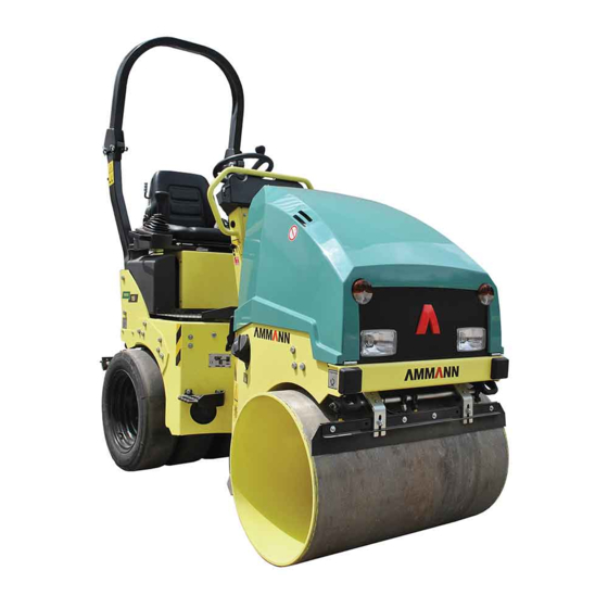
- Page 1 Original manual (EN) ARX 12 ARX 16 ARX 16 K ARX 20 Yanmar Serial No. 13000- Book ID: 1201281...
- Page 2 ARX 1...
- Page 3 Unit verification Conformity assessment as per appendix ISO 9001 certificate no.: 30605 VIII from 2000/14/EC: Recorded sound power level: 100dB(A) Noise emissions: Guaranteed sound power level: 103dB(A) Ammann Schweiz AG Manufacturer: Eisenbahnstrasse 25 Address: CH-4901 Langenthal Signatures: H. Queder Ch. Anliker...
- Page 4 ARX 1...
- Page 5 Congratulations on your purchase of an Ammann compaction roller. This quality of this compaction device is characterized by simple operation and main- tenance and is the product of many years of Ammann experience in the field of road roller engineering.
- Page 6 ARX 1...
-
Page 7: Table Of Contents
Contents General ..........13 About this manual . - Page 8 2.5.1 Disclaimer ......... . . 25 Safety information .
- Page 9 7.13 Simple/double vibration ........67 7.13.1 Vibration on / off.
- Page 10 9.10.6 Replacing the ventilation filter ......99 9.11 Emptying the water tank ....... . . 100 9.11.1 Cleaning accessories.
- Page 11 14.1 Wiring diagram, ARX 1 ........138 14.1.1 Key for ARX 1 wiring diagram .
- Page 12 ARX 1...
-
Page 13: General
1General... -
Page 14: About This Manual
About this manual This manual is part of the customer documentation for the ARX 1 vibration roller. It is customer documentation of the Ammann Schweiz AG and its representatives in other countries. 1.1.1 Target audience The target audience for this manual is the owner/operator of the ARX 4 vibration rol- ler along with his employees who have been authorized for repair, operation and maintenance by the owner/operator. -
Page 15: Validity Of The Manual
1.1.5 Storage of the manual Ammann Schweiz AG delivers every vibration roller with this manual. The manual is a permanent component of the roller. Store it so that it is always available for viewing by the users. -
Page 16: Structure Of The Manual
Only use spare parts which meet the requirements specified by the Amman Schweiz AG. These requirement are fulfilled if only original Ammann spare parts are used. For the ordering of spare parts, we provide you with a spare parts catalog. - Page 17 DANGER DANGER represents an immediate hazard leading to severe bodily injury or ● death. WARNING WARNING represents a possibly hazardous situation which could lead to se- ● vere bodily injury or to death. CAUTION CAUTION represents a possibly hazardous situation which could lead to ●...
- Page 18 ARX 1...
-
Page 19: Product Description
2Product description... -
Page 20: Identification Of The Roller
Identification of the roller 2.1.1 Machine types The data given below serve to identify the models. The machine models differ only in terms of weight and the width of the roller drum. The combined roller has a pneu- matic wheel axis instead of the smooth back drum roller. ARX 12 ARX 16 ARX 20... -
Page 21: Product Data
Product data 2.2.1 Dimensions Tab. 2-3 ARX 1 dimensions ARX 12 ARX 16 ARX 16 K ARX 20 1440 1440 1474.5 1440 1054 1000 1046 Product description... -
Page 22: Specifications
2.2.2 Specifications Tab. 2-4 ARX 1 Performance Characteristics ARX 12 ARX 16 ARX 16 K ARX 20 Service weight according to CECE 1475 1520 1460 1570 (kg) Max. service weight (kg) 1700 1700 1700 1700 Static linear load (kg/cm) Wheel load Inside turning radius (mm) 2165 2125... -
Page 23: Roller Designation
Roller designation 2.3.1 Identification plate An identification plate is affixed to the roller for identification. The identification plate is attached to the rear part of the chassis below the steering column. Fig. 2-1 Data on the identification plate Roller designation Roller model Name and address of the manufacturer Serial number... -
Page 24: Intended Use
Intended use 2.4.1 Intended purpose of the ARX 1 ARX 1 vibration rollers are universal rollers designed for use on small and medium- sized building sites. Use the ARX 1 roller exclusively for driving on and compacting: Normal modes of operation Unbonded layers (earth, gravel, crushed stone). -
Page 25: Disclaimer
Unauthorized conversions and changes to the roller are prohibited for safety reasons and void any and every Ammann guarantee as well as, possibly, the CE directive. Replaced spare or wear parts must meet the technical requirements specified by Ammann. - Page 26 ARX 1...
-
Page 27: Safety Information
3Safety information... -
Page 28: General Work Safety
General work safety The roller may only be used for driving and compacting unbound layers (gravel, ● soil) and blacktops (asphalt). Other uses are prohibited. Rollers may only be operated with all safety devices. Manipulation or disregard of ● safety devices and regulations invalidates the CE conformity. Before starting every shift, check the effectiveness of the operation and safety de- ●... -
Page 29: Shear Points
3.2.1 Shear points When closing the hood ensure that no objects are situated between the hood and ● the chassis. Take care that nothing is jammed in the joint plates when rotating the roller drums. ● Do not put hands between the roller drum and support during operation. ●... -
Page 30: Rollover Bar (Rops)
DANGER Danger to life through being thrown out! • Always wear the safety belt. Together with the rollover bar it is a safety system that can save your life. Keep the following hazards in mind: • Plane surfaces are not always uniformly load-bearing. •... -
Page 31: Noise Levels
Fig. 3-2 Never fold the ROPS down during operation WARNING Danger of accident due to alterations to the ROPS! Safety is no longer ensured if unqualified modifications or al- terations are made on the ROPS. • Do not make any modifications to the ROPS without the per- mission of the manufacturer. -
Page 32: Safety Labels On The Machine
● Replace any damaged or illegible stickers and signs immediately. ● You can order new stickers from Ammann Schweiz AG. ● From the moment the signs are no longer recognizable and understandable at first glance, the machine must be shut down until new signs are installed. - Page 33 Warning stickers Meaning Relationship to roller: Between the front and rear parts of the roller. Danger: Crushing hazard! Explanation: Only stand in this area when necessary and only with ext- reme caution! Relationship to roller: Radiator, both sides. Danger: Hand injury! Explanation: Do not put hands in the radiator fan when the machine is running.
- Page 34 Warning stickers Meaning Relationship to roller: Brake. Danger: Wear of the locking brake. Explanation: Only operate the parking brake when at a standstill. Only operate the emergency stop when at a standstill or in an emergency. After several operations of the locking brake while the roller is in motion, the brake test must be perfor- med.
-
Page 35: Notice Stickers
Warning stickers Meaning Relationship to roller: Driver’s position. Requirement: Wear a safety belt! Explanation: Always wear the safety belt when in the driver's seat. 3.5.2 Notice stickers Tab. 3-3 Notice stickers on board Notice stickers Meaning Relationship to roller: On rear chassis, front right. Designation: Guaranteed sound power level. -
Page 36: Vibration Hazard
Notice stickers Meaning Relationship to roller:On the four wheel supports. Designation: Suspension hooks. Explanation:Points on the roller at which hoisting tackle for lifting the roller can be attached. Relationship to roller:On the front and rear chassis, on the left and right, respectively. Designation: Tie-down point. - Page 37 Activity VDVx VDVy VDVz Ground compaction with vibration 0.35 0.90 0.87 Ground compaction without vibra- 1.08 0.80 0.70 tion NOTE The acceleration data are dependent on the methods used and the ground pro- perties; that is, the values may deviate from those given. Safety information...
- Page 38 ARX 1...
-
Page 39: Structure And Function
4Structure and function... -
Page 40: Component Overview
Component overview Fig. 4-1 View driver’s position Emergency stop switch Ignition switch Speed adjusting lever Operating lever Suspension Fig. 4-2 View from left Articulated joint protection Hydraulic tank oil level indicator (optical) Filler neck cover for anti-adhesive tank (option) ARX 1... - Page 41 Fig. 4-3 View from below Hydraulic oil drain Diesel tank drain Draining engine oil Draining anti-adhesive tank Fig. 4-4 View front right Identification plate Water filter Tank cap (diesel) Front sprinkler Roller drum scraper Document holder under the hood Structure and function...
- Page 42 Fig. 4-5 View rear left Water tank cover Water level display Rear sprinkler Roller drum scraper Water pump (below the footplate) Towing lugs ARX 1...
-
Page 43: Operating And Display Elements
5Operating and display elements... -
Page 44: Instrument Panel
Instrument panel 5.1.1 Switch functions Operating switch for revolving warning light (option) and work light (option) Horn Operating switch for light Operating switch for work gear / transport gear Sprinkling interval switch Indicator switch left / right (optional) Operating switch for hazard flasher (optional) Selector switch - vibration front or front and rear Operating switch for vibration automation Emergency stop... -
Page 45: Control Lamps
5.1.2 Control lamps Control lamp error Control lamp for battery charge level (charge control) Engine oil pressure control lamp Control lamp for engine coolant temperature Control lamp for hydraulic oil temperature Control lamp for emergency stop Control lamp for diesel reserve Control lamp for pre-heating Brake pressure control lamp Control lamp for parking light... -
Page 46: Control Lamp Functions
5.1.3 Control lamp functions The Error control lamp lights as soon as the controller recognizes an error. At the Error same time, an error code will be shown on the display. Check the machine based on the error code table. If, after carrying out these checks, the battery charging lamp is still lit, call a specialist. - Page 47 The Hydraulic oil temperature control lamp lights as soon as the oil temperature Hydraulic oil tem- exceeds 85°C. As soon as the temperature exceeds 95°C, error F32 appears as well. perature In this condition, the machine can only be driven at 1km/h and the vibration can no longer be switched on.
- Page 48 The Dipped lights control lamp remains lit as long as the dipped lights are switched Dipped lights The Indicator control lamp remains lit as long as the blinker is switched on. Indicators ARX 1...
-
Page 49: Error Code
Error code The current operating state and the errors recognized by the controller are displayed above the hour counter. 5.2.1 Display upon start-up If the machine is not in operation, e.g. the seat contact is not closed, the issue pre- venting start-up will be displayed: Tab. - Page 50 Display Error Effect Remedy PWM pump Vehicle standstill. Driving in direction of tra- Check magnet, wiring harness Forwards vel backwards is possible. and connector of the RC. PWM pump back- Vehicle standstill. Driving in direction of tra- Check magnet, wiring harness wards vel forwards is possible.
- Page 51 Tab. 5-3 BUS error message Display Effect Remedy No connection is present between the controller unit and the dis- Check wiring harness, display play unit. The following functions are not available: unit and controller unit. Oil temperature warning lamp. ● Brake pressure lamp.
- Page 52 ARX 1...
-
Page 53: Commissioning
6Commissioning... -
Page 54: Commissioning
Commissioning NOTE Familiarize yourself with the manual before commissioning. In order to begin operating the roller (driving), the following conditions must be ful- filled: Joint protection is opened. ● Motor is started. ● Seat contact is closed. ● Operating lever is in the neutral position. ●... -
Page 55: Operation
7Operation... -
Page 56: Rollover Bar (Rops)
Rollover bar (ROPS) DANGER Danger to life through overturning of the roller! • During operation, fold the ROPS upward. • Fold the ROPS down only for transport. 7.1.1 Folding the ROPS upward Remove the split pin. Remove the bolt. Place the parts on the rear water tank or on the seat. They should be easy to reach when you come to refit them. -
Page 57: Driver's Seat
WARNING Danger of accident due to unsecured ROPS! The ROPS can fall as soon as it crosses its center of gravity. • Never stand below the ROPS when lowering. Driver’s seat 7.2.1 Safety information DANGER Danger to life through distraction! •... -
Page 58: Adjusting The Driver's Seat
Fig. 7-2 Danger to foot of crushing 7.2.2 Adjusting the driver's seat NOTE The driver’s seat is important for your health. Adjust the seat to suit your body size. Fig. 7-3 Driver’s seat Backrest Weight Forward/backward adjustment ARX 1... -
Page 59: Protection Against Vandalism
Move the lever upward or downward. Setting Backrest The tension of the suspension can be adjusted to suit the weight of the driver. Turn the adjusting knob: Setting Weight Toward right: The spring tension of the seat will be reduced. Toward left: The spring tension of the seat will be increased. -
Page 60: Starting The Engine
Fig. 7-4 Vandalism protection cover opened / closed Starting the engine 7.4.1 Ignition switch PARK In this position you can switch on the parking light. The remaining electrical loads are off. All electrical loads are off. Ignition on All electrical consumers can be switched on. Pre-heating Start 7.4.2... -
Page 61: Driving And Braking
NOTE The control lamps for engine oil pressure, charging, hydraulic brake re- lease/supply pressure light up when the ignition is switched on. They extingu- ish once the engine is running. If the outside temperature is below 0°C: Pre-heating Turn the ignition key to position II hold it in this position for 15sec. -
Page 62: Driving
7.5.2 Driving Push the operating lever forward slowly. Driving forwards The roller moves forward. Slowly pull the operating lever into neutral position. Slowing down The roller is automatically hydrostatically braked. Pull the operating lever back slowly. Driving backward 1 The roller moves backward. Slowly pull the operating lever into the neutral position. -
Page 63: Work Gear / Transport Gear
Work gear / transport gear The roller is equipped with two gears. Turn the switch: toward the left: the hydraulic system is switched to the "transport gear" drive position. The vibration cannot be switched on now. The roller drives at a high speed. -
Page 64: Opening The Seat Switch
7.9.1 Opening the seat switch If the seat switch is opened during operation (the driver stands up), the roller will stop after a brief delay of 0.7sec. NOTE The seat switch can be opened when: • the driver leans out to the side and no longer sits on the seat with his full weight. -
Page 65: Locking Brake
The roller is now ready for operation. NOTE Release the emergency stop button by pulling upwards in the "pull-push" ver- sion. The direction arrows are missing from this button. 7.11 Locking brake The vibration roller is equipped with an automatic locking brake. The brakes for the drive motors work: When the supply pressure falls below 12 bar. -
Page 66: Switching On Continuous Sprinkling
Fig. 7-6 Water tank cover rear right 7.12.3 Switching on continuous sprinkling Turn the sprinkler switch from Pos. 0 to Pos. 1. On the instrument panel The sprinkler switches on. Press the bottom button (1). On the operating lever The sprinkler stays on as long as you are pressing the button. NOTE In the combined roller, operating lever sprinkling is used only for tire sprin- kling. -
Page 67: Simple/Double Vibration
Item 0 Interval sprinkler Item 1 7.13 Simple/double vibration WARNING Danger to life through slipping or caving in of the roller! • Do not use vibration on steep embankments or at steep angles! • Do not vibrate inside buildings and on unstable ground! NOTE Damage to material due to harsh vibration movement. -
Page 68: Manual Vibration
Vibration is not possible with the roller at a standstill. WARNING Unintentional reaction / accident hazard • If the vibration automation pre-select switch is set to automatic and vibration is activated, the roller begins to vibrate as soon as the operating lever is pushed forwards. If the driver is surprised by this reaction an uncontrolled and ha- zardous action may result. -
Page 69: Options
8Options... -
Page 70: Edge Cutter
Edge cutter DANGER Risk of injury when lowering cutting disk or pressure disk • Keep personnel out of the hazard zone when raising and lowe- ring the edge cutter. Keep to a safety distance of at least 1 m. Fig. 8-1 Edge cutter / Multifunction operating lever Raising/lowering the edge cutter Roller drum sprinkler Edge cutter water... -
Page 71: Disks
Press the "Sprinkler" (2) button. The roller drum sprinkler is switched on for Sprinkling as long as the "Sprinkler" button is pressed. Pressing the "Water" (3) button switches on the water supply for the edge cut- Water supply ter. NOTE The water supply only works if continuous roller drum sprinkling is switched Press the "Vibration"... -
Page 72: Operating Levers
WARNING Risk of injury! The disk can loosen and injure nearby persons! • Check the fastening screws when replacing the disks. Tighten the screws well on both the edge cutter and the mounting. See table 9.17, Tightening torque. 2 operating levers Fig. -
Page 73: Revolving Warning Light
to position 2: Both the rear work light and the revolving warning light are swit- ched on. NOTE If the roller is no longer fitted with a revolving warning light, only the work light is lit. Revolving warning light 8.4.1 Switching on the revolving warning light Turn the switch: to position 1: The revolving warning light is switched on. -
Page 74: Replacing The Bulb
8.4.3 Replacing the bulb Unscrew the theft-protection screw (1). Lift the cover off with a twisting motion toward the right (2). Press the two lugs of the bulb holder (3) together. Remove the bulb from the holder. Pull the bulb out of the connector. Replace the defective bulb with a new one of the same type and wattage. -
Page 75: Transport With Rops Folded Up
Loosen the wing nuts of the revolving warning light. Roof with revol- ving warning light Lift the warning light out of the holder. 8.5.3 Transport with ROPS folded up WARNING Material damage and hazard to road traffic The pressure of the head wind can cause the material to tear or come off and endanger traffic coming from behind. -
Page 76: Battery Cut-Off Switch
Battery cut-off switch The battery cut-off switch interrupts the power supply from the battery to the roller. Switch off the battery cut-off switch if the roller is not in operation for longer than two days. NOTE Always disconnect the power supply when working on the electrical system. 8.7.1 Switching battery cut-off switch on / off The battery cut-off switch is located at the rear on the battery plate. -
Page 77: Anti-Adhesive
Fig. 8-9 Removing the key Anti-adhesive Anti-adhesive is a water-soluble specialized liquid for combined rollers. The anti- adhesive ensures an effective separation between the pneumatic surfaces and the bitumen course. The anti-adhesive tank filler neck is located on the left-hand side of the driver’s posi- tion under the cover in the footplate. -
Page 78: Advantages Of Anti-Adhesive
8.8.2 Advantages of anti-adhesive No tearing of the course thanks to the good separating effect. ● Extremely low anti-adhesive consumption. ● The course can be worked at higher temperatures. ● Lower shocking to the course due to lower water consumption. ●... -
Page 79: Maintenance
9Maintenance... -
Page 80: General Safety Instructions
General safety instructions Maintenance may only be carried out by trained personnel! Only perform maintenance and repair work on the roller if it is static and secured ● from rolling away. Secure the roller with the joint protection. ● Relieve pressure before working on the hydraulic pipes. ●... - Page 81 DANGER Danger of severe injury through loose clothing being caught and drawn in! • Only open the engine hood when the engine is switched off. • If trouble shooting makes working on moving parts (engine or roller) unavoidable, never wear: necklaces, bracelets, rings, scarves, ties or other loose items of clothing.
-
Page 82: Battery Safety Instructions
9.1.1 Battery safety instructions DANGER Risk of serious injury through leaking battery acid! The sulfuric acid in the battery is poisonous and so strong it can burn holes in clothes and dissolve skin. If it gets into eyes it can lead to blindness. •... -
Page 83: Maintenance Arx 1
Maintenance ARX 1 9.3.1 Maintenance plan Chapter / D = information from dealer • • • • • • • • • • • • • • • • • • • • • • • Maintenance... - Page 84 • • • • • • • • • • • • • • • • • • • ARX 1...
- Page 85 • • • • • • • NOTE Please also observe the Yanmar engine operating instructions and the detailed instructions given there. Maintenance...
-
Page 86: Maintenance Check Sheet
Maintenance check sheet Roller, serial no.________________ Operating Comments / Date Signature hours Activity ARX 1... -
Page 87: Towing
Towing Only tow the roller in an emergency in order to move the machine away from the dan- ger zone. WARNING Risk of accident through improper towing! Adhere to the following rules: • Maximum towing speed: 1km/h • Maximum towing distance: 10m •... -
Page 88: Opening The Hood
Opening the hood DANGER Danger of severe injury through loose clothing being caught and drawn in! • Only open the engine hood when the engine is switched off. • If trouble shooting makes working on moving parts (engine or roller) unavoidable, never wear: Necklaces, bracelets, rings, scarves, ties or other loose items of clothing. -
Page 89: Engine Compartment Overview
Engine compartment overview Fig. 9-3 ARX 1 engine compartment Battery Engine oil filler neck Air-intake filter Soiling indicator for air-intake filter Oil dipstick Coolant level display Hydraulic oil filler neck Hydraulic oil filter Engine oil filter Fuel filter Coolant filler neck Water separator Maintenance... -
Page 90: Fuel (Diesel)
WARNING Risk of burning and injury when handling parts in the engine compartment! • Switch the diesel engine off when performing any inspection work. The locking brake is active when the diesel engine is switched off. Fuel (diesel) 9.8.1 Checking fuel level After the control lamp on the instrument panel lights up for the first time, the fuel in Diesel control lamp the tank will last at least ½... -
Page 91: Draining Fuel
Diesel Tab. 9-1 Excerpt from the Yanmar engine manual about diesel specifications Specifications Diesel specifications Application No. 2-D, No.1-D, ASTM D975-94 EN590:96 Europe ISO 8217 DMX International BS 2869-A1 or A2 Great Britain JIS K2204 grade no. 2 Japan KSM-2610 Korea GB252 China... -
Page 92: Cleaning The Fuel Tank
Fig. 9-5 Diesel drain 9.8.4 Cleaning the fuel tank Over time, condensation water gathers in the fuel tank. It must be drained once a year. Loosen the screw plug (1) beneath the roller using an open-ended wrench (size 27). Place a container under the drain tap. Allow about 1/2 liter of fluid to drain. -
Page 93: Water Separator Filter Element
Unscrew the filter housing (3). Remove the old filter element (1). Insert new filter element (1). Screw the filter housing (3) on. Open stop cock (2). Move to ON. 9.8.6 Water separator filter element Fig. 9-7 Water separator If there is water in the filter housing, the housing must be drained at once. Drain filter housing Close stop cock (3). -
Page 94: Engine Oil
Engine oil 9.9.1 Checking the engine oil level Check engine oil level daily using the dipstick. The dipstick (1) is located on Oil dipstick the left of the engine. Check oil level while the roller is standing on a level surface and the engine is cold. -
Page 95: Draining Engine Oil
NOTE In order to guarantee operating safety of the engine for the long term, you must not put any additives in the engine oil. 9.9.3 Draining engine oil The engine oil drain is located at the front left, between the front and rear chassis. Turn the roller all the way to the right. -
Page 96: Replace The Engine Oil Filter
9.9.4 Replace the engine oil filter Fig. 9-11 Engine oil filter Loosen the filter (1) by hand or using a filter wrench. The oil starts to flow out immediately. It’s best to place a rag under it beforehand. Replace oil filter (2). Screw the complete filter back in place. -
Page 97: Draining The Hydraulic Oil
Fig. 9-12 Hydraulic oil filler neck NOTE Observe the table of lubricants in chapter 9.15. 9.10.3 Draining the hydraulic oil NOTE Only drain the hydraulic oil at operating temperature. • The oil flows better. • Residues in the tank will be flushed out with the oil. Place a container (with at least a 30 liter capacity) under the hydraulic oil drain. -
Page 98: Cleaning The Hydraulic Oil Cooler
9.10.4 Cleaning the hydraulic oil cooler Check the cooling ribs of the hydraulic oil cooler for dirt and clogging. Clean the ribs with water or blow them out with compressed air. NOTE Never clean the cooler with high pressure (e.g. powerful water jet). Fig. -
Page 99: Replacing The Ventilation Filter
Fig. 9-16 Replacing the hydraulic oil filter, steps 4 to 6 Lightly oil the sealing ring on the filter lid. Put the filter lid in place. Tighten the lid with a torque wrench (max. torque, 20Nm). Fig. 9-17 Replacing the hydraulic oil filter, steps 7 to 8 9.10.6 Replacing the ventilation filter Fig. -
Page 100: Emptying The Water Tank
9.11 Emptying the water tank 9.11.1 Cleaning accessories Clean the following parts as required: Water tank with filler strainer ● Water filter ● Sprinkler pipes with nozzles ● 9.11.2 Emptying the water tank Unscrew the screw plug (1) of the water drain with a wrench (size 32). Drain off the water. -
Page 101: Topping Up Coolant
FULL Fig. 9-20 Expansion tank 9.12.2 Topping up coolant CAUTION Danger of scalding from hot water / steam! • Only open the tank once the engine and the coolant have cooled down. Unscrew the tank lid of the radiator. Add coolant with antifreeze until the tank is full. Fig. -
Page 102: Functional Check
Fig. 9-22 Radiator grill 9.13 Functional check 9.13.1 Sprinkler system Switch on sprinkler. Check and adjust 1 Check the nozzles on the sprinkler tubes in front and in back. 9.13.2 Roller drum scraper Tension the scrapers lightly by hand. Roller drum scra- Fig. -
Page 103: Tire Pressure
Fig. 9-24 Clearance of scraper to pneumatic wheels 9.13.3 Tire pressure Check the tire pressure on the pneumatic wheel axle. = 2-2.5bar: OK. < 2-2.5bar: Increase pressure by pumping in some air. > 2-2.5bar: Reduce pressure by letting air out. 9.13.4 Air-intake filter Press the dirt outlet of the air-intake filter at least once a week to clean it of... - Page 104 If a red ring appears on the soiling display (1) during operation of the roller, you Soiling indicator must: clean the air filter cartridge, or replace it. Fig. 9-26 Soiling indicator Check the air filter cartridge for: Air filter cartridge 1 Damage: replace the cartridge.
-
Page 105: Seat Contact And Emergency Stop
Fig. 9-28 Air intake 9.13.5 Seat contact and emergency stop Put the operating lever into the neutral position. Sit on the driver’s seat. Start the engine. The brake light (P) must extinguish at once. Brake light (P) Leave the seat. After 0.7sec., the brake light must light. - Page 106 Fig. 9-29 Remove the brake hose and seal it so that it can be pressurized. Start the roller. Press the parking brake switch. The brake light (P) must extinguish quickly. Brake light (P) Test the forwards and the backwards drive. Because the front brake remains activated, the roller does not move.
-
Page 107: Pendulum Support
9.13.7 Pendulum support Check the pendulum support once a year for excessive play. Attach the roller to a crane (central lifting point). The play can be checked by alternately applying and releasing upward pressure to the roller (visual inspection). Fig. 9-30 Pendulum support 9.13.8 Articulated joint Check the articulated joint once a year for excessive play. - Page 108 Connect the grease gun to the grease nipple. Press grease into the bearing until it visibly begins to ooze out. Put the protective cover back on. Fig. 9-32 Location of grease nipples on steering cylinder NOTE Damager to property due to increased wear! •...
-
Page 109: Lubricant Table
9.15 Lubricant table Tab. 9-2 Lubricant table Synthetic hydraulic Brand Hydraulic oil oil based on HE Grease esters ISO 2137 ISO VG 46 HVLP standard ISO 15380 HEES DIN 51502 DIN 51524 T3 Drive and vibration Drive and vibration Application hydraulics hydraulics AGIP... -
Page 110: Consumables
9.16 Consumables Tab. 9-3 Consumables Designation Brand Quantity Art.no. Engine oil Motorex Topaz 15W50 921197 Grease Motorex Moly 218 400g 1111368 Grease Motorex 174 4.5kg 1147048 Grease Blaser Foodgrease SPM00 14kg 1075038 Anti-freeze Motorex green 922341 Adhesive Loctite 4052 (blue) 50ml 1-907977 Adhesive... -
Page 111: Cleaning The Roller
Tab. 9-5 Torque: low-profile cylinder head screws and oval head screws Srew Tightening torque in SW Allen Steel quality diameter 10.9 10.9 10.9 Tab. 9-6 Torque: Shoulder screws Srew Tightening torque in SW Allen Steel quality diameter 12.9 Tab. 9-7 Torque: Countersunk head screws Srew Tightening torque in SW Allen... - Page 112 DANGER Danger to life through runaway roller. Persons standing in the vicinity can be rolled over! • Before cleaning the roller, be absolutely certain to secure it against unintentional rolling away. NOTE While cleaning, observe the following: • Do not use aggressive or flammable cleansing agents (e.g. gasoline or in- flammable substances).
-
Page 113: Repair
10Repair... -
Page 114: Battery
10.1 Battery NOTE Risk of cable fire or short circuit. Keep to the proper sequence when removing or installing the terminal connec- tions. The battery charge level can be read in the multifunction display unit. Ignition on = battery voltage. The battery voltage should not fall below 10 volts ●... -
Page 115: Starting With Another Battery (Jumpering)
Fig. 10-2 Replacing the battery NOTE The battery poles and terminals must be clean. If they are coated with a (whitish or greenish) sulfur crust they must be cleaned. 10.1.2 Starting with another battery (jumpering) Connect the red cable to the (+) terminals of both batteries. Connect one end of the green or black cable to the (-) terminals of both batte- ries. -
Page 116: Charging The Battery Using A Battery Charger
NOTE The battery poles and terminals must be clean. If they are coated with a (whitish or greenish) sulfur crust they must be removed and cleaned. 10.1.3 Charging the battery using a battery charger Disconnect the battery. Connect the battery charger. Observe the battery charger manufacturer’s manual. -
Page 117: Engine Compartment Fuses
10.2.1 Engine compartment fuses The fuses are located on the right of the engine, at the front between the engine and the water tank. The fuse numbers are indicated on the fuse box. Always replace a defective fuse (1) with a functioning fuse (2) of the same amperage (according to the label or color of the fuse). -
Page 118: Replacing Bulbs
Fuse No. Power Fuse-protected circuit 10 A Seat heating Controller 10 A Controller, drive pump, brake valve, holding solenoid 15 A Sprinkling 10 A Flow divider, edge cutter 10 A Vibro switch valve Brake pressure switch 25 A Fuse, hydraulic oil cooler 15 A Reserve Fig. - Page 119 Fig. 10-6 Dipped lights and parking lights: Remove the plug from the rear of the lamp unit. Dipped light Remove the guard. Press on the end of the securing clip to remove it. Replace the defective bulb with a new one of the same type and power. Put the guard back on the casing.
-
Page 120: Replacing Bulbs At The Rear
10.3.2 Replacing bulbs at the rear At the rear, you have direct access to the work light (1) and the tail lights (2). Fig. 10-8 Work light / tail light Remove the entire work light from the water tank. Work light Remove the plug from the rear of the lamp unit. -
Page 121: Replacing Gas Struts
10.4.1 Replacing gas struts WARNING Risk of accident through hood falling down! • Secure the hood before you replace the gas struts. Support the hood with a rod. ○ Attach the hood to a crane by the handle. ○ Use a screwdriver to lift the clips. removal Pull the gas strut away from the ball joint. - Page 122 ARX 1...
-
Page 123: Storage
11Storage... -
Page 124: Storage
11.1 Storage 11.1.1 Short-term storage Put the operating lever into neutral position. ● Secure the roller from unauthorized start-up and unintentional rolling away. ● Remove the ignition key. ● 11.1.2 Long-term storage Tab. 11-1 Long-term storage defective compo- precautions Chapter nents Diesel engine Observe the information in the “Long-term storage”... -
Page 125: Draining The Water Tank And Sprinkler
11.2.1 Draining the water tank and sprinkler The water tank and the sprinkler unit must be drained. Undo the quick-release coupling of the sprinkler hose. Press the black plastic ring against the screw connection. Pull the hose off the coupling. Drain off the water. - Page 126 ARX 1...
-
Page 127: Transport
12Transport... -
Page 128: Transport
12.1 Transport DANGER Risk of crushing through presence in the pivoting area (dan- ger zone)! • The articulated joint lock (joint protection) must be fitted before lifting the roller for transport. 12.1.1 Joint protection Release the lower part of the joint protection (1). Blocking the joint protec- First, remove the compression spring (2) and then the lock bolt (3). -
Page 129: Lifting At The 1-Point Lifting Eye
12.1.2 Lifting at the 1-point lifting eye Bring the joint protection into place. Lift the roller vertically with suitable hoisting tackle. Use suitable hoisting tackle having the same length as the ARX. 1. The 1-point lifting eye is designed for a WLL of 1.7 tons (Working Load Limit). Fig. -
Page 130: Center Of Gravity
Fig. 12-3 Lashing the roller / side view Fig. 12-4 Lashing the roller / front view CAUTION Risk of accident through blocked steering! • Open the joint protection before starting the roller. 12.1.4 Center of gravity The center of gravity relevant to transport is located 670mm from the floor and approx. - Page 131 Fig. 12-5 Roller's center of gravity Transport...
- Page 132 ARX 1...
-
Page 133: Disposal
13Disposal... -
Page 134: Introduction
13.1 Introduction CAUTION Environmental hazard through operating materials! • Do not allow any liquids get into drains, soil or the environment. The roller must be disposed of properly; ask your authorized dealer. 13.2 Removal and depressurization of the gas struts WARNING Eye injury! Because of the high internal pressure, chips and oil can spat-... - Page 135 1. Saw cut / drilled hole 2. Saw cut / drilled hole about Pressurized Bottom Piston rod tube Fig. 13-1 Removal and depressurization of the gas struts 1. saw cut / hole position: Cut or drill into the pressurized tube about 20mm from the bottom.
- Page 136 ARX 1...
-
Page 137: Appendix
14Appendix... -
Page 138: Wiring Diagram, Arx 1
14.1 Wiring diagram, ARX 1 Fig. 14-1 Wiring diagram no. 1202835-1 ARX 1... - Page 139 Fig. 14-2 Wiring diagram no. 1202835-2 Appendix...
-
Page 140: Key For Arx 1 Wiring Diagram
14.1.1 Key for ARX 1 wiring diagram Element Description Diesel tank fuel level display Voltage display Horn Reversing alarm Warning buzzer, flow divider Warning buzzer, seat contact delay Front right low beam light Front left low beam light Front right parking light Front right position light Front left parking light Front left position light... - Page 141 Element Description Fuse, controller, inputs Fuse, hydraulic oil cooler Fuse, reserve Fuse, starter Fuse, diesel pump Fuse, reserve Fuse, reserve Alternator Battery Warning lamp, error Control lamp, charging control Warning lamp - engine oil pressure Warning lamp - coolant temperature Warning lamp, hydraulic oil temperature Warning lamp, emergency stop Warning lamp, diesel reserve...
- Page 142 Element Description Starter motor Hydraulic oil cooler Diesel pump Sprinkler pump Sprinkler pump, anti-adhesive Controller Display unit Measuring transducer, asphalt temperature Operating hours counter Pre-heating coil Seat heating Switch, ignition Switch, emergency stop Operating lever sensor, right Operating lever switch, right Potentiometer, sprinkler Switch, work gear Switch, vibration automation...
- Page 143 Element Description Sensor, hydraulic oil temperature Sensor, diesel tank Sensor, engine oil pressure Sensor, coolant temperature Free-running diode, buzzer, flow divider Free-running diode, edge cutter 1 Free-running diode, edge cutter 2 Pull-in / holding solenoid Valve, locking brake Drive pump, forwards Drive pump, backwards Valve, front vibration Valve, rear vibration...
-
Page 144: Hydraulics Diagram, Arx 1
14.2 Hydraulics diagram, ARX 1 Fig. 14-3 Hydraulics diagram no. 1193831 ARX 1... -
Page 145: Key For Arx 1 Hydraulics Diagram
14.2.1 Key for ARX 1 hydraulics diagram Element Description Drive pump Vibro-steering pump Front drive motor Rear drive motor Steering orbitrol Steering cylinder Vibro switch valve Vibro motor, front Vibro motor, rear Oil cooler Return-line suction filter Hydraulic oil tank Filler, ventilation filter Brake valve Flow divider... -
Page 146: Hydraulics Diagram, Arx 1 K
14.3 Hydraulics diagram, ARX 1 K Fig. 14-4 Hydraulics diagram no. 1193830 ARX 1... -
Page 147: Key For Arx 1 K Hydraulics Diagram
14.3.1 Key for ARX 1 K hydraulics diagram Element Description Drive pump Vibro-steering pump Front drive motor Rear drive motor Steering orbitrol Steering cylinder Vibro switch valve Vibro motor, front Vibro motor, rear Oil cooler Return-line suction filter Hydraulic oil tank Filler, ventilation filter Brake valve Drive motor, rear left... - Page 148 ARX 1...
- Page 149 Tables Documents for the ARX 1 ............14 Roller with roller drum .
- Page 150 Excerpt from the Yanmar engine manual about diesel specifications..... 91 Lubricant table............. . 109 Consumables .
Need help?
Do you have a question about the ARX 16 K Yanmar and is the answer not in the manual?
Questions and answers