Table of Contents
Advertisement
Available languages
Available languages
Quick Links
Installations- und Betriebsanleitung
BY
Servicehandbuch
Modell: Q(D)X, Q(D), Q(D)Y
Vor der Inbetriebnahme sicherstellen, dass die Pumpe geerdet ist.
Prüfen, ob der Fehlerstromschutzschalter ordnungsgemäß angebracht ist.
Warnung
Die elektrische Pumpe nicht berühren, während sie in Betrieb ist.
Die elektrische Pumpe nicht ohne Wasser betreiben.
Advertisement
Chapters
Table of Contents

Related Manuals for WITA Adelino QX


Summary of Contents for WITA Adelino QX
- Page 1 Installations- und Betriebsanleitung Servicehandbuch Modell: Q(D)X, Q(D), Q(D)Y Vor der Inbetriebnahme sicherstellen, dass die Pumpe geerdet ist. Prüfen, ob der Fehlerstromschutzschalter ordnungsgemäß angebracht ist. Warnung Die elektrische Pumpe nicht berühren, während sie in Betrieb ist. Die elektrische Pumpe nicht ohne Wasser betreiben.
- Page 2 EG-Konformitätserklärung Name des Ausstellers: WITA Sp. z o. o. 86-005 Białe Błota Zielonka, ul. Biznesowa 22 Polen Gegenstand der Erklärung Adelino-Tauchpumpe Design: QDX...L2, QX...L2, QDX...K3, QX...K3, QDX...T2, QX...T2, QD...J, Q...J, Q...L1, QY...Z4, QY...Z3, QY...Z2, QY...Z1, QY...L3, QY...L2, QY...L1, QDY...K2, QY...K2, QY...K1 Wir erklären in alleiniger Verantwortung, dass die oben angegebenen Produkte, auf die sich...
-
Page 3: Table Of Contents
Inhalt 1. Produktinformationen • • • • • • • • • • • • • • • • • • • • • • • • • • • • • • • • • • • • • • • • • • • • • • • • • • 2. - Page 4 Vielen Dank, dass Sie sich für unser Produkt entschieden haben. Lesen Sie sich diese Anleitung vor der Installation und Verwendung bitte aufmerksam durch und bewahren Sie sie sorgfältig auf. Bei Installation und Betrieb müssen die örtlichen Bestimmungen eingehalten werden. Unsachgemäße Verwendung kann zu Personenschäden führen. •...
- Page 5 Weist darauf hin, dass Berühren verboten ist, und Nichtbeachtung zum Tod oder zu schweren Verletzungen führt Weist darauf hin, dass die entsprechenden Vorschriften eingehalten werden müssen Weist auf verbotene Handlungen hin, die nicht ausgeführt werden dürfen oder beendet werden müssen Weist auf das Symbol des Schutzleiters zum Schutz vor Stromschlag hin Erklärung Gefahren oder Schäden, die durch eine der nachfolgend aufgeführten Umstände infolge von...
-
Page 6: Produktinformationen
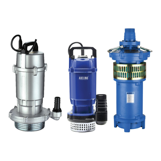
1. Produktinformationen 1.1 Anwendungen der Pumpe Die elektrischen Pumpen der Serien Q(D)X, Q(D), Q(D)Y-K und QY sind elektrische Tauchpumpen (hier als „elektrische Pumpen“ bezeichnet). Mit ihrer großen Förderhöhe und vielfältigen Anwendungsmöglichkeiten aufgrund der mehrstufigen Laufradkonstruktion ist diese Serie optimal geeignet für Wasserförderungsanlagen in den Bereichen landwirtschaftliche Bewässerung und Entwässerung, Beregnung, Parkberegnung, Brunnenwasserförderung, Wasserversorgung für Hochhäuser und Wasserversorgung und Entwässerung in der Viehzucht. - Page 7 1.5 Anschlussplan der Pumpe In den folgenden Abbildungen wird die grundsätzliche Verkabelung der einphasigen und der dreiphasigen elektrischen Pumpen dargestellt. U V W Schwim- merschalter Kondensator Einphasig Dreiphasig Bei der Verdrahtung der elektrischen Pumpe muss ein Fehlerstromschutzschalter installiert werden und der gelb-grüne Draht mit Erdungskennzeichnung im abgehenden Kabel muss sicher geerdet werden.
-
Page 8: Technische Daten
2. Technische Daten Die folgende Tabelle enthält die technischen Daten der elektrischen Pumpen der Serien Q(D)X, Q(D), Q(D)Y-K und QY. Max. Max. Spannung Strom Leistung Förderhöhenbereich Auslauf Durchfluss Förderhöhe Modell (kW) (mm) (m³/h) QDX1.5-12-0.25L2 0,25 5–13 QDX1.5-17-0.37L2 0,37 4–18 QDX1.5-25-0.55L2 0,55 17–26 QDX3-18-0.55L2... - Page 9 Max. Max. Spannung Strom Leistung Förderhöhenbereich Auslauf Durchfluss Förderhöhe Modell (kW) (mm) (m³/h) QX3-24-0.75K3 0,75 14–26 QX8-18-0.75K3 0,75 15–19 QX10-16-0.75K3 0,75 10–19 QX30-6-0.75K3 0,75 2–8 QX3-30-1.1K3 18–32 QX6-25-1.1K3 8–29 3 × 400 V, QX14-16-1.1K3 9–17 50 Hz 2-polig QX15-14-1.1K3 9–17 QX40-7-1.1K3 3–9 QX15-18-1.5K3...
- Page 10 Max. Max. Leistung Förderhöhenbereich Auslauf Modell Spannung (V) Strom (A) Fördermenge Förderhöhe (kW) (mm) (m³/h) Q3-60/4-1.5J 0–66 Q6-35/2-1.5J 20–40 Q10-26/2-1.5J 0–30 Q10-32/3-1.5J 20–39 Q10-32/3-1.5P 20–39 Q15-20/2-1.5J 0–28 Q3-85/5-1.8J 50–88 3 × 400 V, 50 Hz 2-polig Q12-36/3-1.8J 10–40 Q12-36/3-1.8P 10–40 Q3-98/6-2.2J 55–105 Q10-40/3-2.2J...
- Page 11 Max. Max. Spannung Strom Leistung Förderhöhenbereich Auslauf Durchfluss Förderhöhe Modell (mm) (kW) (m³/h) QY40-28-5.5L1 11,1 19–34 QY65-18-5.5L2 11,1 0–19 QY100-13-5.5L1 11,1 0–19 QY10-110/4-7.5L1 14,9 84–115 QY15-95/4-7.5L1 14,9 80–98 QY18-84/4-7.5L1 14,9 70–88 QY25-60/2-7.5L1 14,9 45–66 QY40-38-7.5L1 14,9 28–44 QY50-30-7.5L1 14,9 0–32 QY65-25-7.5L2 14,9 0–26...
- Page 12 Max. Max. Leistung Förderhöhenbereich Auslauf Modell Spannung (V) Strom (A) Fördermenge Förderhöhe (kW) (mm) (m³/h) QY3-55/4-1.5K2 5–65 QY10-30/3-1.5K2 10–34 QY15-21/3-1.5K2 10–36 QY3-82/5-1.8K2 30–88 QY10-40/4-1.8K2 5–50 3 × 400 V, 50 Hz 2-polig QY12-36/4-1.8K2 5–50 QY3-96/6-2.2K2 30–104 QY15-35/4-2.2K2 5–48 QY3-112/7-3K2 30–120 QY20-36/2-3K1 30–40...
-
Page 13: Installationsanleitung
3. Installationsanleitung 3.1 Maßnahmen vor der Installation 1. Die elektrische Pumpe vor der Installation und Verwendung vollständig auf Transport- oder Lagerungsschäden überprüfen, z. B. sicherstellen, dass sich Kabel in einwandfreiem Zustand befinden. Wird ein Schaden festgestellt, ist das betreffende Teil von einer Fachkraft auszutauschen oder zu reparieren. - Page 14 2. Die maximale Eintauchtiefe der elektrischen Pumpe im Wasser beträgt 5 m und der Abstand vom Grund muss mindestens 0,5 m betragen. Die elektrische Pumpe darf nicht in Schlamm getaucht werden und das Laufrad darf nicht durch Wasserpflanzen oder Fremdkörper blockiert werden, da dies die Funktion der Pumpe beeinträchtigen würde.
- Page 15 Tabelle 2: Kabelanschlussschema Schema Beschreibung 1. Isolierungsschicht entfernen, ohne den Leiter zu beschädigen. 2. Lange und kurze Kabel gestaffelt anordnen. 3. Sicherstellen, dass die Verbindung frei von Öl, Wasser und anderen Verunreinigungen ist. 1. Jeden Leiter gleichmäßig in mehrere Stränge aufteilen (mindestens 6 Stk.) und straffen.
-
Page 16: Instandhaltung
4. Instandhaltung 1. Den Isolationswiderstand zwischen Gehäuse und Wicklung der elektrischen Pumpe regelmäßig kontrollieren. Er muss mindestens 1 MΩ betragen, wenn die Betriebstemperatur nahezu erreicht ist. Andernfalls muss der Betrieb der Pumpe unterbrochen werden, bis die entsprechenden Wartungsmaßnahmen durchgeführt wurden und die geltenden Anforderungen erfüllt sind. -
Page 17: Problemlösung
5. Problemlösung Vor der Durchführung von Maßnahmen zur Problemlösung sicherstellen, dass die Pumpe ausgeschaltet ist und alle beweglichen Teile stillstehen. Pumpe gegen versehentliches Wiedereinschalten sichern. Störung Ursache Behebung 1. Die Versorgungsspannung ist zu niedrig. 1. Spannung auf ±10 % des Nennwerts einstellen 2. -
Page 18: Anhang
Anhang 7. Anhang Entwässerungstauchpumpe Q(D)X-L US GPM Imp GPM Feet Fuß QDX-L n = 2850 U/min Förderstrom (l/min) Förderstrom (I/min) Förderstrom (m³/h) Förderstrom (m3/h) US GPM Imp GPM P (kPa) H (m) Feet Fuß QDX-L n = 2850 U/min Förderstrom (l/min) Förderstrom (I/min) Förderstrom (m3/h) Förderstrom (m³/h) - Page 19 Anhang H (m) QDX-K3 3-30-1.1 3-24-0.75 3-18-0.55 6-25-1.1 Förderstrom (I/min) Förderstrom (m³/h) H (m) QDX-K3 8-18-0.75 14-16-1.1 15-14-1.1 25-12-1.5 15-10-0.75 Förderstrom (I/min) Förderstrom (m³/h) H (m) QDX-K3 15-18-1.5 10-16-0.75 10-12-0.55 15-7-0.55 Förderstrom (I/min) Förderstrom (m³/h) H (m) QDX-K3 50-7-1.5 30-6-0.75 40-6-1.1 40-9-1.5 Förderstrom (I/min)
- Page 20 Anhang Entwässerungstauchpumpe Q(D)X-T US GPM P (kPa) Imp GPM Feet Fuß QDX-T n = 2850 U/min Förderstrom (l/min) Förderstrom (I/min) Förderstrom (m3/h) Förderstrom (m³/h) US GPM P (kPa) Imp GPM Feet Fuß QDX-T n = 2850 U/min Förderstrom (l/min) Förderstrom (I/min) Förderstrom (m3/h) Förderstrom (m³/h) US GPM...
- Page 21 Anhang Mehrstufige Tauchpumpe Q(D) US GPM Imp GPM P (kPa) Feet Fuß n = 2850 U/min Förderstrom (l/min) Förderstrom (I/min) Förderstrom (m3/h) Förderstrom (m³/h) US GPM P (kPa) Imp GPM Feet Fuß n = 2850 U/min Förderstrom (l/min) Förderstrom (I/min) Förderstrom (m3/h) Förderstrom (m³/h) US GPM...
- Page 22 Anhang Tauchpumpe QY US GPM Imp GPM P (kPa) Feet Fuß n = 2850 U/min n = 2850 U/min Förderstrom (l/min) Förderstrom (I/min) Förderstrom (m3/h) Förderstrom (m³/h) US GPM Imp GPM P (kPa) Feet Fuß n = 2850 U/min Förderstrom (m3/h) Förderstrom (l/min) US GPM Imp GPM...
- Page 23 Anhang US GPM P (kPa) Imp GPM Feet Fuß n = 2850 U/min Förderstrom (l/min) Förderstrom (I/min) Förderstrom (m3/h) Förderstrom (m³/h) US GPM Imp GPM P (kPa) Feet Fuß n = 2850 U/min Förderstrom (l/min) Förderstrom (I/min) Förderstrom (m³/h) Förderstrom (m3/h) US GPM Imp GPM P (kPa)
- Page 24 Anhang US GPM P (kPa) Imp GPM Feet Fuß n = 2850 U/min Förderstrom (l/min) Förderstrom (I/min) Förderstrom (m³/h) Förderstrom (m3/h) US GPM Imp GPM P (kPa) Feet Fuß n = 2850 U/min Förderstrom (l/min) Förderstrom (I/min) Förderstrom (m3/h) Förderstrom (m³/h) Mehrstufige Tauchpumpe Q(D)Y-K2 US GPM Imp GPM...
- Page 25 Förderstrom (I/min) Förderstrom (m³/h) Anhang US GPM Imp GPM Feet Fuß QDY-K2 n = 2850 U/min Förderstrom (l/min) Förderstrom (I/min) Förderstrom (m³/h) Förderstrom (m3/h)
- Page 27 Installation and operation instructions Service Manual Model: Q(D)X, Q(D), Q(D)Y Make sure the electric pump is grounded before operation Check if leakage protection device is reliably equipped Warning Do not touch the electric pump while it is running Do not run electric pump without water...
- Page 28 EC Declaration of Conformity Name of the issuer: WITA Sp. z o. o. 86-005 Białe Błota Zielonka, ul. Biznesowa 22 Poland Subject of the declaration Adelino Submersible Pump Design: QDX...L2, QX...L2, QDX...K3, QX...K3, QDX...T2, QX...T2, QD...J, Q...J, Q...L1, QY...Z4, QY...Z3, QY...Z2, QY...Z1, QY...L3, QY...L2, QY...L1, QDY...K2, QY...K2, QY...K1...
- Page 29 Contents 1. Product Information • • • • • • • • • • • • • • • • • • • • • • • • • • • • • • • • • • • • • • • • • • • • • • • • • • • • • 2.
- Page 30 Thank you very much for choosing our product. Please read through this instruction manual and keep it properly before installation and use. Installation and operation muss comply with local regulations. Improper use may lead to personal injuries. • Before operation, make sure that the electric pump is grounded reliably and leakage protection device is equipped •...
- Page 31 Indicates that touch is prohibited, which, if ignored, will result in death or serious personal injury Indicates that the relevant rules shall be observed Indicates prohibited actions, which must not be taken or must be stopped Indicates the symbol of ground wire in case of an electric shock Statement: Any hazard or loss caused by any of the following circumstances, where the content hereof is not observed, is not included in the scope of the manufacturer’s quality warranty:...
-
Page 32: Product Information
1. Product Information 1.1 Pump Applications Submersible electric pumps (hereinafter referred to as the “electric pumps”) include Q(D)X, Q(D), Q(D)Y-K, and QY electric pumps. With high lift and widespread applicability owing to the adoption of multi-stage impeller structure, this series of electric pumps are essential water delivery equipment in such applications as farmland irrigation and drainage, spray irrigation, landscape spray irrigation, well water lifting, water supply for tower, and water supply &... - Page 33 1.5 Pump Wiring Diagramm The following two figures describe the general wiring of the single phase and three phase electric pumps. U V W Float switch Capacitor Single phase Three phase At wiring, electric pumps should be correctly installed with electrical leakage protector, and a yellow-green wire attached with earthing mark in the outgoing cable of electric pump shall be earthed reliably.
-
Page 34: Technical Parameters
2. Technical Parameter The following table describes the technical data of the electric pumps of Q(D)X, Q(D), Q(D)Y-K, and QY series. Head Voltage Current Power Max. Flow Max.Head Discharge Model Range (mm) (kW) (m³/h) QDX1.5-12-0.25L2 0.25 5~13 QDX1.5-17-0.37L2 0.37 4~18 QDX1.5-25-0.55L2 0.55 17~26... - Page 35 Head Voltage Current Power Max. Flow Max.Head Discharge Model Range (kW) (m³/h) (mm) QX3-24-0.75K3 0.75 14~26 QX8-18-0.75K3 0.75 15~19 QX10-16-0.75K3 0.75 10~19 QX30-6-0.75K3 0.75 QX3-30-1.1K3 18~32 QX6-25-1.1K3 8~29 3 × 400V, 50Hz QX14-16-1.1K3 9~17 2 Pole QX15-14-1.1K3 9~17 QX40-7-1.1K3 QX15-18-1.5K3 8~19 QX25-12-1.5K3 5~15...
- Page 36 Head Voltage Current Power Max. Flow Max.Head Discharge Model Range (kW) (m³/h) (mm) Q3-60/4-1.5J 0~66 Q6-35/2-1.5J 20~40 Q10-26/2-1.5J 0~30 Q10-32/3-1.5J 20~39 Q10-32/3-1.5P 20~39 Q15-20/2-1.5J 0~28 Q3-85/5-1.8J 50~88 3 × 400V, 50Hz 2 Pole Q12-36/3-1.8J 10~40 Q12-36/3-1.8P 10~40 Q3-98/6-2.2J 55~105 Q10-40/3-2.2J 0~43 Q3-116/7-3J 60~125...
- Page 37 Head Voltage Current Power Max. Flow Max.Head Discharge Model Range (kW) (m³/h) (mm) QY40-28-5.5L1 11.1 19~34 QY65-18-5.5L2 11.1 0~19 QY100-13-5.5L1 11.1 0~19 QY10-110/4-7.5L1 14.9 84~115 QY15-95/4-7.5L1 14.9 80~98 QY18-84/4-7.5L1 14.9 70~88 QY25-60/2-7.5L1 14.9 45~66 QY40-38-7.5L1 14.9 28~44 QY50-30-7.5L1 14.9 0~32 QY65-25-7.5L2 14.9 0~26...
- Page 38 Head Voltage Current Power Max. Flow Max.Head Discharge Model Range (kW) (m³/h) (mm) QY3-55/4-1.5K2 5~65 QY10-30/3-1.5K2 10~34 QY15-21/3-1.5K2 10~36 QY3-82/5-1.8K2 30~88 QY10-40/4-1.8K2 5~50 3 × 400V, 50Hz 2 Pole QY12-36/4-1.8K2 5~50 QY3-96/6-2.2K2 30~104 QY15-35/4-2.2K2 5~48 QY3-112/7-3K2 30~120 QY20-36/2-3K1 30~40...
-
Page 39: Installation Instructions
3. Installation Instructions 3.1 Before Installation 1. Electric pumps shall be comprehensively checked for damage during transportation and storage prior to installation and use, e.g. whether cable is in good condition. In case of any damage, please have the replacement or repair carried out by a specialist. - Page 40 2. When electric pump is immersed in the water, the depth shall not exceed 5m, and it shall be more than 0.5m above the water bottom. Electric pump shall not immerse into mud, and the impeller shall be prevented from being blocked or jammed by water plants or debris, resulting in malfunction of the electric pump.
- Page 41 Table 2: Cable wiring diagram Pos. Schematic diagram Description 1. Remove the insulating layer without damaging the conductor. 2. Stagger long and short wires. 3. Ensure that no oil, water or any other pollutant exists at the connection. 1. Divide each connector into several strands evenly (no less than 6 Shock hazard, no man ones) and tighten them or animal shall enter...
- Page 42 4. Maintance 1. Regularly inspect the insulation resistance between the enclosure and the winding of the electric pump, which shall not be less than 1MΩ when the operating temperature is nearly achieved. Otherwise, the use of the pump shall not be allowed until the corresponding maintenance measures are taken and the relevant requirements are met.
-
Page 43: Troubleshooting
5. Troubleshooting Before performing any troubleshooting, make sure the pump has been turned off and all moving components have stopped rotating. Make sure that the pump cannot be turned on accidentally. Fault Cause Remedy 1. Adjust the voltage to ±10% of the rated value 1. -
Page 44: Appendix
Appendix 7. Appendix Q(D)X-L Submersible Drainage Pump Q(D)X-K3 Submersible Drainage Pump H(m) Q( m³/h) Q(l/min) - Page 45 Appendix H(m) Q( m³/h) Q(l/min) H(m) Q( m³/h) Q(l/min) H(m) Q( m³/h) Q(l/min) H(m) Q( m³/h) Q(l/min)
- Page 46 Appendix Q(D)X-T Submersible Drainage Pump...
- Page 47 Appendix Q(D) Multistage Submersible Pump...
- Page 48 Appendix QY Submersible Pump...
- Page 49 Appendix...
- Page 50 Appendix Q(D)Y-K2 Multistage Submersible Pump...
- Page 51 Appendix...
- Page 53 Instrukcja montażu i obsługi Instrukcja obsługi Modele: Q(D)X, Q(D), Q(D)Y Przed rozpoczęciem eksploatacji upewnić się, czy pompa elektryczna jest uziemiona. Ostrzeżenie Sprawdzić, czy zabezpieczenie upływowe zostało należycie zamontowane. Nie dotykać pompy elektrycznej w trakcie pracy. Nie uruchamiać pompy elektrycznej bez wody.
- Page 54 Deklaracja zgodności CE Dystrybutor: WITA Sp. z o.o. 86-005 Białe Błota Zielonka, ul. Biznesowa 22 Polska Przedmiot deklaracji: Pompa zanurzeniowa Adelino Model: QDX...L2, QX...L2, QDX...K3, QX...K3, QDX...T2, QX...T2, QD...J, Q...J, Q...L1, QY...Z4, QY...Z3, QY...Z2, QY...Z1, QY...L3, QY...L2, QY...L1, QDY...K2, QY...K2, QY...K1 Z pełną...
- Page 55 Spis treści 1. Informacje o produkcie • • • • • • • • • • • • • • • • • • • • • • • • • • • • • • • • • • • • • • • • • • • • • • • • • • • 2.
- Page 56 Dziękujemy za wybranie naszego produktu. Prosimy o przeczytanie niniejszej instrukcji i zachowanie jej na czas montażu i użytkowania. Montaż i obsługa muszą być przeprowadzone zgodne z niniejszą instrukcją oraz lokalnymi przepisami. Niewłaściwe użytkowanie może doprowadzić do obrażeń ciała. Przed rozpoczęciem eksploatacji należy upewnić się, czy pompa elektryczna jest prawidłowo uziemiona i czy zamontowano zabezpieczenie upływowe •...
- Page 57 Symbol ten oznacza, że obowiązuje zakaz dotykania, a jego złamanie prowadzi do śmierci lub poważnych uszkodzeń ciała. Symbol ten oznacza, że należy przestrzegać oznaczonych nim zasad. Symbol ten oznacza czynności zabronione, których nie wolno podejmować i które należy powstrzymywać. Symbol ten oznacza przewód uziemiający – na wypadek porażenia prądem elektrycznym.
- Page 58 1. Informacje o produkcie 1.1 Zastosowania pompy Elektryczne pompy zanurzeniowe obejmują modele Q(D)X, Q(D), Q(D)Y-K, i QY. Dzięki dużej wysokości podnoszenia i wszechstronnemu zastosowaniu dzięki wielostopniowej konstrukcji z wirnikiem, prezentowana seria pomp stanowi głównie sprzęt doprowadzający wodę w takich zastosowaniach jak nawadnianie i odwadnianie pól uprawnych, nawadnianie natryskowe dla architektury krajobrazu, pompowanie wody ze studni, doprowadzanie wody do wież...
- Page 59 1.5 Schemat instalacji elektrycznej pompy Następujące rysunki przedstawiają szczegóły wewnętrznej instalacji elektrycznej pomp elektrycznych. U V W Wył. Float pływakowy switch Kondensator Capacitor 1 faza 3 fazy W pompach elektrycznych należy odpowiednio zamontować zabezpieczenie upływowe. Wymagane jest również właściwe uziemienie podłączonego żółto-zielonego przewodu z oznaczeniem uziemienia w przewodzie wyjściowym pompy elektrycznej.
- Page 60 2. Parametry techniczne Następująca tabela przedstawia dane techniczne dotyczące pomp elektrycznych z serii Q(D)X, Q(D), Q(D)Y-K i QY Maks. Średnica Zakres Napięcie Natężenie Maks. pompowania Model przepływ podnoszenie przyłącza (kW) (m³/h) (mm) QDX1.5-12-0.25L2 0.25 5~13 QDX1.5-17-0.37L2 0.37 4~18 QDX1.5-25-0.55L2 0.55 17~26 QDX3-18-0.55L2 0.55...
- Page 61 Maks. Maks. Zakres Średnica Napięcie Natężenie Model przepływ podnoszenie pompowania przyłącza (kW) (m³/h) (mm) QX3-24-0.75K3 0.75 14~26 QX8-18-0.75K3 0.75 15~19 QX10-16-0.75K3 0.75 10~19 QX30-6-0.75K3 0.75 QX3-30-1.1K3 18~32 QX6-25-1.1K3 8~29 3 × 400V, 50Hz QX14-16-1.1K3 9~17 2-biegunowe QX15-14-1.1K3 9~17 QX40-7-1.1K3 QX15-18-1.5K3 8~19 QX25-12-1.5K3 5~15...
- Page 62 Maks. Maks. Zakres Średnica Napięcie Natężenie Model przepływ podnoszenie pompowania przyłącza (kW) (m³/h) (mm) Q3-60/4-1.5J 0~66 Q6-35/2-1.5J 20~40 Q10-26/2-1.5J 0~30 Q10-32/3-1.5J 20~39 Q10-32/3-1.5P 20~39 Q15-20/2-1.5J 0~28 Q3-85/5-1.8J 50~88 3 × 400V, 50Hz 2-biegunowe Q12-36/3-1.8J 10~40 Q12-36/3-1.8P 10~40 Q3-98/6-2.2J 55~105 Q10-40/3-2.2J 0~43 Q3-116/7-3J 60~125...
- Page 63 Maks. Maks. Zakres Średnica Napięcie Natężenie Model przepływ podnoszenie pompowania przyłącza (kW) (m³/h) (mm) QY40-28-5.5L1 11.1 19~34 QY65-18-5.5L2 11.1 0~19 QY100-13-5.5L1 11.1 0~19 QY10-110/4-7.5L1 14.9 84~115 QY15-95/4-7.5L1 14.9 80~98 QY18-84/4-7.5L1 14.9 70~88 QY25-60/2-7.5L1 14.9 45~66 QY40-38-7.5L1 14.9 28~44 QY50-30-7.5L1 14.9 0~32 QY65-25-7.5L2 14.9...
- Page 64 Maks. Maks. Zakres Średnica Napięcie Natężenie Model przepływ podnoszenie pompowania przyłącza (kW) (m³/h) (mm) QY3-55/4-1.5K2 5~65 QY10-30/3-1.5K2 10~34 QY15-21/3-1.5K2 10~36 QY3-82/5-1.8K2 30~88 QY10-40/4-1.8K2 5~50 3 × 400V, 50Hz 2 Pole QY12-36/4-1.8K2 5~50 QY3-96/6-2.2K2 30~104 QY15-35/4-2.2K2 5~48 QY3-112/7-3K2 30~120 QY20-36/2-3K1 30~40...
- Page 65 3. Instrukcje montażu 3.1 Przed montażem 1. Przed montażem i obsługą należy dokładnie sprawdzić, czy pompy elektryczne nie zostały uszkodzone podczas transportu lub przechowywania, np. czy przewód jest w dobrym stanie. W przypadku jakichkolwiek uszkodzeń należy zlecić wymianę lub naprawę specjaliście. 2.
- Page 66 Głębokość zanurzenia pompy elektrycznej w wodzie nie może przekroczyć 5 m, a sama pompa musi znajdować się więcej niż 0,5 powyżej dna. Pompy elektrycznej nie należy zanurzać w błocie, należy również chronić wirnik przed zablokowaniem lub zapchaniem przez wodne rośliny lub gruz, co spowodowałoby nieprawidłowe działanie pompy elektrycznej.
- Page 67 Tabela 2: Schemat podłączania przewodów Schemat Opis 1. Zdjąć warstwę izolacyjną, nie uszkadzając przy tym przewodu. 2.Ułożyć naprzemiennie przewody długie i krótkie. 3.Upewnić się, że na złączu nie ma żadnego oleju, wody lub innych zanieczyszczeń 1. Rozdzielić każdy przewód na taką samą ilość żył (nie mniej niż 6) i spleść...
- Page 68 4. Maintance 1. Regularly inspect the insulation resistance between the enclosure and the winding of the electric pump, which shall not be less than 1MΩ when the operating temperature is nearly achieved. Otherwise, the use of the pump shall not be allowed until the corresponding maintenance measures are taken and the relevant requirements are met.
- Page 69 5. Troubleshooting Before performing any troubleshooting, make sure the pump has been turned off and all moving components have stopped rotating. Make sure that the pump cannot be turned on accidentally. Fault Cause Remedy 1. Adjust the voltage to ±10% of the rated value 1.
- Page 70 Appendix 7. Appendix Q(D)X-L Submersible Drainage Pump Q(D)X-K3 Submersible Drainage Pump H(m) Q( m³/h) Q(l/min)
- Page 71 Appendix H(m) Q( m³/h) Q(l/min) H(m) Q( m³/h) Q(l/min) H(m) Q( m³/h) Q(l/min) H(m) Q( m³/h) Q(l/min)
- Page 72 Appendix Q(D)X-T Submersible Drainage Pump...
- Page 73 Appendix Q(D) Multistage Submersible Pump...
- Page 74 Appendix QY Submersible Pump...
- Page 75 Appendix...
- Page 76 Appendix Q(D)Y-K2 Multistage Submersible Pump...
- Page 77 Appendix...
Need help?
Do you have a question about the Adelino QX and is the answer not in the manual?
Questions and answers