Table of Contents
Advertisement
Available languages
Available languages
Installations- und Betriebsanleitung
BY
Servicehandbuch
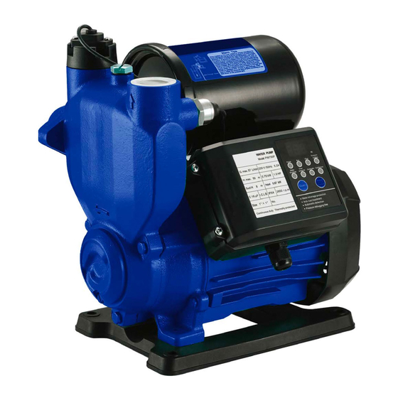
Modell: AP, APS, APS-A, APS-B, APS-C, APS-D
Vor der Inbetriebnahme sicherstellen, dass die Pumpe geerdet ist.
Prüfen, ob der Fehlerstromschutzschalter ordnungsgemäß angebracht ist.
Warnung
Die elektrische Pumpe nicht berühren, während sie in Betrieb ist.
Die elektrische Pumpe nicht ohne Wasser betreiben.
Advertisement
Chapters
Table of Contents

Related Manuals for WITA ADELINO AP


Summary of Contents for WITA ADELINO AP
- Page 1 Installations- und Betriebsanleitung Servicehandbuch Modell: AP, APS, APS-A, APS-B, APS-C, APS-D Vor der Inbetriebnahme sicherstellen, dass die Pumpe geerdet ist. Prüfen, ob der Fehlerstromschutzschalter ordnungsgemäß angebracht ist. Warnung Die elektrische Pumpe nicht berühren, während sie in Betrieb ist. Die elektrische Pumpe nicht ohne Wasser betreiben.
- Page 2 EG-Konformitätserklärung Name des Ausstellers: WITA Sp. z o.o. 86-005 Białe Błota Zielonka, ul. Biznesowa 22 Polen Gegenstand der Erklärung Adelino-Oberflächenpumpe Design: AP..., AP...L, AP...K, AP...A, APS..., APS...-A, APS...-B, APS...-C, APS...-D Wir erklären in alleiniger Verantwortung, dass die oben angegebenen Produkte, auf die sich diese EG-Konformitätserklärung bezieht, den folgenden Normen und Richtlinien entsprechen:...
-
Page 3: Table Of Contents
Inhalt 1. Sicherheitsvorkehrungen • • • • • • • • • • • • • • • • • • • • • • • • • • • • • • • • • • • • • • • • • • • • • • • 2. - Page 4 Vielen Dank, dass Sie sich für unser Produkt entschieden haben. Lesen Sie sich diese Anleitung vor der Installation und Verwendung bitte aufmerksam durch und bewahren Sie sie sorgfältig auf. Bei Installation und Betrieb müssen die örtlichen Bestimmungen eingehalten werden. Unsachgemäße Verwendung kann zu Personenschäden führen. •...
- Page 5 Weist darauf hin, dass Berühren verboten ist, und Nichtbeachtung zum Tod oder zu schweren Verletzungen führt Weist darauf hin, dass die entsprechenden Vorschriften eingehalten werden müssen Weist auf verbotene Handlungen hin, die nicht ausgeführt werden dürfen oder beendet werden müssen Weist auf das Symbol des Schutzleiters zum Schutz vor Stromschlag hin Erklärung Gefahren oder Schäden, die durch eine der nachfolgend aufgeführten Umstände infolge von...
-
Page 6: Sicherheitsvorkehrungen
1. Sicherheitsvorkehrungen 1.1 Die betreffende elektrische Pumpe muss ordnungsgemäß mit einem Der elektrische Anschluss muss Fehlerstromschutzschalter ausgestattet sein und an der Stelle, an der sich das von einem lizenzierten Elektriker in Übereinstimmung mit den Erdungszeichen der elektrischen Pumpe oder des Kabels befindet, eine geltenden örtlichen Vorschriften zuverlässige Erdung aufweisen (der Erdungsleiter muss an die gekennzeichnete und Sicherheitsnormen... -
Page 7: Produktinformationen
1.7 Wenn im Winter Frostschutzmaßnahmen ergriffen werden, darf zum Abdecken der Pumpe oder des Pumpenmotors kein entflammbares Material verwendet werden, da Brandgefahr besteht. Den Motor nicht mit Wärmedämmstoff abdecken, da dieses Material zu einer starken Hitzeentwicklung und dadurch zu einem Brand führen kann. 2. - Page 8 Anschlussplan der Pumpe In den folgenden Abbildungen wird die interne Verkabelung der elektrischen Pumpen dargestellt. Kabeldraht Motor Druckschalter Druckschalter Kondensator gelb-grüner Draht gelb-grüner Draht Kondensator Stecker Stecker Serie APS-A Serie APS-D Druck- Druckschalter Motor schalter Kondensator Thermoschutz Kabeldraht Serie APS-C Verkabelung des Druckschalters bei APS-A und APS-B.
-
Page 9: Technische Daten
3. Technische Daten Die folgende Tabelle enthält die technischen Daten der elektrischen Pumpen der Serien AP, APS, APS-A, APS-B, APS-C, APS-D. Max. Förderhöhenbereich Max. Spannung Strom Leistung Durchfluss Förderhöhe Modell (kW) (m³/h) AP37 0,37 1–27 AP55 0,55 1,5–44 AP75 0,75 2,5–53 AP37L 0,37... -
Page 10: Anwendungsbeispiele
4. Anwendungsbeispiele Anwendungsbereiche der elektrischen Pumpe umfassen die Förderung von Wasser aus Brunnen, Druckbeaufschlagung von Leitungen, landwirtschaftliche Bewässerung, Wasserversorgung von Gewächshäusern, Haushaltswasserversorgung und Tierzucht. In den Abbildungen werden zwei exemplarische Anwendungen dargestellt: Versorgung eines Haushalts mit Leitungswasser und Förderung von Wasser aus einem Brunnen. Lieferung von Leitungswasser durch indirekten Druckaufbau... -
Page 11: Installationsanleitung
5. Installationsanleitung 5.1 Maßnahmen vor der Installation Vor der Installation und Verwendung die elektrische Pumpe vollständig auf Transport- oder Lagerungsschäden überprüfen, z. B. sicherstellen, dass sich Kabel oder abgehende Kabel oder Stecker (falls mitgeliefert) in einwandfreiem Zustand befinden. Wird ein Schaden festgestellt, ist das betreffende Teil von einer Fachkraft auszutauschen oder zu reparieren. - Page 12 2. Vor der Verwendung der Pumpe mit einem Schraubendreher die Lüfterblätter hin- und herbewegen, um zu prüfen, ob sich die elektrische Pumpe reibungslos dreht. 3. Vor der Verwendung der elektrischen Pumpe einen Probelauf von höchstens 10 Sekunden Dauer durchführen, da längeres Trockenlaufen die Gleitringdichtung beschädigen kann.
- Page 13 3. Um die elektrische Pumpe herum einen Entwässerungskanal zur natürlichen Entwässerung anlegen, um Wasseraustritt und -verlust während Verwendung, Reparatur oder Austausch der elektrischen Pumpe zu vermeiden (insbesondere in Keller, Küche oder Treppenhaus). Abwasserrohr anschließen EINGANG AUSGANG 4. Wenn eine elektrische Pumpe mit Drehstrommotor mit einer Überlastschutzvorrichtung ausgestattet werden soll, müssen bei der Auswahl die Strom- oder Leistungsdaten berücksichtigt Warnung...
-
Page 14: Instandhaltung
8. Die Verwendung der Wirbelpumpe nahe dem maximalen Förderhöhenbereich vermeiden, da dies zu Pumpenschäden durch Überlast führen kann. Der Betrieb mit vollständig geöffneter Armatur senkt den Stromverbrauch und spart elektrische Energie. 9. Wenn die Pumpe für warmes oder hartes Wasser oder in älteren Rohren verwendet wird, müssen regelmäßig Verschmutzungen und Rückstände aus dem Rückschlagventil Warnung... - Page 15 6.4 Bei einer Umgebungstemperatur von unter 4 °C muss Wasser, welches sich in der Pumpenkammer angesammelt hat, vollständig abgelassen werden, um frostbedingte Risse im Hinweis Pumpenkörper zu vermeiden. Vor dem erneuten Starten der elektrischen Pumpe sicherstellen, dass sich die Pumpenspindel normal dreht, und dann die Pumpenkammer mit Wasser füllen.
-
Page 16: Problemlösung
7. Problemlösung Vor der Durchführung von Maßnahmen zur Problemlösung sicherstellen, dass die Pumpe ausgeschaltet ist und alle beweglichen Teile stillstehen. Pumpe gegen versehentliches Wiedereinschalten sichern. Störung Ursache Behebung 1. Problem vom Stromversorger beheben lassen oder Spannungsregler hinzufügen; Spannung auf den 0,9- bis 1. - Page 17 Störung Ursache Behebung Den Druckwert des Schalters von Fachpersonal einstellen Elektrische Pumpe Der Druck der Wassereinlauf- und lassen; zunächst den Strom abschalten, die Abdeckung des startet nicht, wenn Wasserauslaufleitung ist höher als der Startdruck Druckschalters abnehmen und mit einem Schraubendreher oder Wasser vorhanden des Druckschalters.
- Page 18 Fehlercodes der elektrischen Pumpen der Serie APS-D Fehleranzeige Fehlerbeschreibung Ursache Behebung 1. Das Rückschlagventil des Fehler des 1. Den Strömungsschalter ausbauen, reinigen und Strömungsschaltesr wird blockiert und kann korrekt wieder einbauen (siehe a unten) Strömungsschalters nicht zurückgestellt werden. 2. Den Strömungsschalter austauschen 2.
-
Page 19: Entsorgungshinweise
8. Entsorgungshinweise Diese Produkt oder Teile davon müssen umweltgerecht entsorgt werden. 1. Die öffentliche oder private Abfallsammlung nutzen. 2. Altbatterien sind gemäß den staatlichen Rücknahmesystemen zu entsorgen. Produkte, die mit dem Symbol der durchgestrichenen Abfalltonne gekennzeichnet sind, müssen getrennt vom Haushaltsabfall entsorgt werden. Wenn ein Produkt mit diesem Symbol das Ende seiner Nutzungsdauer erreicht hat, muss es an einer kommunalen Sammelstelle abgegeben werden. -
Page 20: Anhang
Anhang 9. Anhang Zellenradpumpen AP H (m) AP37K AP55 AP75 AP37 AP37A AP37L Förderstrom (I/min) Förderstrom (m³/h) Selbstansaugende Zellenradpumpen APS H (m) 50 Hz Förderstrom (I/min) Förderstrom (m³/h) H (m) 54 APS55-A APS75-A APS12-A APS25-A APS37-A Förderstrom (I/min) Förderstrom 0.3 0.6 (m³/h) -
Page 21: Aps25-D
Anhang H (m) (I/min) (m³/h) H (m) 48 Förderstrom (I/min) Förderstrom (m³/h) H (m) 60 APS55-D APS75-D APS12-D APS25-D APS37-D Förderstrom (I/min) Förderstrom (m³/h) - Page 23 Installation and operation instructions Service Manual Model: AP, APS, APS-A, APS-B, APS-C, APS-D Make sure the electric pump is grounded before operation Check if leakage protection device is reliably equipped Warning Do not touch the electric pump while it is running Do not run electric pump without water...
- Page 24 EC Declaration of Conformity Name of the issuer: WITA Sp. z o. o. 86-005 Białe Błota Zielonka, ul. Biznesowa 22 Poland Subject of the declaration Adelino Surface Pump Design: AP..., AP...L, AP...K, AP...A, APS..., APS...-A, APS...-B, APS...-C, APS...-D We declare with sole responsibility that the products specified above, to which this EC Declaration of Conformity refers, fulfil the following standards and guidelines:...
- Page 25 Contents 1. Safety Precautions • • • • • • • • • • • • • • • • • • • • • • • • • • • • • • • • • • • • • • • • • • • • • • • • • • • • • • • 2.
- Page 26 Thank you very much for choosing our product. Please read through this instruction manual and keep it properly before installation and use. Installation and operation muss comply with local regulations. Improper use may lead to personal injuries. • Before operation, make sure that the electric pump is grounded reliably and leakage protection device is equipped •...
- Page 27 Indicates that touch is prohibited, which, if ignored, will result in death or serious personal injury Indicates that the relevant rules shall be observed Indicates prohibited actions, which must not be taken or must be stopped Indicates the symbol of ground wire in case of an electric shock Statement: Any hazard or loss caused by any of the following circumstances, where the content hereof is not observed, is not included in the scope of the manufacturer’s quality warranty:...
-
Page 28: Safety Precautions
1. Safety Precautions 1.1 The electric pump involved shall be equipped with a leakage protection Electrical connection shall device properly and reliable grounding shall be provided at the place where be done by a holder of the grounding sign of the electric pump or the cable is located (the grounding an electrician license in accordance with the relevant conductor shall be connected to the marked terminal) and the connected... -
Page 29: Product Information
1.7 When taking anti-freeze measures for the water pump in winter, no flammable material shall be used to cover the pump or its motor for freeze-proofing to avoid any fire accident. Do not cover the motor with any thermal insulation material, because such material can cause 2. - Page 30 2.4 Pump Wiring Diagram The following figures describe the internal wiring details of the electric pumps. APS-A Series APS-D Series APS-C Series APS-A and APS-B Pressure Switch Wiring Diagram Pressure Switch Plug(2-wire) Flow witch lug(3-wire) Pressure Switch...
-
Page 31: Aps25-C
3. Technical Parameter The following table describes the technical data of the electric pumps of AJ, AJS, AJ-A and AJ-C series. Voltage Current Power Max. Flow Max.Head Head Range Model (kW) (m³/h) AP37 0.37 1~27 AP55 0.55 1.5~44 AP75 0.75 2.5~53 AP37L 0.37... -
Page 32: Example Of Applications
4. Example of Applications The electric pumps can be used for lifting water from wells, pipe pressurization, agricultural irrigation, water supply to vegetables greenhouses, supply of domestic water, and breeding industry. Two diagramm examples of pump application iare given: supply of tap water in household and lifting water from well. Indirectly-pressurized supply of tap water lifting water from well... -
Page 33: Installation Instructions
5. Installation Instructions 5.1 Before Installation Prior to installation and use, please fully check whether the electric pump is damaged during transportation or storage, for example, whether any cable or outgoing line or plug (if provided) is in a perfect condition. In case of any damage, please have the replacement or repair carried out by a specialist. - Page 34 2. Before using the pump, please use the screwdriver to toggle the fan blades to check whether the electric pump rotates smoothly. 3. The electric pump shall be conducted test run before use for less than 10s, because long-time dry operation will damage the mechanical seal.
- Page 35 3. Arrange a drainage ditch around the electric pump to form natural drainage and prevent water leakage and loss during the usage, repair, or replacement of the electric pump (especially at a basement, kitchen, or stairway). Connect the sewer 4. To equip a three-phase electric pump with an overload protection device, a suitable overload protection device shall be selected based on its current or power.
- Page 36 8. Avoid using the vortex pump near the maximum head range which can damage the electric pump due to overload. The full-open use of the faucet consumes little power and saves the electric energy. 9. When the pump is used for pumping hot or hard water, or it is used in aged pipelines, you need to regularly clean the stains and impurities on the check valve and filter screen to avoid the failure of the flow switch.
- Page 37 6.4 When the ambient temperature is lower than 4°C, please completely drain the water accumulated in the pump chamber to avoid frost-cracking the pump body. Before starting the Notice electric pump again, inspect whether the pump spindle can rotate normally and then fill the pump chamber with water. 6.5 If the electric pump will not be used for a long time, please disassemble the piping, drain the water accumulated in the pump, clean the main parts and components, carry out rust-...
-
Page 38: Troubleshooting
7. Troubleshooting Before performing any troubleshooting, make sure the pump has been turned off and all moving components have stopped rotating. Make sure that the pump cannot be turned on accidentally. Fault Cause Remedy 1. Ask the electric power company to solve or add the voltage; regulator and adjust the voltage to 0.9–1.1 times of the rated value 1. - Page 39 Fault Cause Remedy Ask the profession personnel to properly adjust the switch The electric pump The pressure of the water inlet and outlet pipeline pressure value, first cut off the power, remove the pressure switch does not start when is higher than the starting pressure of the cover and use the screwdriver or wrench to slowly turn it in the “+“...
- Page 40 Fault codes of APS-D series electric pumps Fault Fault description Cause Remedy display 1. The check valve of flow switch is stuck 1. Remove the flow switch for cleaning and install it by something and cannot reset back correctly (see below a) Failure of flow switch 2.
-
Page 41: Recycling Information
8. Recyling Information This product or parts of it must be disposed of in an environmentally sound way. 1. Use the public or private waste collection service. 2. Dispose of the waste battery through the national collective schemes. The crossed-out wheelie bin symbol on a product means that it must be disposed of separately from household waste. -
Page 42: Aps55-C
Appendix 9. Appendix AP Peripheral Pumps H(m) AP37K AP55 AP75 AP37 AP37A AP37L Q(L/min) Q(m³/h) APS Self-Priming Peripheral Pumps H(m) 50Hz Q(L/min) Q(m³/h) H(m) 54 APS55-A APS75-A APS12-A APS25-A APS37-A 60 Q(L/min) 0.3 0.6 3.6 Q(m³/h) - Page 43 Appendix H(m) H(m) 48 60 Q(L/min) Q(m³/h) H(m) 60 APS55-D APS75-D APS12-D APS25-D APS37-D 60 Q(L/min) 3.6 Q(m³/h)
- Page 45 Instrukcja montażu i obsługi Instrukcja obsługi Model: AP, APS, APS-A, APS-B, APS-C, APS-D Przed rozpoczęciem eksploatacji upewnić się, czy pompa elektryczna jest uziemiona Sprawdzić, czy zabezpieczenie upływowe zostało należycie zamontowane Ostrzeżenie Nie dotykać pompy elektrycznej w trakcie pracy Nie uruchamiać pompy elektrycznej bez wody...
- Page 46 Deklaracja zgodności CE Dystrybutor: WITA Sp. z o.o. 86-005 Białe Błota Zielonka, ul. Biznesowa 22 Polska Przedmiot deklaracji: Pompa powierzchniowa Adelino Model: AP..., AP...L, AP...K, AP...A, APS..., APS...-A, APS...-B, APS...-C, APS...-D Z pełną odpowiedzialnością oświadczamy, że podane wyżej produkty, których dotyczy niniejsza Deklaracja Zgodności CE, spełniają...
- Page 47 Spis treści 1. Środki bezpieczeństwa • • • • • • • • • • • • • • • • • • • • • • • • • • • • • • • • • • • • • • • • • • • • • • • 2.
- Page 48 Dziękujemy za wybranie naszego produktu. Prosimy o przeczytanie niniejszej instrukcji i zachowanie jej na czas montażu i użytkowania. Montaż i obsługa muszą być przeprowadzone zgodne z niniejszą instrukcją oraz lokalnymi przepisami. Niewłaściwe użytkowanie może doprowadzić do obrażeń ciała. • Przed rozpoczęciem eksploatacji należy upewnić się, czy pompa elektryczna jest prawidłowo uziemiona i czy zamontowano zabezpieczenie upływowe •...
- Page 49 Symbol ten oznacza, że obowiązuje zakaz dotykania, a jego złamanie prowadzi do śmierci lub poważnych uszkodzeń ciała. Symbol ten oznacza, że należy przestrzegać oznaczonych nim zasad. Symbol ten oznacza czynności zabronione, których nie wolno podejmować i które należy powstrzymywać. Symbol ten oznacza przewód uziemiający – na wypadek porażenia prądem elektrycznym.
- Page 50 1. Środki bezpieczeństwa 1.1 Pompa elektryczna powinna mieć właściwie zamontowane zabezpieczenie Podłączenie do instalacji upływowe, a w miejscu, w którym znajduje się znak uziemienia pompy elektrycznej powinien wykonać elektryk z uprawnieniami elektrycznej lub przewodu, należy zapewnić prawidłowe uziemienie (przewód zgodnymi z odpowiednimi uziemiający należy podłączyć...
- Page 51 1.7 W przypadku stosowania środków zapobiegających zamarzaniu pompy wodnej w zimie, nie należy używać materiałów łatwopalnych do pokrycia pompy lub jej silnika w celu zabezpieczenia przed zamarzaniem, aby nie doszło do pożaru. Nie należy przykrywać silnika materiałami termoizolacyjnymi, ponieważ mogą one doprowadzić...
- Page 52 2.4 Schemat instalacji elektrycznej pompy Następujące rysunki przedstawiają szczegóły wewnętrznej instalacji elektrycznej pomp elektrycznych. Przewód zasilający Kabeldraht Silnik Przełącznik Druckschalter ciśnieniowy Silnik Kondensator Przewód żółto- zielony gelb-grüner Draht Kondensator Wtyk Stecker Seria APS-A Seria APS-D Przełącznik Druckschalter ciśnieniowy Silnik Kondensator Zabezpieczenie Thermoschutz termiczne...
- Page 53 3. Parametry techniczne Następująca tabela przedstawia dane techniczne dotyczące pomp elektrycznych z serii AJ, AJS, AJ-A, AJ-C i APS-D. Zakres Maks. Maks. Natężenie podnoszenia podnoszenie Moc (kW) przepływ Model Napięcie (V) (m³/h) AP37 0,37 1–27 AP55 0,55 1,5–44 AP75 0,75 2,5–53 AP37L 0,37...
- Page 54 4. Przykład zastosowań Pompy elektryczne mogą być stosowane do tłoczenia wody ze studni, utrzymywania ciśnienia w rurociągach, nawadniania pól uprawnych, doprowadzania wody do szklarni warzywnych, doprowadzania wody w gospodarstwie domowym oraz w branży hodowlanej. Na poniższych schematach przedstawiono dwa przykłady zastosowań pomp: doprowadzanie wody bieżącej w gospodarstwie domowym oraz tłoczenie wody ze studni.
- Page 55 5. Instrukcje montażu 5.1 Przystąpienie do montażu 6. Przed montażem i obsługą należy dokładnie sprawdzić, czy pompa elektryczna nie została uszkodzona podczas transportu lub przechowywania, np. czy wychodzący przewód lub wtyk (jeśli są w zestawie) są w idealnym stanie. W przypadku jakichkolwiek uszkodzeń...
- Page 56 2. Przed użyciem pompy należy użyć śrubokrętu w celu obrócenia łopatek wentylatora, aby sprawdzić, czy pompa elektryczna pracuje płynnie. 3. Przed użyciem pompy elektrycznej należy wykonać rozruch próbny, którego czas trwania nie powinien przekraczać 10s, ponieważ długotrwały rozruch na sucho spowoduje uszkodzenie uszczelnienia mechanicznego.
- Page 57 3. Wokół pompy elektrycznej należy zapewnić kanał odpływowy, aby utworzyć naturalny drenaż i zapobiec wyciekom i stratom wody podczas użytkowania, naprawie lub wymianie pompy elektrycznej (zwłaszcza w piwnicy, kuchni lub na klatce schodowej). Podłączyć do sieci kanalizacyjnej Abwasserrohr anschließen MOC WEJŚCIOWA MOC WYJŚCIOWA EINGANG AUSGANG...
- Page 58 8. Należy unikać używania pompy wirowej w oklicach maksymalnej wysokości podnoszenia, gdyż może to spowodować uszkodzenie pompy na skutek przeciążenia. Używanie kranu przy pełnym otwarciu powoduje niskie zużycie mocy i energii elektrycznej. 9. Gdy pompa jest używana do pompowania gorącej lub twardej wody, lub gdy jest używana w starych rurociągach, należy regularnie czyścić...
- Page 59 6.4 Gdy temperatura otoczenia wynosi mniej niż 4°C, należy całkowicie spuścić wodę nagromadzoną w komorze pompy, w celu uniknięcia pęknięcia korpusu pompy na skutek mrozu. Uwaga Przed ponownym uruchomieniem pompy należy sprawdzić, czy wrzeciono pompy może normalnie się obracać i następnie napełnić...
- Page 60 7. Rozwiązywanie problemów Przed przystąpieniem do rozwiązywania jakichkolwiek problemów należy upewnić się, że pompa została wyłączona, a wszystkie ruchome elementy przestały się poruszać. Należy upewnić się, że pompa nie może zostać przypadkowo włączona. Awaria Przyczyna Rozwiązanie 1. Zlecić rozwiązanie problemu lub zamontowanie regulatora napięcia zakładowi energetycznemu i dostosować...
- Page 61 Awaria Przyczyna Rozwiązanie Pompa elektryczna Zlecić specjalistycznemu personelowi prawidłowe wyregulowanie nie uruchamia się, Ciśnienie w rurze wlotowej i wylotowej jest wyższe wartości ciśnienia przełącznika; najpierw należy odciąć zasilanie, gdy używana jest niż ciśnienie początkowe przełącznika ciśnienia zdjąć pokrywę przełącznika ciśnienia i użyć śrubokrętu lub klucza, woda aby wolno przekręcić...
- Page 62 Kody błędów pomp elektrycznych z serii APS-D Sygnalizacja Awaria Przyczyna Rozwiązanie usterki 1. Zawór zwrotny przełącznika przepływu 1. Zdemontować przełącznik przepływu, aby go jest zablokowany i nie może zostać oczyścić i ponownie go zamontować w prawidłowy Usterka przełącznika odblokowany sposób (patrz niżej – punkt a) przepływu 2.
- Page 63 8. Informacje o recyklingu Niniejszy produkt lub jego części należy utylizować w sposób przyjazny dla środowiska. 1. Korzystać z publicznych lub prywatnych punktów przyjmowania odpadów. 2. Zużyte baterie wyrzucać zgodnie z krajowymi programami dot. zbiórki odpadów Przekreślony symbol pojemnika na śmieci oznacza, że odpady należy usuwać oddzielnie od odpadów bytowych. Z chwilą...
- Page 64 Załącznik 9. Załącznik Pompy odśrodkowe AP H (m) AP37K AP55 AP75 AP37 AP37A AP37L Förderstrom Q (l/min) (I/min) Förderstrom Q (m3/h) (m³/h) Samozasyjające pompy odśrodkowe APS H (m) 50 Hz Förderstrom Q (l/min) (I/min) Förderstrom Q (m3/h) (m³/h) H (m) 54 APS55-A APS75-A APS12-A...
- Page 65 Załącznik H (m) Q (l/min) (I/min) (m³/h) Q (m3/h) H (m) 48 Förderstrom Q (l/min) (I/min) Förderstrom Q (m3/h) (m³/h) H (m) 60 APS55-D APS75-D APS12-D APS25-D APS37-D Q (l/min) Förderstrom (I/min) Förderstrom Q (m3/h) (m³/h)
Need help?
Do you have a question about the ADELINO AP and is the answer not in the manual?
Questions and answers