Table of Contents
Advertisement
Quick Links
OPERATOR'S MANUAL
INCLUDING: OPERATION, INSTALLATION AND MAINTENANCE
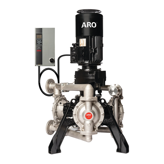
2" EVO SERIES ELECTRIC DIAPHRAGM PUMP
INGERSOLL RAND COMPANY INC
209 NORTH MAIN STREET – BRYAN, OHIO 43506
(800) 495-0276
FAX (800) 892-6276
arozone.com
(METALLIC FLUID SECTIONS)
© 2022
EP20-XXXXX-XXX-XXX
RELEASED:
1-28-22
(REV: A)
Advertisement
Table of Contents

Related Manuals for Ingersoll-Rand ARO EVO EP20 Series


Summary of Contents for Ingersoll-Rand ARO EVO EP20 Series
- Page 1 OPERATOR’S MANUAL EP20-XXXXX-XXX-XXX INCLUDING: OPERATION, INSTALLATION AND MAINTENANCE RELEASED: 1-28-22 (REV: A) 2” EVO SERIES ELECTRIC DIAPHRAGM PUMP (METALLIC FLUID SECTIONS) INGERSOLL RAND COMPANY INC 209 NORTH MAIN STREET – BRYAN, OHIO 43506 (800) 495-0276 FAX (800) 892-6276 ©...
-
Page 2: Table Of Contents
TABLE OF CONTENTS 1. TECHNICAL SPECIFICATIONS ....3 8. GROUNDING ........23 1.1. -
Page 3: Technical Specifications
1. TECHNICAL SPECIFICATIONS 1.1. Pump Data Models ..See Model Description Chart for “-XXXXX”. Maximum Temperature Limits Pump Type . . Electric Diaphragm Pump Material ..See Model Description Chart ... -
Page 4: Electric Motor Data
1.3. Electric Motor Data ORDINARY MOTOR HAZARDOUS MOTOR (Black) (Red) Figure 1 ORDINARY HAZARDOUS Part Number 67559 67560-1 Rated Power 5.5 kw 5.5 w Rated Torque 36 Nm 36 Nm Efficiency Number Of Phases Polarity Voltage 400V 400V Frequency 50 Hz 50 Hz Index Of Protection IP66... -
Page 5: Nameplate Details
Viton® is a registered trademarks of the Chemours Company Hytrel® is a registered trademark of the DuPont Company Loctite® is a registered trademark of Henkel Corporation Santoprene® is a registered trademark of Celanese ARO® is a registered trademark of Ingersoll-Rand Company ... -
Page 6: Model Description Chart
2. MODEL DESCRIPTION CHART 2.1. Model Code Explanation Wetted Parts Aluminum C - Cast Iron S - Stainless Steel Port F - ANSI / DIN Hybrid Flange Seat A - Santoprene® F - Aluminum H - 440 SST S - 316 SST Ball A - Santoprene®... -
Page 7: Operating And Safety Precautions
3. OPERATING AND SAFETY PRECAUTIONS READ, UNDERSTAND, AND FOLLOW THIS INFORMATION TO AVOID INJURY AND PROPERTY DAMAGE. All electrical wiring must be done by a qualified elec- EXCESSIVE FLUID PRESSURE HAZARDOUS MATERIALS trician and comply with all local codes and regula- STATIC SPARK HAZARDOUS PRESSURE tions. -
Page 8: General Description
Do not use the pump for the structural TORQUE ALL FASTENERS BEFORE OPER- CAUTION NOTICE support of the piping system. Be certain the system ATION. Creep of housing and gasket materials may components are properly supported to prevent stress cause fasteners to loosen. Torque all fasteners to en- on the pump parts. -
Page 9: Mechanical Installation
5. MECHANICAL INSTALLATION 5.1. Pump and Motor Installation WARNING Pump and motors are industrial products. They must therefore be installed by qualified, experienced and autho- rized personnel. The safety of people, animals and property must be ensured when fitting the motors into pump. CAUTION Prior to commissioning for all motors, rotate the motor at no load (no mechanical load) for 2 to 5 minutes, checking that there is no abnormal noise. -
Page 10: Vfd Mechanical Installation
5.3. VFD Mechanical installation The ordinary motor gearbox will also need to have a breather installed after installation to the pump. Refer to section 3 of VFD manual for detailed mechanical Remove the temporary metallic plug from breather port. installation. -
Page 11: Electrical Installation For Ordinary Locations
6. ELECTRICAL INSTALLATION FOR ORDINARY LOCATIONS 6.1. VFD-Wiring Diagram 3-phase 91 (L1) (U) 96 power 92 (L2) (V) 97 input 93 (L3) (W) 98 (PE) 99 Motor Switch mode 88 (-) power supply DC bus 89 (+) 10 V DC 24 V DC Brake (R+) 82... -
Page 12: Vfd Ac Mains - Input Power Requirements
6.3. VFD AC Mains – Input Power Requirements: Supply terminals (6-pulse) L1, L2, L3 (1)(2) Supply voltage 380 – 500 V +/- 10% Supply frequency 47.5 – 63 Hz Maximum imbalance temporary between mains phases 3.0% of rated supply voltage True power factor (λ) ≥... -
Page 13: Motor - Input Power Wiring
6.4.3. Motor - Input Power Wiring The cables must be fitted with connectors suitable for the cable cross-section and the terminal diameter. They must be crimped in accordance with the connector supplier’s instructions. If using cables without connectors, attach some calipers. ... - Page 14 Leak Detect Diaphragm 1 White Pin 18 on VFD (Digital input) Black Pin 19 on VFD (Digital input) Leak Detect Diaphragm 2 White Pin 13 on VFD (24V DC) Black Pin 20 on VFD (Common) Leak Detect Diaphragm 3 White Pin 32 on VFD (Digital input) Black...
-
Page 15: Thermal Protection - Ordinary Motor
6.5.2. Thermal protection – Ordinary motor Motor is installed with 2 normally closed contact sensors (PTO) in series for ordinary motors and will need to be wired from the motor terminal box to the VFD as per below wiring diagram. Cable extension and cable glands are not provided. It is recommended to use the M16 cable gland on the motor terminal box for the PTO control cable. -
Page 16: Control Wiring (Recommended)
6.6. Control Wiring (Recommended) 6.6.1. Safe Stop wiring diagram It is recommended to install an external Emergency Stop (Safe Stop). Referred to in VFD manual as Safe Torque Off (STO). The VFD will come with pin 37 (E-stop digital input) wired to 24V (pin 12 or 13). This jumper will need to be removed when ... -
Page 17: Analog Input - Speed Control
6.7.2. Analog Input – Speed control A 0 - 10 V or 4 - 20 mA signal can be used to control VFD speed from 0 - 100% using analog input 53. The VFD is set to receive a 0-10 V input signal as configured from the factory. To change to 4-20 mA input signal, toggle the ... -
Page 18: Additional Available Input/Output (Optional)
6.7.4. Additional available Input/output (Optional) 1. T27 and T29 are configurable for digital input or output. Digital output can be either digital or pulse output. The options for parameters 530 and 531 are all digital, however, to enable pulse output the parameters in the table below should be set as shown. The pulse output variable can then be selected using parameters 560 and 563. -
Page 19: User Defined Readout
Fieldbus Communication Option A Cards: These are available for aftermarket installation only and should be installed in the VFD option A slot. Please note this is only available for ordinary applications. Part Number Description 130B1200 Profibus DP VI MCA 101, coated 130B1202 DeviceNet MCA 104, coated 130B1205... -
Page 20: Electrical Installation For Hazardous Locations
7. ELECTRICAL INSTALLATION FOR HAZARDOUS LOCATIONS 7.1. General Wiring Cable glands and plugs shall be selected in accordance with IEC 60079-0 and EPL Gb/Db at the minimum. They must be Before commissioning verify that the information shown on correctly sized, tightened, and gripped and account for any the nameplate is compatible with explosive atmosphere that coldflow characteristics of the cables. -
Page 21: Thermal Protection - Hazardous
Leak Detector Safe Loop Calculations Leak Detector Cable Zener Barrier IR Part Number 96270-2 Alpha Wire 1173C IR Part Number 97414 Ui = 32 VDC Uo = 25.2 VDC Ii = 87 mA Io = 74 mA Pi = 0.616 W Po = 0.464 W Ci = 0.052 uF Cc 0.055uF... -
Page 22: Encoder Wiring - Hazardous Motor
7.3.3 Encoder Wiring - Hazardous Motor The hazardous duty motor will come with a 1024pt TTL encoder with 10 meters of cable lengths and flying lead connec- tions. The motor will ship without the encoder installed to minimize the chance of damage during shipping and installa- tion since the encoder is installed on top of the rain canopy. -
Page 23: Grounding
8. GROUNDING 8.2. VFD Grounding Before operating the pump, ground the system as explained below. LEAKAGE CURRENT HAZARD WARNING Leakage currents exceed 3.5 mA. Failure to ground the drive 8.1. Pump Grounding properly can result in death or serious injury. All pumps have a ground screw installed in Crankcase ... -
Page 24: Operation
9. OPERATION 9.1. Pre Operation Checklist VFD is configured according to the motor requirement. The outlet material volume is governed not only by the Close the safety cover properly and check that all cable Fluid pressure but also by the material supply available ... -
Page 25: Vfd Smart Setup
Parame- Description Function Set the maximum frequency for terminal 29, corresponding to the output variable selected in pa- Pulse Output Max Freq #29 rameter 563. Function Relay Define relay functions using 540.0 and 540.1 (2 relays available). Enter the low voltage value (Default 0.07V). This corresponds to the minimum reference value of 0 Terminal 53 Low Voltage Enter the high voltage value (Default 10V). -
Page 26: Maintenance
10. MAINTENANCE Refer to the part views and descriptions as provided on page 27 through 36 for parts identification and Service Kit information. Service kits are divided to service four separate section: 1. Before disassembling CRANKCASE SECTION, 2. FLUID SECTION, 3. PRV SECTION, Empty oil from Crankcase housing through drain port. -
Page 27: Subsystem Overview
11. SUBSYSTEM OVERVIEW PARTS LIST / FLUID SECTION EP20-XXXXX-XXX-XXXX Fluid Section Service Kits: 637555-XX Fluid Section Service Kits include: Balls (see BALL Option, refer to -XX in chart below), Diaphragms (see DIAPHRAGM Op- tion, refer to -XX in chart below), and items 3, 4, 12 and 13 (listed below). EXTERNAL HARDWARE OPTIONS EP20-XXXXX-XXX-XXX COMMON PARTS Aluminum /... - Page 28 PARTS LIST / FLUID SECTION EP20-XXXXXX-XXX-XXX COLOR CODE Material Diaphragm Ball )ASSEMBLY TORQUE REQUIREMENTS( Color Color NOTE: DO NOT OVERTIGHTEN FASTENERS. Santoprene Santoprene Green (14) Screw, tighten to 55 - 60 ft lbs (75 - 81 Nm). (Backup) (26, 68) Screws, 20 - 25 ft lbs (27 - 34 Nm). PTFE White White...
- Page 29 FLUID SECTION DISASSEMBLY FLUID SECTION REASSEMBLY Remove inlet Manifolds (60, 64, 65) and outlet Manifolds Reassemble parts in reverse order from the sequence in (61, 62, 63) together. which they were removed. Refer to the torque require- Separate inlet wye Manifold (60), Inlet PRV Manifold (65) ments on page 28.
-
Page 30: Prv Section
PARTS LIST / PRV EP20-XXXXX-XXX-XXX MANIFOLD / HOUSING MATERIAL OPTIONS EP20-XXXXX-XXX-XXX Aluminum Cast Iron Stainless Steel Item Description Part No. [Mtl] Part No. [Mtl] Part No. [Mtl] (size) PRV ASSY 67557-1 67557-2 67557-3 44 Housing, PRV 97971 98073 [CI] 98087 [SS] Manifold, PRV Return... - Page 31 PARTS LIST / PRV EP20-XXXXX-XXX-XXX See Detail A )ASSEMBLY TORQUE REQUIREMENTS( NOTE: DO NOT OVERTIGHTEN FASTENERS. (53) Nut, tighten to 7 - 10 ft lbs (10 - 14 Nm). (55) Bolt, tighten to 20 - 25 ft lbs (27 - 34 Nm). DETAIL A Figure 13 EP20-XXXXX-XXX-XXX (en)
-
Page 32: Crankcase Section
PARTS LIST / CRANKCASE EP20-XXXXX-XXX-XXX Pump Crankcase Replacement Assembly EP20-CSVX-00-A : Includes all Items shown in the Crankcase parts list (below) except for item 283. Includes all items shown in the oil pump parts list (page 35). Includes items 13, 16 and 17 shown on page 27. Note: Crankcase components are designed for the intended life of the pump. - Page 33 PARTS LIST / CRANKCASE EP20-XXXXX-XXX-XXX Grease inner diameter of seal only )ASSEMBLY TORQUE REQUIREMENTS( NOTE: DO NOT OVERTIGHTEN FASTENERS. (104) Screw, tighten to 20 - 23 ft lbs (27 - 31 Nm). (106) Screw, tighten to 30 - 35 ft lbs (40 - 47 Nm). (115) Screws, 8 - 12 ft lbs (11 - 16 Nm).
- Page 34 Remove internal snap ring (136) and the wrist pin (135). Lower Crankshaft assembly vertically inside Crankcase Remove the piston rod (134) and rider band (133). housing (101) and allow inner race of lower bearing to Journal Bearing (139) is press fitted in to the connecting ...
-
Page 35: Oil Piston Pump Section
PARTS LIST / OIL PISTON PUMP ASSEMBLY SECTION EP20-XXXXX-XXX-XXX Item Description (size) Qty Part No. [Mtl] Item Description (size) Qty Part No. [Mtl] 128 Plug Y17-52-S [SS] (3/8” - 18 NPT) 164 Plug Y17-50-S [SS] (1/8” -18 NPT ) (not shown) 129 Fitting 98059 (9/16”-18 STOR x 3/8”, 90°) - Page 36 PARTS LIST / OIL FILTER EP20-XXXXX-XXX-XXX )ASSEMBLY TORQUE REQUIREMENTS( NOTE: DO NOT OVERTIGHTEN FASTENERS. (129, 176) Straight Thread O-Ring, tighten to 20-25 ft lbs (27-34 Nm) (150) Screws, tighten to 8-12 ft lbs (11-16 Nm) (174, 175) Screws, tighten to 20-30 in lbs (2.2-3.4 Nm) )129 (158) Plug, tighten to 45-50 ft lbs (61-68 Nm) (179) Fitting Body, tighten to 45-50 ft lbs (61-68 Nm)
-
Page 37: Troubleshooting
12. TROUBLESHOOTING Issue Possible Cause Action See manual section 6 and 7 for proper wiring instruc- Improper power wiring: Mains to VFD, VFD to Motor. tions. Improper sensor wiring: Leak detects, e-stop, motor ther- See manual section 6 and 7 for proper wiring instruc- mal sensor, motor encoder. -
Page 38: Dimensional Data
13. DIMENSIONAL DATA 13.1 Pump With Motor (Dimensions shown are for reference only, they are displayed in inches and millimeters (mm)). 51.79” (1315.4 mm) Ordinary pump height 3.31” 1.81” Outlet (84 mm) (46 mm) 2" ANSI / DIN Flange 39.27” (997.6 mm) 1/8”... -
Page 39: Variable Frequency Drive (Vfd)
13.2. Variable Frequency Drive (VFD) VARIABLE FREQUENCY DRIVE (VFD) SEE DETAIL 9.53” 0.25” (242 mm) (6.42 mm) 16.54” (420.2 mm) 15.81” (401.7 mm) 0.39” 8.46” (10 mm) 0.53” DRIVE DISCONNECT (215 mm) (13.5 mm) SEE DETAIL 5.40” 2.82” (137.3 mm) (71.7 mm) 4.05”... -
Page 40: Performance Curve
14. PERFORMANCE CURVE EP20-XXXXX-XXX-XXA 2" EVO ELECTRIC DIAPHRAGM PUMP (METALLIC FLUID SECTION) Performance based on water at ambient temperature. CAPACITY IN U.S. GALLONS PER MINUTE Performance based on water at ambient temperature. FLOW RATE (LITERS / MIN.) Drive Controls: Motor Frequency ≈ Flow Torque limit ≈... -
Page 41: Certification
15. CERTIFICATION See PN 97999-1972 (S-1639, Declaration of Conformity) for details. EP20-XXXXX-XXX-XXX (en) Page 41 of 44... -
Page 42: Warranty Declaration
Internet sites and unauthorized storefronts on online marketplaces. Ingersoll-Rand / ARO will provide a new part or repaired part, at its election, in place of any part which is found upon its inspec- tion to be defective in material and workmanship during the period described above. Such part will be repaired or replaced without charge to the initial end customer during normal working hours at the place of business of a Reseller authorized to sell the type of Product involved or other establishment authorized by Company. - Page 43 EP20-XXXXX-XXX-XXX (en) Page 43 of 44...
- Page 44 About Ingersoll Rand Ingersoll Rand Inc. (NYSE:IR), driven by an entrepreneurial spirit and ownership mindset, is dedicated to helping make life better for our employees, customers and communities. Customers lean on us for our technology-driven excellence in mission-critical flow creation and industrial solutions across 40+ respected brands where our products and services excel in the most complex and harsh conditions. Our employees develop customers for life through their daily commitment to expertise, productivity and efficiency.
Need help?
Do you have a question about the ARO EVO EP20 Series and is the answer not in the manual?
Questions and answers