Table of Contents
Advertisement
Quick Links
OPERATOR'S MANUAL
INCLUDING: OPERATION, INSTALLATION AND MAINTENANCE
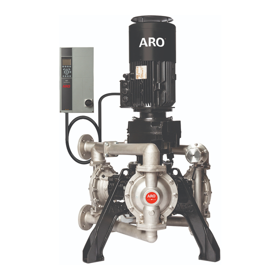
2" ELECTRIC OPERATED POSITIVE DISPLACEMENT PUMP
INGERSOLL RAND COMPANY INC
209 NORTH MAIN STREET – BRYAN, OHIO 43506
(800) 495-0276
FAX (800) 892-6276
arozone.com
1:1 RATIO (METALLIC)
© 2021
EP20-XXXXX-XXX-XXX
RELEASED:
XX-XX-21
(REV: A)
Advertisement
Table of Contents

Related Manuals for Ingersoll-Rand ARO EP20 Series


Summary of Contents for Ingersoll-Rand ARO EP20 Series
- Page 1 OPERATOR’S MANUAL EP20-XXXXX-XXX-XXX INCLUDING: OPERATION, INSTALLATION AND MAINTENANCE RELEASED: XX-XX-21 (REV: A) 2” ELECTRIC OPERATED POSITIVE DISPLACEMENT PUMP 1:1 RATIO (METALLIC) INGERSOLL RAND COMPANY INC 209 NORTH MAIN STREET – BRYAN, OHIO 43506 (800) 495-0276 FAX (800) 892-6276 ©...
-
Page 2: Table Of Contents
TABLE OF CONTENTS 1. TECHNICAL SPECIFICATIONS ................3 1.1. -
Page 3: Technical Specifications
1. TECHNICAL SPECIFICATIONS 1.1. Pump Data Models ..See Model Description Chart for “-XXXXX”. Maximum Temperature Limits Pump Type . . Electric Operated Positive (Diaphragm / Ball / Seat material) Displacement Pump (EOPD) E.P.R. -
Page 4: Electric Motor Data
1.3. Electric Motor Data ORDINARY MOTOR HAZARDOUS MOTOR Figure 1 ORDINARY Hazardous Part Number 67559 67560-1 67560-2 Rated Power 5.5 kw 5.5 w 5.5 kw Rated Torque 36 Nm 36 Nm 36 Nm Efficiency Number Of Phases Polarity Voltage 400V 400V 400V Frequency... -
Page 5: Nameplate Details
1.4. Nameplate Details Items supplied vary according to product configuration. Make sure that the items supplied and the information on the nameplate correspond to the order confirmation. ARO ___ SERIES PUMPS EP20-AFAAA-CSV-ABA PUMP MODEL PUMP MODEL SPG2231001 SERIAL NO ASSEMBLED IN 12.4 AVG W.P. -
Page 6: Model Description Chart
2. MODEL DESCRIPTION CHART Model Code Explanation Wetted Parts Aluminum C - Cast Iron S - Stainless Steel Port F - ANSI/DIN Hybrid Flange Seat A - Santoprene C - Hytrel F - Aluminum H - 440 SST S - 316 SST Ball A - Santoprene C - Hytrel... -
Page 7: Operating And Safety Precautions
3. OPERATING AND SAFETY PRECAUTIONS READ, UNDERSTAND, AND FOLLOW THIS INFORMATION TO AVOID INJURY AND PROPERTY DAMAGE. All electrical wiring must be done by a qualified elec- EXCESSIVE FLUID PRESSURE HAZARDOUS MATERIALS trician and comply with all local codes and regula- STATIC SPARK HAZARDOUS PRESSURE tions. -
Page 8: General Description
Prevent unnecessary damage to the TORQUE ALL FASTENERS BEFORE OPER- CAUTION NOTICE pump. Do not allow pump to operate when out of ma- ATION. Creep of housing and gasket materials may terial for long periods of time. cause fasteners to loosen. Torque all fasteners to en- Disconnect power supply from motor when system sure against fluid or air leakage. -
Page 9: Mechanical Installation
5. MECHANICAL INSTALLATION 5.1. Pump & Motor Installation 5.2. VFD Mechanical installation Refer to section 3 of VFD manual for detailed mechanical WARNING Pump and motors are industrial products. They must therefore be installed by qualified, experienced and autho- installation. rized personnel. -
Page 10: Electrical Installation
6. ELECTRICAL INSTALLATION 6.1. VFD-Wiring Diagram 3-phase 91 (L1) (U) 96 power (V) 97 92 (L2) input 93 (L3) (W) 98 (PE) 99 Motor Switch mode 88 (-) power supply DC bus 89 (+) 10 V DC 24 V DC Brake (R+) 82 15 mA 130/200 mA... -
Page 11: Vfd Ac Mains - Input Power Requirements
6.3. VFD AC Mains – Input Power Requirements: WARNING To ensure the power line, the drive and motor rated for the same voltage Supply terminals (6-pulse) L1, L2, L3 (1)(2) Supply voltage 380 – 500 V +/- 10% Supply frequency 47.5 –... -
Page 12: Control Wiring (Required)
Mains input, motor, and grounding for basic drives. Actual con gurations vary with unit types and optional equipment Figure 5 NOTE: Motor should be wired for wye or star configuration with V and W leads switched as shown in wiring diagram to get the desired direction of rotation. -
Page 13: Leak Detector Safe Loop Calculations
ZENER Barrier, Leak Detection Sensor PN Voltage Device Rating (mA) Temperature Rating 97414 (ATEX / IECEx / NEC / CEC) 24 VDC -4 ° F - 140 ° F (-20 ° C - 60 ° C) Leak Detection Sensor PN Voltage Device Rating (mA) Temperature Rating... -
Page 14: Thermal Protection - Ordinary Motor
6.5.3. Thermal protection – Ordinary motor Motor is installed with 2 normally closed contact sensors (PTO) in series for ordinary motors and will need to be wired from the motor terminal box to the VFD as per below wiring diagram. PTO Thremal switches (Installed on motor) Pin 20 on VFD... -
Page 15: Encoder Wiring - Ordinary Motor
6.5.5. Encoder Wiring – Ordinary Motor Motor is installed with a 1024 pts TTL encoder with a 12-pin connector on the outside of the motor terminal box. Extension cable is available for different length and need to order according to requirement. flying leads need to be wired to the MCB102 encoder card installed in the option B slot of the VFD as per encoder card wir- ing. -
Page 16: Digital Start/ Stop Control
6.6.2. Digital start/ stop control 1. Digital input 27 will be used in place of 18 shown in the VFD manual. The VFD will come with pin 37 wired to 24VDC. This will need to be removed when e-stop is installed. 2. -
Page 17: Analog Inputs - Torque (Pressure) Control
6.7.2. Analog Inputs – Torque (Pressure) Control To active torque control, VFD parameter 420 needs to be changed from “[0] No Function” to “[6] Analog in 54”. Torque and speed control when put together in the system, torque control will override speed control and maintain load on the motor. -
Page 18: Configured I/O's (Summary)
6.8. Configured I/O’s (summary) Intended function Warning text Digital I/O Terminal Ground Terminal 24VDC Terminal Diaphragm 1 Leak Detect Diaphragm 1 Leak Diaphragm 2 Leak Detect Diaphragm 2 Leak Diaphragm 3 Leak Detect Diaphragm 3 Leak PTO (normally closed) - Alarm 11 N / A Ordinary pump only... -
Page 19: User Defined Readout
6.10. User defined readout Parameters 030, 031, & 032 are available to modify the “User Defined Readout” that will display in the top left corner of the main menu screen. By default, these values are set to scale motor frequency to actual pump rpm. To update the “User De- fined Readout”, refer to the following parameter descriptions. -
Page 20: Lubrication Requirement
8. LUBRICATION REQUIREMENT 8.1. Oil Filling instruction WARNING You must use lubricating oil of the recommended type. Pump is shipped with 2.5 gallon Oil container. Crankcase Pump is lubricated at the factory. Pump is shipped with syn- unit will hold approx. 1.7 gallons (6.4 L). Store leftover oil thetic oil PAO ISO VG 460. -
Page 21: Operation
9. OPERATION 9.1. Pre Operation Checklist VFD is configured according to the motor requirement. The outlet material volume is governed not only by the Close the safety cover properly and check that all cable Fluid pressure but also by the material supply available glands are firmly tightened. - Page 22 Parameter Description Function Set the maximum frequency for terminal 29, corresponding to the output variable selected in pa- Pulse Output Max Freq #29 rameter 563. Function Relay Define relay functions using 540.0 and 540.1 (2 relays available). Enter the low voltage value (Default 0.07V). This corresponds to the minimum reference value of 0 Terminal 53 Low Voltage Enter the high voltage value (Default 10V).
-
Page 23: Maintenance
10. MAINTENANCE Refer to the part views and descriptions as provided on page 24 through 32 for parts identification and Service Kit information. Service kits are divided to service four separate section: 1. Before disassembling Empty oil from actuator housing through drain port. Actuator SECTION, 2. -
Page 24: Subsystem Overview
11. SUBSYSTEM OVERVIEW PARTS LIST / FLUID SECTION EP20-XXXXX-XXX-XXXX Fluid Section Service Kits: 637555-XX Fluid Section Service Kits include: Balls (see BALL Option, refer to -XX in chart below), Diaphragms (see DIAPHRAGM Op- tion, refer to -XX in chart below), and items 3, 4, 12, 13 and 19 (listed below). EXTERNAL HARDWARE OPTIONS EP20-XXXXX-XXX-XXX COMMON PARTS Aluminum /... - Page 25 PARTS LIST / FLUID SECTION EP20-XXXXXX-XXX-XXX COLOR CODE Material Diaphragm Ball )ASSEMBLY TORQUE REQUIREMENTS( Color Color NOTE: DO NOT OVERTIGHTEN FASTENERS. Hytrel Cream Cream (•) (14) Screw, tighten to 60 - 65 ft lbs (80 - 90 Nm). Santoprene Santoprene Green (26, 68) Screws, 18 - 21 ft lbs (24 - 28 Nm).
- Page 26 FLUID SECTION DISASSEMBLY FLUID SECTION REASSEMBLY Remove inlet manifolds (60, 64, 65) & outlet manifolds (61, Reassemble parts in reverse order from the sequence in 62, 63) together which they were removed. Refer to the torque require- Separate inlet wye Manifold (60), Inlet PRV manifold (65) ments on page 25.
-
Page 27: Prv Section
PARTS LIST / PRV EP20-XXXXX-XXX-XXX MANIFOLD / HOUSING MATERIAL OPTIONS EP20-XXXXX-XXX-XXX Aluminum Cast Iron Stainless Steel Item Description Part No. [Mtl] Part No. [Mtl] Part No. [Mtl] (size) PRV ASSY 67557-1 67557-2 67557-3 44 Housing, PRV 97971 98073 [CI] 98087 [SS] Manifold, PRV Return... - Page 28 Assemble outlet of PRV housing (44) to PRV return man- Reconnect 3/8” OD tube (184) to push-to-connect fitting ifold (66) and loosely install clam shell (37) with carriage (51) installed in PRV housing (44). CAUTION: PRV is not a safety device. bolts (38) and nut (39).
-
Page 29: Actuator Section
PARTS LIST / ACTUATOR EP20-XXXXX-XXX-XXX Actuator Section Service Kits EP20-CSVX-00-A include : Items 101, 102, 103, 104, 105, 106, 107, 108, 109, 110, 111, 112, 133, 114, 115, 116, 117, 118, 119, 120, 121, 122, 123, 126, 127, 130, 131, 132, 133, 134, 135, 136, 137, 138, 139, 140, 141, 142, 143, 144, 145, 146, 147, 148, 180, 181, 182, 183, 184, 185, 186, 187, 189 and 190 (listed below), Item 13, 16 and 17 shown on page 24 are also included in kit. - Page 30 PARTS LIST / ACTUATOR EP20-XXXXX-XXX-XXX )ASSEMBLY TORQUE REQUIREMENTS( NOTE: DO NOT OVERTIGHTEN FASTENERS. (104) Screw, tighten to 20 - 23 ft lbs (27 - 31 Nm). (106) Screw, tighten to 30 - 35 ft lbs (40 - 47 Nm). (115) Screws, 10 - 15 ft lbs (14 - 20 Nm). (125) Screw, 4.5 - 5.5 ft lbs (6 - 7.5 Nm).
- Page 31 Remove internal snap ring (136) and the wrist pin (135). Lower crankshaft assembly vertically inside crankcase Remove the piston rod (134) and rider band (133). housing (101) and allow inner race of lower bearing to Journal Bearing (139) is press fitted in to the connecting gently engage with outer race.
-
Page 32: Oil Piston Pump Section
PARTS LIST / OIL PISTON PUMP ASSEMBLY SECTION EP20-XXXXX-XXX-XXX Item Description (size) Qty Part No. [Mtl] Item Description (size) Qty Part No. [Mtl] 125 Screw Y256-63-E [C] 163 Spring, Oil Relief (M6 x 1 - 6g x 20 mm) 128 Plug Y17-52-C (3/8”... - Page 33 PARTS LIST / OIL FILTER EP20-XXXXX-XXX-XXX )ASSEMBLY TORQUE REQUIREMENTS( NOTE: DO NOT OVERTIGHTEN FASTENERS. (14) Screw, tighten to 50 - 55 ft lbs (67.8 - 74.6 Nm). (26) Screws, 20 - 25 ft lbs (27.1 - 33.9 Nm). (29) Nuts, 15 - 20 ft lbs (20.3 - 27.1 Nm). (131) Screws, 12 - 17 ft lbs (16.3 - 23.0 Nm).
-
Page 34: Troubleshooting
12. TROUBLESHOOTING Issue Possible Cause Action Improper power wiring: Mains to VFD, VFD to Motor See manual section xx for proper wiring instructions Improper sensor wiring: Leak detects, e-stop, motor ther- See manual section xx for proper wiring instructions mal sensor, motor encoder and VFD settings See manual section xx for proper wiring instructions Improper control wiring: Analog, digital, or serial interfaces... -
Page 35: Dimensional Data
13. DIMENSIONAL DATA 13.1 Pump With Motor (Dimensions shown are for reference only, they are displayed in inches and millimeters (mm)). Outlet (2133.6 mm) (1168.4 mm) 2" ANSI / DIN 1315.4 Flange (33411.1 mm) 997.6 (25339.0 mm) 1/8-27 NPT 864.5 581.7 (21958.3 mm) (14775.1 mm) -
Page 36: Variable Frequency Drive (Vfd)
13.2. Variable Frequency Drive (VFD) VARIABLE FREQUENCY DRIVE (VFD) SEE DETAIL 6.42 (6146.8 mm) (163.0 mm) 420.2 (10673.0 mm) 401.7 (10203.1 mm) 13.5 DRIVE DISCONNECT (254.0 mm) (5461.0 mm) (342.9 mm) SEE DETAIL 137.3 (3487.4 mm) 71.7 (1821.1 mm) (2616.2 mm) Ø... -
Page 37: Performance Curve
14. PERFORMANCE CURVE EP20-XXXXX-XXX-XXX (en) Page 37 of 40... -
Page 38: Certification
15. CERTIFICATION Page 38 of 40 EP20-XXXXX-XXX-XXX (en) - Page 39 EP20-XXXXX-XXX-XXX (en) Page 39 of 40...
- Page 40 PN 97999-1958 Page 40 of 40 EP20-XXXXX-XXX-XXX (en)
Need help?
Do you have a question about the ARO EP20 Series and is the answer not in the manual?
Questions and answers