Table of Contents
Advertisement
Quick Links
Advertisement
Table of Contents

Subscribe to Our Youtube Channel
Related Manuals for Milton Roy G Series


Summary of Contents for Milton Roy G Series
- Page 1 INSTRUCTION MANUAL FOR INSTALLATION OPERATING, AND MAINTENANCE. Dosing pump ® GA DSD liquid end This manual should be made available to the person responsible for installation, operating and maintenance. Translated version DATE : 03 12 /2015 REV :...
-
Page 2: Table Of Contents
CONTENTS I – DESCRIPTION I - 1. Unpacking and storage I - 2. Description I - 3. Operating principle of the pump I - 4. Accessories I - 5. Safety and health instructions II – INSTALLATION II - 1. Hydraulic installation II - 2. -
Page 3: I - 1. Unpacking And Storage
PART I - DESCRIPTION Storage for more than six months I - 1. UNPACKING AND STORAGE Store the pump in its original packaging. In addition, packaging in heat-sealing plastic cover UNPACKING and dessicant bags must be provided for. The quantity of dessicant bags should be adapted to The packaging must be carefully examined on receipt in the storage period and to the packaging volume. -
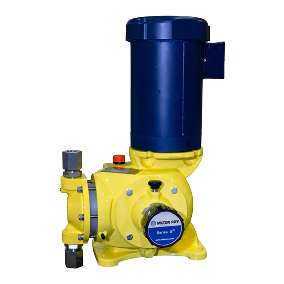
Page 4: I - 3. Operating Principle Of The Pump
Note: For further information on the automatic control Leak-tightness between the mechanical assembly and system, see the relevant specific manual. the liquid end is ensured by means of a bellows. Capacity adjustment is controlled either manually (by a stroke adjustment knob [4]) or automatically by a I - 3. -
Page 5: I - 5. Safety And Health Instructions
MECHANICAL ASSEMBLY 1 - 5. SAFETY AND HEALTH INSTRUCTIONS The mechanical assembly works on the principle of a variable eccentric. The personnel responsible for installing, operating and maintaining this equipment must become acquainted The rotational motion of the motor is transmitted by the worm [1] to the tangential gear [2] which is linked to an with, assimilate and comply with the contents of this eccentric system [3]. -
Page 6: Installation
PART II - INSTALLATION II - 1. HYDRAULIC INSTALLATION Note: The priming valve and the safety valve have no purpose if your pump is equipped with a 4-function valve. All the information concerning the hydraulic installation of a metering pump is detailed in a volume, «... - Page 7 Tank Injection nozzle Foot valve (equipped with a filter) Shutt-off valve Metering pump Filter Utilization Pulsation dampener 4-function valve* * In case of plastic liquid end only <22 l/h Provide for a safety valve on the discharge circuit in case of a stainless steel liquid end Fig.
-
Page 8: 5. Electrical Installation
II - 5. ELECTRICAL INSTALLATION For connection in SINGLE-PHASE mode, Mono see Figure 2.5d. CONNECTING THE MOTOR Replace the existing wires with those of your electrical Check the specifications of the motor and compare power supply. them with the voltage available on your installation before making connections. -
Page 9: Start Up
PART III - START UP III - 1. PROCEDURES BEFORE START III - 3. FAILURES ON START UP PROBLEMS WITH MOTOR Special care has to be taken for chemicals used in the process (acids, bases, oxiding/reducing solutions, ...). The motor runs with difficulty and heats up. See Figure 1.2a. -
Page 10: 4. Operation - Schedule Of Checks And Maintenance Operations
III - 4. OPERATION - SCHEDULE FOR The capacity is variable CHECKS AND MAINTENANCE OPERATIONS This problem may be due to particles from the piping which interfere with the operation of the valve The programme of checks and maintenance operations assemblies: clean the piping and the valve depends on the conditions in which the equipment is assemblies. - Page 11 MAINTENANCE SHEET Pump code D.M.R. internal no. : Liquid pumped Date of commissioning Service Operation Date Hours Remarks Fig. 3.4a : Model Maintenance Sheet III - 3...
-
Page 12: Routine Maintenance
PART IV - ROUTINE MAINTENANCE IV - 1. CHECKING THE PUMP CAPACITY This is a question of determining the curve representing the pump’s capacity according to its setting. Four measurements are sufficient (adjustment to 100 %,75 %, 50 % and 25 %). Place the foot valve in a calibrating chamber (graduated reservoir). -
Page 13: 3. Ordering Spare Parts
PROBLEMS WITH FLOW RATE A bearing is faulty. Provide for the replacement of either the « wheel - connecting rod » assembly [D], the « male eccentric » assembly [12] or the whole The pump produces no flow mechanical assembly [J] (see Part VI). ... -
Page 14: Preventive Maintenance - Annual Overhaul
PART V - PREVENTIVE MAINTENANCE ANNUAL OVERHAUL V - 1. SPARE PARTS REQUIRED FOR ANNUAL OVERHAUL Annual overhaul (after one year or 3,000 hours’ operation) involves the replacement of the following wear parts: Balls and seats kits or sets of cartridges (depending on model), ... -
Page 15: Corrective Maintenance
PART VI - CORRECTIVE MAINTENANCE VI - 1. LIST OF OTHER SPARE PARTS This completes the list given in Chapter V - 1 which covers the set of spare parts required for annual overhaul of the pump. Motor (with worm) ... -
Page 16: Servicing The Liquid End And The Liquid End Mounting Assembly
PART VII - SERVICING THE LIQUID END AND THE LIQUID END MOUNTING ASSEMBLY Carry out the procedures described below: in the order of the text in the case of annual overhaul (or 3,000 hours’ operation), except for the secondary diaphragm which has to be removed every two years (or 6,000 hours ’... - Page 17 VI – Assembly / Disassembly of the displacement chamber Draw: 1066167100D00 Position Torque ** Tools * Tools : [435] 5 N.m. BTR n°4 Provide a tool kit available for selling at the after sales department. [275] 3 N.m. Flat screwdriver [438A] [068] Thread lock...
- Page 18 Dwg-Nr 27360 PONT-SAINT-PIERRE 1066.167.100.D00 2 / 7 Tel : +33 (0)2 32 68 30 00 Fax : +33 (0)2 32 68 30 93 Propriété exclusive - Communication et reproduction interdites. All rights reserved - Copyright DOSAPRO MILTON ROY COMPANY SOLIDWORKS...
- Page 19 VI - Assembly / Disassembly of the liquid end CR - VR Draw: 1066167000D02 Position Torque ** Tools * Tools : [435B] 10 N.m. BTR n°6 Provide a tool kit available for selling at the after sales department. [02] Disassembly Assembly 1.
- Page 20 Dwg-Nr 27360 PONT-SAINT-PIERRE 1066.167.000.D02 2 / 2 Tel : +33 (0)2 32 68 30 00 Fax : +33 (0)2 32 68 30 93 Propriété exclusive - Communication et reproduction interdites. All rights reserved - Copyright DOSAPRO MILTON ROY COMPANY SOLIDWORKS...
- Page 21 VI - Filling / Change hydraulic oil Draw: 1066167100D03 Position Torque Tools * Tools : [Oil] Provide a tool kit available for selling at the after sales department. [Oil] Change Filling 1. Execute the procedure « Disassembly of the 1. Place a plug [B] like indicated on the drawing valve ».
- Page 22 Dwg-Nr 27360 PONT-SAINT-PIERRE 1066.167.100.D03 5 / 6 Tel : +33 (0)2 32 68 30 00 Fax : +33 (0)2 32 68 30 93 Propriété exclusive - Communication et reproduction interdites. All rights reserved - Copyright DOSAPRO MILTON ROY COMPANY SOLIDWORKS...
- Page 23 VI - Assembly / Disassembly of the valve Draw: 1066167100D04 Position Torque ** Tools * Tools : [013] Stop mechanical Flat key n°32 Provide a tool kit available for selling at the after sales department. [436] Stop mechanical + Flat key n°28 1/4 turn Disassembly Assembly...
- Page 24 Dwg-Nr 27360 PONT-SAINT-PIERRE 1066.167.100.D04 6 / 6 Tel : +33 (0)2 32 68 30 00 Fax : +33 (0)2 32 68 30 93 Propriété exclusive - Communication et reproduction interdites. All rights reserved - Copyright DOSAPRO MILTON ROY COMPANY SOLIDWORKS...
- Page 25 VII - Assembly / Disassembly of XR – XV liquid end Draw: 1066172000D02 Position Torque ** Tools * Tools : [435] 25 N.m. BTR n°8 Provide a tool kit available for selling at the after sales department. Disassembly Assembly 1. Place part [098] onto part [072B]. 1.
- Page 26 072B Date Dessiné / Drawn Vérifié / Checked 20/08/2014 B. PICARD D.DEPARROIS Ensemble doseur XR - XV XR - XV Liquid end assembly 1066172000D02 Propriété exclusive - communication interdites / All rights reserved - Copyright MiltonRoy compagny Coreldraw...
- Page 27 VII - Assembly / Disassembly CR – VR liquid end Draw: 1066172001D01 Position Torque ** Tools * Tools : [435] 25 N.m. BTR n°8 Provide a tool kit available for selling at the after sales department. Disassembly Assembly 1. Place part [098] onto part [072B]. 1.
- Page 28 Folio - Page Numéro Plan Dwg-Nr 27360 PONT-SAINT-PIERRE 1066172001D01 Tel : +33 (0)2 32 68 30 00 Fax : +33 (0)2 32 68 30 93 Propriété exclusive - Communication et reproduction interdites. All rights reserved - Copyright DOSAPRO MILTON ROY COMPANY SOLIDWORKS...
- Page 29 VI - Assembly / Disassembly of the check valve Drawing : 1066168000 Disassembly Assembly Note: Check that all parts are deburred. Position Torque Mechanical stop [021] 1. Unscrew the connections [021] 1. Fit the check valves (suction and discharge) like showed in the and remove the valve drawing.
- Page 30 Dwg-Nr 27360 PONT-SAINT-PIERRE 1066.168.000 1 / 1 Tel : +33 (0)2 32 68 30 00 Fax : +33 (0)2 32 68 30 93 Propriété exclusive - Communication et reproduction interdites. All rights reserved - Copyright DOSAPRO MILTON ROY COMPANY SOLIDWORKS...
-
Page 32: Servicing The Mechanical Assembly
PART VIII - SERVICING THE MECHANICAL ASSEMBLY Carry out the procedures described below: in the order of the text in the case of annual overhaul (or 3,000 hours’ operation), except for the secondary diaphragm which has to be removed every two years (or 6,000 hours ’ operation). VII - 1. - Page 33 Base Stroke locking device Housing Half stop ring Screw (base/housing) Stroke adjustment knob Tangential wheel Cover seal Connecting rod O-ring Spring Cover Metallic plate Motor (with worm) Bearing Screw Stop bearing Screw Screw Washer Crosshead Screw Male eccentric piece Stop * Female eccentric piece Stop O-ring...
- Page 34 O2. Reinstalling the « wheel - connecting rod » VIII - 2. DISMANTLING REINSTALLING assembly THE MECHANICAL ASSEMBLY 1. Where applicable, check that neither the spring (See Figure 8.2a.) [6] or the metallic plate [7] has been displaced during transportation: the spring must be at the M1.
- Page 37 Warranty claim shall not affect payment terms. INDUSTRIAL OWNERSHIP Information of this instruction manual are the exclusive property of MILTON ROY EUROPE. However, a license is granted to the Buyer of the good, or his final customer as defined by the Buyer within the order.
- Page 39 C/ Hierro, 33 Planta 3 Local 3 28045 Madrid ESPANA www.sdm-sistemas.com ITALIA / MALTA Milton Roy Italia Srl Tel.: +39 (0)39.65.78.505 - Fax: +39 (0)39 60.56.906 E-mail: quote.sp@miltonroy-europe.com Centro Direzionale Colleoni Via Paracelso, 16 Palazzo Andromeda Ingresso 1 20864 Agrate Brianza (MB) ITALIA www.miltonroy-europe.com...
Need help?
Do you have a question about the G Series and is the answer not in the manual?
Questions and answers