Table of Contents
Advertisement
The force in pump technology
INSTRUCTION MANUAL
FOR INSTALLATION
OPERATING, AND
MAINTENANCE.
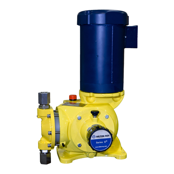
Dosing pump SERIE G ®
GM Liquid end DSD
This manual should be made available to the person responsible for installation, operating and
maintenance.
Translated version
DATE : 26 Juillet 2019
Rév 00
Réf. : 00
All rights reserved MILTON ROY EUROPE - Copyright COMPANY
MILTON ROY EUROPE / 10 Grande Rue - 27360 Pont-St-Pierre - FRANCE / Tel.: +33 (0)2.32.68.30.87 / mr14.contact@miltonroy.com
Advertisement
Table of Contents

Related Manuals for Milton Roy G Series


Summary of Contents for Milton Roy G Series
- Page 1 Translated version DATE : 26 Juillet 2019 Rév 00 Réf. : 00 All rights reserved MILTON ROY EUROPE - Copyright COMPANY MILTON ROY EUROPE / 10 Grande Rue - 27360 Pont-St-Pierre - FRANCE / Tel.: +33 (0)2.32.68.30.87 / mr14.contact@miltonroy.com...
-
Page 3: Table Of Contents
CONTENTS I - DESCRIPTION I - 1. Unpacking and storage I - 2. Description I - 3. Operating principle of the pump I - 4. Accessories I - 5. Safety and health instructions II - INSTALLATION II - 1. Hydraulic installation II - 2. - Page 4 GM001GB PART I - DESCRIPTION I - 2. DESCRIPTION I - 1. UNPACKING AND STORAGE UNPACKING The GM pump is a compact electromechanical metering pump that is life-lubricated with oil in a sealed housing, The packaging must be carefully examined on receipt in with capacity adjustment in operation or when stopped.
- Page 5 GM001GB I - 3. OPERATING PRINCIPLE OF THE PUMP See Figures 1.3b and 1.3c Fig. 1.3b : Setting to zero stroke Suction phase Discharge phase Fig. 1.3c : Setting to maximum stroke Worm Diaphragm Tangential wheel Stroke = two times the distance between (A) and (B) Eccentric Position at rear neutral point Connecting rod...
-
Page 6: Installation
GM002GB PART II - INSTALLATION II - 2. DRIP COLLECTION II - 1. HYDRAULIC INSTALLATION Provide for outlets so that any leak or drips can be All the information concerning the hydraulic installation easily drained off without any danger. This is especially of a metering pump is detailed in a volume, important in the case of harmful liquids. - Page 7 GM002GB Tank Injection nozzle Foot valve (equipped with a filter) Shutt-off valve Metering pump Filter Utilization Pulsation dampener Provide for a safety valve on the discharge circuit in case of a stainless steel liquid end Fig. 2.1a : Diagrams of typical installations...
- Page 8 GM002GB II - 5. ELECTRICAL INSTALLATION For connection in SINGLE-PHASE mode, Mono see Figure 2.5d. CONNECTING THE MOTOR Replace the existing wires with those of your electrical Check the specifications of the motor and compare power supply. them with the voltage available on your installation before making connections.
-
Page 9: Start Up
GM003GB PART III - START UP III - 1. PROCEDURES BEFORE III - 3. FAILURES ON START UP START UP PROBLEMS WITH MOTOR Special care has to be taken for chemicals used in the process (acids, bases, oxiding/reducing solutions, ...). The motor runs with difficulty and heats up. -
Page 10: Maintenance
GM004GB PART IV - ROUTINE MAINTENANCE IV-1. GENERAL For the sake of simplicity, the procedures described do not mention the washers fitted with fasteners (such as screws and nuts). Do not forget to reinstall washers after removing them. Verify that parts are undamaged before reinstalling. - Page 11 GM004GB MAINTENANCE SHEET Pump code S/N. : Liquid pumped Date of commissioning Service Operation Date Hours Remarks Fig. 3.4a : Model Maintenance Sheet...
- Page 12 GM004GB IV-3. ROUTINE MAINTENANCE The liquid end is unprimed: release the pressure on the discharge pipe and prime the liquid end, or check the leak-tightness of the suction circuit. CHECKING THE PUMP CAPACITY The balls of the valve assemblies are blocked by This is a question of determining the curve representing the particles: clean or replace the valve assemblies.
-
Page 13: Preventive Maintenance - Annual Overhaul
PART V - PREVENTIVE MAINTENANCE ANNUAL OVERHAUL V - 1. SPARE PARTS REQUIRED FOR ANNUAL OVERHAUL Annual overhaul (after one year or 3,000 hours’ operation) involves the replacement of the following wear parts: Balls and seats kits or sets of cartridges (depending on model), ... -
Page 14: Corrective Maintenance
PART VI - CORRECTIVE MAINTENANCE VI - 1. LIST OF OTHER SPARE PARTS This completes the list given in Chapter V - 1 which covers the set of spare parts required for annual overhaul of the pump. Motor (with worm) ... - Page 15 VI Assembly / Disassembly of the adjusting knob GM006GB Drawing 1066105100D05 rev00 Disassembly Assembly Position Torque value [700A] Mechanical stop 1. Remove the part [053] 1. Turn the part [056] in the negative direction until mechanical stop 2. Unscrew the screw [700A] 2.
- Page 17 VI-1 Assembly / Disassembly of the motor GM006-1GB Drawing 1066105100D06 rev00 Disassembly Assembly Position Torque value [435] Mechanical stop 1. Unscrew the screws [435] 1. Fit the parts [438],[081] 2. Remove the motor [028] 2. Fit the motor [028] 3. Remove the part [438] 3.
- Page 19 VI-2 Assembly / Disassembly of the mechanical assembly GM006-2GB Drawing 1066105100D03 rev00 Disassembly Assembly Position Torque value [435A] Mechanical stop 1. Unscrew the screws [435A] 1. Fit the parts [072],[438B],[438A] 2. Remove the whole from the housing 2. Oil the thread of the whole [A] 3.
- Page 21 V-2 Assembly / Disassembly of the secondary diaphragm GM005-2GB Drawing 1066105100D04 rev00 Disassembly Assembly Position Torque value Perform the following steps before this operation : [435A] 3 m.N [019] Mechanicam stop If the housing was drained, refill it (see Chapter LUBRICATION), with the pump being laid onto the 1.
- Page 23 VII - Assembly/dismantling of the displacement chamber 1/2 Drawing: 1066171000D00 Item Tightening Tools numbers torques** * Tools: [439] 5 N.m. Thread-locking Provide a tool kit (available to purchase from our after- adhesive No. 11 sales service). open-end wrench [435C] 3-4 N.m. No.
- Page 24 438D 438H 434B 438H 438F 435C 438E 438G 072E 435B 072B 435G Date Dessiné / Drawn Vérifié / Checked 19/11/2014 B. PICARD D.DEPARROIS Ensemble doseur XR - XV 435F XR - XV Liquid end assembly 1066171000D00 Propriété exclusive - communication interdites / All rights reserved - Copyright MiltonRoy compagny CORELDRAW Coreldraw...
- Page 25 VII - Assembly/dismantling of the displacement chamber 2/2 Drawing: 1066171000D01 Item Tightening Tools numbers torques** * Tools: [435] Strong block Provide a tool kit (available to purchase from our after-sales service). [435] 5 N.m. No. 4 Allen key [435G], 6.5 N.m. No.
- Page 26 438D 072B 435B 435E 435D 435G Date Dessiné / Drawn Vérifié / Checked 19/11/2014 B. PICARD D.DEPARROIS Ensemble doseur XR - XV 435F XR - XV Liquid end assembly 1066171000D01 Propriété exclusive - communication interdites / All rights reserved - Copyright MiltonRoy compagny CORELDRAW Coreldraw...
- Page 27 VII - Filling/draining the hydraulic oil Drawing: 1066171000D04 Item Tightening Tools numbers torques * Tools: [Oil] Provide a hydraulic start-up kit (available to purchase from our after-sales service). [Oil] View Dismantling View Assembly 1. Carry out the “Dismantling of the valve” 1.
- Page 28 072B Date Dessiné / Drawn Vérifié / Checked 19/11/2014 B. PICARD D.DEPARROIS ENS CHAMBRE HYDRAULIQUE DSD67 DSD67 Hydraulic Chambre Assy 106617100D04 Propriété exclusive - communication interdites / All rights reserved - Copyright MiltonRoy compagny Coreldraw...
- Page 29 VII - Assembly/dismantling of the valve Drawing: 1066171000D05 Item Tightening Tools numbers torques** * Tools: [013] Mechanical stop No. 32 open- Provide a hydraulic start-up kit (available to purchase end wrench from our after-sales service). [436] Mechanical stop + No. 28 open- quarter turn end wrench [432]...
- Page 30 438D 438C 072B Date Dessiné / Drawn Vérifié / Checked 19/11/2014 B. PICARD D.DEPARROIS ENS CHAMBRE HYDRAULIQUE DSD67 DSD67 Hydraulic Chambre Assy 106617100D05 Propriété exclusive - communication interdites / All rights reserved - Copyright MiltonRoy compagny Coreldraw...
- Page 31 VII - Assembly / Disassembly of the liquid end Draw : 1066172000D00 Disassembly Assembly Note: Clean and lubricate the part before the Position Torque assembling. [435] 30 N.m. 1. Carry out the process: "VII – Disassembly of 1. . Assemble the parts [098B] into the liquid end [021B] like the check valves".
- Page 32 Dwg-Nr 27360 PONT-SAINT-PIERRE 1 / 2 1066172000D00 Tel : +33 (0)2 32 68 30 00 Fax : +33 (0)2 32 68 30 93 Propriété exclusive - Communication et reproduction interdites. All rights reserved - Copyright DOSAPRO MILTON ROY COMPANY CORELDRAW...
- Page 33 VII - Assembly / Disassembly CR – VR liquid end Draw: 1066172001D01 Position Torque ** Tools * Tools : [435] 25 N.m. BTR n°8 Provide a tool kit available for selling at the after sales department. Disassembly Assembly 1. Place part [098] onto part [072B]. 1.
- Page 34 Folio - Page Numéro Plan Dwg-Nr 27360 PONT-SAINT-PIERRE 1066172001D01 Tel : +33 (0)2 32 68 30 00 Fax : +33 (0)2 32 68 30 93 Propriété exclusive - Communication et reproduction interdites. All rights reserved - Copyright DOSAPRO MILTON ROY COMPANY SOLIDWORKS...
- Page 35 VI - Assembly / Disassembly of the check valve Drawing : 1066168000 Disassembly Assembly Note: Check that all parts are deburred. Position Torque Mechanical stop [021] 1. Unscrew the connections [021] 1. Fit the check valves (suction and discharge) like showed in the and remove the valve drawing.
- Page 36 Dwg-Nr 27360 PONT-SAINT-PIERRE 1066.168.000 1 / 1 Tel : +33 (0)2 32 68 30 00 Fax : +33 (0)2 32 68 30 93 Propriété exclusive - Communication et reproduction interdites. All rights reserved - Copyright DOSAPRO MILTON ROY COMPANY SOLIDWORKS...
- Page 37 DOS ESTADOS MEMBROS RELATIVAS ÀS MÁQUINAS. Nós, MILTON ROY EUROPE - 27360 Pont Saint Pierre – FRANCE , declaramos que o material designado em seguida : está em conformidade com a directiva "máquinas" sob reserva que a instalação, utilização e manutenção sejam efectuadas seguindo as regras da arte e segundo as prescrições da nota de instruções.
- Page 38 DIREKTIV FRÅN RÅDET, DEN 17 KAN 2006 (2006/42 EC) RÖRANDE NÄRMANDE AV MEDLEMSSTATERNAS LAGSTIFTNINGAR FÖR MASKINER. Vi, MILTON ROY EUROPE - 27360 Pont Saint Pierre – FRANKRIKE, intygar att nedan beskriven utrustning : överensstämmer med "maskin"-direktivet under förutsättning att den installareas, används och underhålls enligt konstens regler och enligt de beskrivningar som ges i användarinstruktionen.
- Page 39 Warranty claim shall not affect payment terms. INDUSTRIAL OWNERSHIP Information of this instruction manual are the exclusive property of MILTON ROY EUROPE. However, a license is granted to the Buyer of the good, or his final customer as defined by the Buyer within the order.
- Page 41 C/ Hierro, 33 Planta 3 Local 3 28045 Madrid ESPANA www.sdm-sistemas.com ITALIA / MALTA Milton Roy Italia Srl Tel.: +39 (0)39.65.78.505 - Fax: +39 (0)39 60.56.906 E-mail: sergio.testa@miltonroy.com Centro Direzionale Colleoni Via Paracelso, 16 Palazzo Andromeda Ingresso 1 20864 Agrate Brianza (MB) ITALIA www.miltonroy-europe.com...
Need help?
Do you have a question about the G Series and is the answer not in the manual?
Questions and answers