
Related Manuals for Federal Signal Corporation 151XST Series


Summary of Contents for Federal Signal Corporation 151XST Series
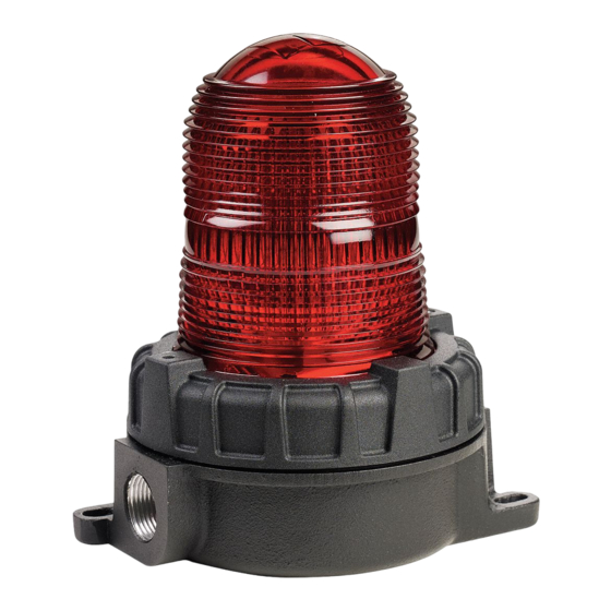
- Page 1 Model 151XST Series Strobe Light for Use in Hazardous Conditions Installation and Maintenance Manual 256822J rançais....page 21 REV. J 613 español....página 43 Printed in U.S.A.
- Page 2 Seller within thirty days after Buyer learns of the defect or such claim shall be deemed waived. Industrial Systems 2645 Federal Signal Drive • University Park, IL 60484-3167 Tel: 708-534-4756 • Fax: 708-534-4852 Email: elp@federalsignal.com • www.federalsignal-indust.com © 2013 Federal Signal Corporation. All rights reserved.
-
Page 3: Table Of Contents
Contents Safety Messages to Installers ............5 An Overview of the 151XST Series ..........6 Unpacking the Light ................7 Pipe-Mounting the Beacon (151XST) ..........9 Surface-Mounting the Beacon (151XST-S) ........10 Wiring the Beacon ................11 Wiring the AC Models............12 Wiring the DC Models ............ - Page 4 Contents Figures Figure 1 Pipe-mounted beacon ............10 Figure 2 Surface-mounted beacon ..........11 Figure 3 Cross section of beacons ..........13 Figure 4 Normal (A) and darkened (B) flash tube ......17 Models 151XST and 151XST-S...
-
Page 5: Safety Messages To Installers
Installation and Maintenance Instructions Safety Messages to Installers It is important to follow all instructions shipped with this product. This device is to be installed by a trained electrician who is thoroughly familiar with the National Electrical Code and/or Canadian Electrical Code and will follow the NEC and/or CEC Guidelines as well as all local codes. -
Page 6: An Overview Of The 151Xst Series
Failure to follow all safety precautions and instructions may result in property damage, serious injury, or death. An Overview of the 151XST Series Federal Signal’s Model 151XST hazardous location strobe light provides 80 high-intensity flashes per minute. This warning light is available in 12-24 Vdc, 120 Vac and 240 Vac, 50/60 Hz. -
Page 7: Unpacking The Light
Installation and Maintenance Instructions Unpacking the Light EXPLOSION HAZARD—Damaged domes can lead to explosions that could result in serious injury or death. After unpacking the beacon, examine it for damage that may have occurred in transit. If the beacon has been damaged, do not attempt to install or operate it. -
Page 8: Table 3 Flash Rate And Candelas
Installation and Maintenance Instructions Table 3 Flash rate and candelas Model Flash Rate Candela per Minute Peak 151XST(-S) 012-024__ 520,000 151XST(-S)-120__ 520,000 151XST(-S)-240__ 520,000 __ Indicates color: (A) amber, (B) blue, (C) clear, (G) green, (M) magenta or (R) red. Peak candela is the maximum light intensity generated by a flashing light during its light phase. -
Page 9: Pipe-Mounting The Beacon (151Xst)
Installation and Maintenance Instructions Pipe-Mounting the Beacon (151XST) EXPLOSION HAZARD—To reduce the risk of fire or explosion, do not install the beacon in a hazardous location if the operating temperature exceeds the hazardous atmosphere’s ignition temperature. Before proceeding, consult the product nameplate and determine the operating temperature of the beacon. -
Page 10: Surface-Mounting The Beacon (151Xst-S)
Installation and Maintenance Instructions Figure 1 Pipe-mounted beacon 151XST LIGHT ASSEMBLY SET SCREW 3/4" NPT PIPE 290A6904 Surface-Mounting the Beacon (151XST-S) To surface mount the beacon: See Figure 2. Use the mounting base as a template to mark the location of the two mounting holes. Drill a 9/32-inch (7.143 mm) hole at each mark. -
Page 11: Wiring The Beacon
MOUNTING SURFACE 290A6905 Wiring the Beacon The Model 151XST Series Beacon should be installed per the NEC or CEC, STATE and LOCAL CODES. Alternate installation locations and/or orientations should only be performed with the approval of the authority having jurisdiction. In addition, the unit can be mounted using an optional ceiling mount or optional wall mount. -
Page 12: Wiring The Ac Models
Installation and Maintenance Instructions SHOCK HAZARD—To avoid electrical shock hazards, do not connect wires while power is applied. EXPLOSION HAZARD—Do not disconnect the beacon while the circuit is live or unless the area is known to be free of ignitable concentrations. Keep the beacon tightly closed when in operation. -
Page 13: Figure 3 Cross Section Of Beacons
Installation and Maintenance Instructions 6. Connect power to the beacon and test it for proper operation. Figure 3 Cross section of beacons 165.6 mm (6.52 in) MODEL 151XST-S DOME GUARD (INCLUDED) GLASS DOME ASSY. FLASH TUBE 207.8 mm (8.18 in) ALUMINUM GASKET BASE... -
Page 14: Wiring The Dc Models
Installation and Maintenance Instructions Wiring the DC Models The DC units have two 24-inch leads, one black and one red. To wire the DC beacon: 1. Ensure that power is off. 2. Remove the threaded dome assembly by twisting it counterclockwise. - Page 15 Installation and Maintenance Instructions • Never alter the unit in any manner. Safety of the unit may be affected if additional openings or other alterations are made to the internal components or housing. • The nameplate should NOT be obscured, as it contains cautionary and/or other information of importance to maintenance personnel.
-
Page 16: Replacing The Flash Tube
Installation and Maintenance Instructions SHOCK HAZARD—High voltages are present inside the light assembly. Wait at least 5 minutes after shutting off the power before servicing this unit. Establishing a regular maintenance and inspection schedule extends the life of the Model 151XST and ensures safety. For service, support, or replacement parts, see pages 19 and 20. -
Page 17: Replacing The Printed Circuit Board (Pcb)
Installation and Maintenance Instructions 6. Test the beacon for proper operation. Figure 4 Normal (A) and darkened (B) flash tube 290A7396 Replacing the Printed Circuit Board (PCB) To replace the PCB: 1. Disconnect the power to the beacon and wait at least 5 minutes to allow all capacitors to discharge. -
Page 18: Cleaning The Fixture
Installation and Maintenance Instructions 5. Secure the new circuit board to the housing with the screw removed in step 2. 6. Install the new flash tube in the socket. Ensure that the flash tube is fully seated in the socket. 7. -
Page 19: Getting Repair Service Or Technical Assistance
Installation and Maintenance Instructions Getting Repair Service or Technical Assistance Products returned for repair require a Return Authorization form from your local distributor or from Federal Signal. To obtain repair service or technical assistance from Federal Signal, call 708-534-4756 or 877-289-3246. For instruction manuals and information on related products, visit: http://www.federalsignal-indust.com Ordering Accessories and Replacement Parts... -
Page 20: Returning The Product For Credit
Installation and Maintenance Instructions Table 6 Accessory Description Model Hazardous Location Wall-Mount Bracket LHWB* * Cannot be used in Class II, Division 1 applications. NEMA 4X and IP66 rated when used with the appropriate conduit fittings. Returning the Product for Credit Product returns for credit require a return authorization from your local distributor prior to returning the product to Federal Signal.
Need help?
Do you have a question about the 151XST Series and is the answer not in the manual?
Questions and answers