
Related Manuals for Extron electronics AVTrac 42-122-xx


Summary of Contents for Extron electronics AVTrac 42-122-xx
-
Page 1: Installation Guide
Installation Guide AVTrac ® International/Universal Models Floor-mount Raceway with Modular AAP Connectivity for A/V, Data, and Power 68-1562-01 Rev. A 09 08... - Page 2 Precautions Safety Instructions • English This symbol is intended to alert the user of important operating and maintenance (servicing) instructions in the literature provided with the equipment. This symbol is intended to alert the user of the presence of uninsulated dangerous voltage within the product’s enclosure that may present a risk of electric shock.
- Page 3 Introduction Overview This manual describes the AVTrac AVTrac Floor System Low-profile Raceway System AVTrac is a low-profile raceway system designed to safely and discretely run power, data, and A/V cables from a wall to a table, podium, or other furniture. The raceway system mounts directly onto the concrete floor and underneath the carpet.
-
Page 4: Kit Contents
Kit Contents The AVTrac Kit is shipped in two boxes. • Box 1 contains the track and ramp components. • Box 2 contains the connectivity box, the conduit and accessory components. Check the contents of each box to ensure all items are present. Plastic Template (1) Checklist for contents of box 1 8' (2.44 m) aluminum base track (1) -
Page 5: Table Of Contents
Kit Contents Check the contents of each box to ensure all items are present. Installation Guide (1) Connectivity Box (1) End Ramps (2) Checklist for contents of box 2 Connectivity box (1) with 6/32" nut (1) to secure AC power module †... -
Page 6: Before Getting Started
Before Getting Started Planning AVTrac can be installed before new carpeting is fitted or retrofitted under pre-existing carpet. It can also be installed in new construction before the wall and carpeting is in place. Retrofitting the track in a space with existing carpeting and furniture requires some extra preparation to remove the carpet and prepare the floor for laying the track. - Page 7 Room Considerations Determine the A/V requirements for the room. Extron provides a complete range of AAPs that can be purchased separately to provide fully customizable central connectivity. Select the best configuration for existing furniture, equipment, cables and the AVTrac. It may help to mark the position of the track using a marker pen or tape.
- Page 8 Before Getting Started, Tools and Equipment Required for Installation Almost everything you need to install your AVTrac system has been included. You will need some basic tools and materials depending on the facility and requirements. You can visit www.extron.com for a full range of cables and components for populating the connectivity box. N All structural steps and electrical installation should be performed by qualified personnel in accordance with local and national building codes and/or local and national electrical codes.
- Page 9 Installation By this point you must have decided exactly where the AVTrac will be installed, checked the contents of the kit, and gathered the tools that you will need. Extron recommends consulting a carpeting expert before removing the carpet. Determine whether the installation will be in new construction, under pre-existing carpet tiles or under pre-existing carpet rolls, and follow the appropriate instructions.
- Page 10 Installation This manual shows an AVTrac installation with cables being run inside a drywall cavity. If the cables from the AVTrac system will not be run inside a drywall cavity, ignore this section and go to Step 3 (Track) on the next page. To run cables from the AVTrac system inside a drywall cavity, follow these instructions: If necessary, remove the baseboard from the bottom of the wall and mark where the AVTrac will abut the...
- Page 11 Installation Measure and cut the track pieces to the desired length. N If the track is to be cut, the base track must be 10” (25.4 cm) longer than the cover track. This is the length of the connectivity box, which sits on the base track but not on the cover track (see figure below right).
- Page 12 Installation Drill mounting holes in the shallow grooves of the base track and side ramps using a 1/4" or 6 mm bit for drilling metal (not supplied). N Mounting holes must be a maximum of 3' (91 cm) apart and one must be within 6" (15.2 cm) of each end of the track.
- Page 13 Lay the base track on the floor in the prepared location. Mate the tabs in the side ramps with the grooves in the base track, and place the end ramps in position at the end of the track furthest from the wall.
-
Page 14: 3/16" Masonry Screws
Installation By this point, the base track, side ramps and end ramps must be securely fastened to the floor. To attach the connectivity box to the base track, follow these instructions: Reposition the connectivity box, in the correct orientation, over the pre-drilled holes in the base track (see instruction 3-3). - Page 15 Installation By this point, the connectivity box must be securely fastened to the floor. If the AVTrac system does not include the AC power module, ignore this section. To attach the AC power module, follow these instructions: Switch off all electrical power before connecting the AC conduit to a junction box, and keep power off until installation is complete.
- Page 16 Installation The AC power module must be positioned under the triple AAP socket that is closest to the track. Seat the power module on the stud in the connectivity box. Slide the power module side tabs into the slots on the side of the connectivity box.
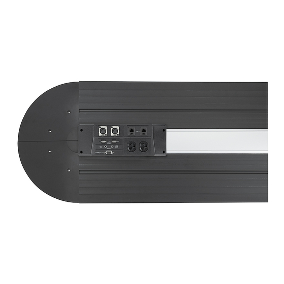
- Page 17 Installation At this point, the track, ramps and connectivitly box must all be securely in place, and the AC power module must be attached to the connectivity box and connected to an AC junction box. To attach the Architectural Adapter Plates (AAPs), follow these instructions: Select up to seven AAPs to fill the remaining spaces in the cover of the connectivity box.
- Page 18 Installation At this point, the track and connectivity box must be secured to the floor, the electrical power must be connected, and the AAP sockets must be populated. To complete the installation of the AVTrac, follow these instructions: Lay the cables and power cords flat against the base track.
- Page 19 Glue or tape the carpet to the floor and side ramps. N Do not use the supplied tape to attach the carpet to the ramp. The tape is intended only for the attaching the rubber inlay strip to the cover track. Using the provided template, trim the wall baseboard to fit snugly around the track.
- Page 20 Installation The installed AVTrac safely and discretely runs power, data, and A/V cables from a wall to a table, podium, or other furniture. AVTrac installed AVTrac • Installation Step 7: Finishing up cont’d...
-
Page 21: End Ramps
Reference Material Specifications General Power (pass-through) ... 250 VAC, 50/60 Hz, 10 A (max.) Mounting options Track system (track and ramps) Mountable on base flooring, beneath the finished carpet Connectivity box ... Mountable through the metal track, onto base flooring Optional AAP plates/devices Mountable in the two double-space and two triple-space Architectural Adapter Plate (AAP) openings in the connectivity box... - Page 22 Reference Material, AVTrac 480C (47.55 cm) 9.36” (23.77 cm) 1.09" (2.61 cm) 7.50" (19.05 cm) AVTrac 480R 9.36” (23.77 cm) .95" (2.41 cm) 7.50" (19.05 cm) AVTrac • Reference Material End Ramp 18.72” Connectivity (AAP) Box 10.00” (25.4 cm) 8’-0” (2.438 m) TOP VIEW 2.91"...
-
Page 23: Box
4.91" (12.47cm) 3.55" (9.02 cm) SIDE VIEW Connectivity box 10.00" (25.4 cm) 3.55" (9.02 cm) TOP VIEW 10.00" (25.4 cm) 4.91" (12.47 cm) .67" (1.70 cm) 2.98" (7.57 cm) END VIEW AVTrac • Reference Material... - Page 24 Reference Material, Universal AC Compatibility Guide The Extron Universal AC Outlet allows a number of different AC plugs to be used in the AVTrac , HSA, and Cable Cubby ™ table on this card to see if your plug type is compatible with the Universal AC Outlet. In some countries there may be polarity differences.
- Page 25 Optional Accessories Please consult the Extron Web site (www.Extron.com) or catalog for a complete description of each item. Track Accessories Accessory AVTrac 4 Track Extension Kit for Carpet Inlay AVTrac 4 Track Extension Kit for Rubber Inlay AVTrac Rough-In Adapter AVTrac Wall Trim Plate AVTrac Raceway Transition (Wiremold) AVTrac Raceway Transition (Euro Channel)
- Page 26 Reference Material, cont’d AVTrac • Reference Material...
- Page 27 Extron Electronics warrants this product against defects in materials and workmanship for a period of three years from the date of purchase. In the event of malfunction during the warranty period attributable directly to faulty workmanship and/or materials, Extron Electronics will, at its option, repair or replace said products or components, to whatever extent it shall deem necessary to restore said product to proper operating condition, provided that it is returned within the warranty period, with proof of purchase and description of malfunction to:...
-
Page 28: Ac Power Module
Quick Installation Checklist Installation of the AVTrac can be divided into six main sections: Step 1 — Before Getting Started Decide where the Track will be placed (pages 4 and 5) and, if necessary, prepare † the site. Open the two boxes containing the AVTrac kit and identify all the items provided †...
Need help?
Do you have a question about the AVTrac 42-122-xx and is the answer not in the manual?
Questions and answers