Advertisement
Master Forge & M Design
trademark of LF, LLC. All rights reserved.
WARNING
Improper installation,
adjustment, alteration, service
or maintenance can cause
injury or property damage.
Read this instruction manual
thoroughly before installing or
servicing this equipment.
WARNING
1. Do not store or use gasoline or
other flammable vapors and
liquids in the vicinity of this or
any other appliance.
2. An LP tank not connected for
use should not be stored in the
vicinity of this or any other
appliance.
DANGER
If you smell gas:
1. Shut off gas to the appliance.
2. Extinguish any open flames.
3. Open the lid.
4. If the odor continues, keep
away from the appliance and
immediately call your gas
supplier or fire department.
WARNING
For Outdoor Use Only
ATTACH YOUR RECEIPT HERE
Serial Number
Questions, problems, missing parts? Before returning to your retailer, call our
customer service department at 1-800-963-0211, 8:00 a.m. to 6:00 p.m., EST,
Monday-Thursday, 8:00 a.m. to 5:00 p.m., EST, Friday.
AB13567
®
is a registered
○
R
Purchase Date
1
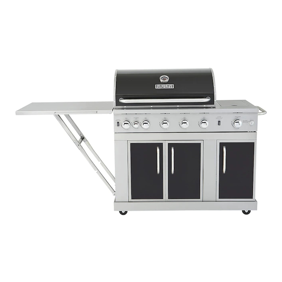
ITEM #0006554
5-BURNER GAS GRILL
MODEL #3218LTN
Español p. 53
Lowes.com/masterforge
Advertisement

Related Manuals for Master Forge 3218LTN


Summary of Contents for Master Forge 3218LTN
- Page 1 ITEM #0006554 5-BURNER GAS GRILL MODEL #3218LTN ○ ® Master Forge & M Design is a registered Español p. 53 trademark of LF, LLC. All rights reserved. WARNING Improper installation, adjustment, alteration, service or maintenance can cause injury or property damage.
-
Page 2: Table Of Contents
TABLE OF CONTENTS Safety Information ........................3 Safety Tips……………………………………………………………………………………………5 Package Contents .........................6 Hardware Contents .......................8 Preparation ..........................8 Assembly Instructions ......................9 Cooking with Gas ........................24 Operating Instructions ......................31 Care and Maintenance ......................38 Troubleshooting ........................46 Warranty ..........................49 Replacement Parts List .......................50 Lowes.com/masterforge... -
Page 3: Safety Information
SAFETY INFORMATION Please read and understand this entire manual before attempting to assemble, operate or install the product. If you have any questions regarding the product, please call customer service at 1-800-963-0211, 8:00 am to 6:00 pm, EST, Monday- Thursday, 8:00 a.m. - Page 4 SAFETY INFORMATION 15 The pressure regulator for LP-gas grill is set for 11-in. water column (WC). Natural gas grill provides a hose assembly which includes a quick-disconnect device. But no pressure regulator. The LP pressure regulator or the Natural gas hose assembly must be used. Replacement pressure regulators and hose assemblies must be those specified in the part list.
-
Page 5: Safety Tips
SAFETY TIPS Never pull your grill. Always push it. Never move your grill while it is in operation or still hot. Always use a protected hand when cleaning the grid surface after the post-heating period and when closing the propane tank valve. Use a covered hand during the grilling period. -
Page 6: Package Contents
PACKAGE CONTENTS Lowes.com/masterforge... - Page 7 PACKAGE CONTENTS Part Description Quantity Part Description Quantity Burner Box Locking Caster Heat Tent Transformer Main Grid Main Bottom Panel Warming Rack Caster Sear Burner Grid Right Door Sear Burner Right Skirt Drip Tray Grill Handle Main Beam Battery Center Door Left Rear Panel Left Door Right Rear Panel...
-
Page 8: Hardware Contents
HARDWARE CONTENTS 5/32-32 x 3/8 in. 1/4-20 x 5/8 in. Flat Head 5/32-32 3/16-24 x 1/2 in. Screw Screw x 1/2 in. Screw Screw Qty. 6 Qty. 2 Qty. 57 Qty. 8 Qty. 4 Wrench Qty. 1 PREPARATION Before beginning assembly of product, make sure all parts are present. Compare parts with package contents list and diagram above. -
Page 9: Assembly Instructions
ASSEMBLY INSTRUCTIONS WARNING: The grill should be assembled and placed on a flat level surface. Compare the parts and hardware with the list and diagrams. Do not attempt assembly if any part is missing or damaged. 1. Align the casters (Q and T) with the holes of the main bottom panel (S). - Page 10 ASSEMBLY INSTRUCTIONS 3. Align the holes in the left rear panel (I) with the holes in the main bottom panel (S) and insert the screws (BB) into the aligned holes. (Fig. 3) Hardware Used 1/4-20 x 5/8 in. Screw Note: Do not tighten the screws completely. Leave at least one full turn on each.
- Page 11 ASSEMBLY INSTRUCTIONS 5. Align the holes in the Center Panel (K) with the holes in the main bottom panel (S) and insert the screws (BB) into the aligned holes and tighten them. (Fig. 5) Note: Do not tighten the screws completely. Leave at least one full turn on each.
- Page 12 ASSEMBLY INSTRUCTIONS 7. Slide the tank ring bracket (M) to the end of the patented safety tank ring (AC) as shown. Then align the holes in the ring bracket with left rear panel (I), insert screws (BB) into the holes from outside of grill, and then tighten completely.
- Page 13 ASSEMBLY INSTRUCTIONS 9. For right panel (P), there are six screws (BB) to connect to the right rear panel (J) and the main bottom panel (S), three in the rear and three inside the cabinet. Insert the screws into the aligned holes and tighten them. The three screws inside the cabinet should be engaged first.
- Page 14 ASSEMBLY INSTRUCTIONS 11. For left skirt (Z), there are four screws (BB) to connect to the left panel (AB) and main bottom Tab A panel (S), two in the left panel and two inside the cabinet. Make sure the tab A is locked in place. Insert the screws into the aligned holes and tighten them.
- Page 15 ASSEMBLY INSTRUCTIONS 13. Align the holes in the hinges of the two doors (X and Y) with the two skirts (V and Z), insert flat head screws (DD) into the holes, and then tighten. (Fig. 13) Hardware Used Flat Head 5/32-32 x 1/2 in.
- Page 16 ASSEMBLY INSTRUCTIONS 15. For right door (U), insert bottom hinge pin into hole in the main bottom panel (S). Push down on top hinge pin to insert into hole on the main beam (W). Loosen the screws holding the magnets to center panel (K).
- Page 17 ASSEMBLY INSTRUCTIONS 17. Slide the main burner drip tray (AF) between the drip tray support (AE) from the back of grill. (Fig. 17) 18. Attach the battery box (AG) to the left panel (AB) with screws (CC) and nuts (AA). (Fig.
- Page 18 ASSEMBLY INSTRUCTIONS 19. Take the pressure regulator out from under the burner box (A). Then lift the burner box (A) onto the cabinet, making sure that the gas pressure regulator is in the cabinet, then position burner box on the cabinet by aligning the four tabs on top of the cabinet with the holes in the burner box.
- Page 19 ASSEMBLY INSTRUCTIONS 21. Connect the connector which is on the end of the light wire from step 20 to the transformer (R). Push the connector to mate firmly with the transformer. Then, screw and tighten the cap on the connector. (Fig. 21) connector 22.
- Page 20 ASSEMBLY INSTRUCTIONS 24. Loosen the eight screws in the side panel of burner box and the bottom panel three turns. This will allow for quick assembly of the buffet table. (Fig. 24) 25. Align the holes of the hinges in the buffet table (AD) with the holes in the burner box and the main bottom panel.
Need help?
Do you have a question about the 3218LTN and is the answer not in the manual?
Questions and answers
Where does the wire off the transformer attach to?
The wire from the transformer attaches to the connector on the end of the light wire that comes from the burner box. The connector is pushed firmly onto the transformer, and then the cap on the connector is screwed and tightened.
This answer is automatically generated