Advertisement
Master Forge & M Design® is a registered
trademark of LF, LLC.
All rights reserved.
WARNING
Improper installation, adjustment,
alteration, service or maintenance can
cause injury or property damage. Read
this instruction manual thoroughly before
installing or servicing this equipment.
WARNING
1. Do not store or use gasoline or other
flammable vapors and liquids in the
vicinity of this or any other appliance.
2. An LP tank not connected for use
should not be stored in the vicinity of this
or any other appliance.
DANGER
If you smell gas:
1. Shut off gas to the appliance.
2. Extinguish any open flames.
3. Open the lid.
4. If the odor continues, keep away from
the appliance and immediately call your
gas supplier or fire department.
WARNING
For Outdoor Use Only
ATTACH YOUR RECEIPT HERE
Serial Number
Questions, problems, missing parts? Before returning to your retailer, call our
customer service department at 1-800-963-0211, 8:00 a.m. – 8:00 p.m., EST,
Monday - Friday.
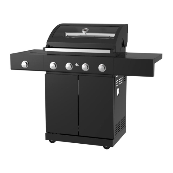
AB17891
4-BURNER GAS GRILL
Purchase Date
1
ITEM #0837902
MODEL #BG2294B-LB
Français p. 38
Advertisement
Table of Contents

Related Manuals for Master Forge BG2294B-LB


Summary of Contents for Master Forge BG2294B-LB
- Page 1 ITEM #0837902 4-BURNER GAS GRILL MODEL #BG2294B-LB Master Forge & M Design® is a registered Français p. 38 trademark of LF, LLC. All rights reserved. WARNING Improper installation, adjustment, alteration, service or maintenance can cause injury or property damage. Read this instruction manual thoroughly before installing or servicing this equipment.
- Page 2 WARNING DANGER If you smell gas: 1. Do not store or use gasoline or other flammable liquids or vapors in the vicinity 1. Shut off gas to the appliance. of this or any other appliance. 2. Extinguish any open flame. 3.
-
Page 3: Table Of Contents
TABLE OF CONTENTS Safety Information ........................ 4 Package Contents ....................... 6 Hardware Contents ......................8 Assembly Instructions ......................9 Natural Gas Conversion ..................... 17 Operating Instructions ......................22 Care and Maintenance....................... 31 Troubleshooting ......................... 33 Warranty ..........................34 Exploded View ........................35 Replacement Parts List ...................... -
Page 4: Safety Information
SAFETY INFORMATION Please read and understand this entire manual before attempting to assemble, operate or install the product. 1. The installation of this appliance must conform with local codes or, in the absence of local codes, with either the National Fuel Gas Code, ANSI Z223.1/NFPA 54, or Natural Gas and Propane Installation Code, CSA/CGA-B149.1. - Page 5 SAFETY INFORMATION 16. The cylinder used must include a collar to protect the cylinder valve. 17. Do not store a spare LP-gas cylinder under or near this appliance. 18. Never fill the cylinder beyond 80 percent full. 19. If the information in “17” and “18” is not followed exactly, a fire causing death or serious injury may occur.
-
Page 6: Package Contents
PACKAGE CONTENTS... - Page 7 PACKAGE CONTENTS PART DESCRIPTION PART DESCRIPTION Firebox Assembly Hinge Drip Tray Reinforcing Plates Grease Cup Left Drip Tray Support Warming Rack Door Beam Cooking Grate Back Board Flame Tamer Right Drip Tray Support Right Shelf Right Side Panel Right Shelf Support Lockable Castor Side Burner Castor...
-
Page 8: Hardware Contents
HARDWARE CONTENTS M6x16 mm M6x12 mm M4x12 mm M4x8 mm Screw Screw Screw Screw Qty.28 Qty.27 Qty.24 Qty.11 Plastic Washer Flat Washer Spring Washer Qty.1 Qty.1 Qty.20 Qty.20 Battery Qty.1 PREPARATION Before beginning assembly of product, make sure all parts are present. Compare parts with package contents list and hardware contents list. -
Page 9: Assembly Instructions
ASSEMBLY INSTRUCTIONS IMPORTANT: ASSEMBLE ON FLAT AND SOFT SURFACE TO AVOID SCRATCHING. 1. Attach Castors (W) to the front of the Bottom Panel (X) as shown. Attach Lockable Castors (V) to the back of the Bottom Panel as shown. Hardware Used M6x16 mm Screw 6 Flat Washer 6 Spring Washer... - Page 10 ASSEMBLY INSTRUCTIONS 4. Attach the Front Beam (R) to the Left Side Panel (M) and Right Side Panel (U). Attach one of the Reinforcing Plates (P) to the Left Side Panel and Bottom Panel and the other to the Right Side Panel and Bottom Panel.
- Page 11 ASSEMBLY INSTRUCTIONS 7. Attach Door Hinges (O) and Hinge Spacers (N) to Left & Right Side Panels as shown. Note: DO NOT tighten the screws of this step now. Hardware Used M4x12 mm Screw 8. Attach Left Door (Z) and Right Door (Y) to Door Hinges, then tighten all of the screws, including the screws in last step.
- Page 12 ASSEMBLY INSTRUCTIONS 10. Attach Firebox Assembly (A) to the top of the cabinet assembly and fasten the screws and washers as shown. Hardware Used M6x16 mm Screw 6 Flat Washer 6 Spring Washer 11. Remove the trivet from the Side Burner Assembly (I), then untighten the screws and remove the side burner as shown.
- Page 13 ASSEMBLY INSTRUCTIONS Attach Side Burner assembly onto firebox. 13. Attach two pcs Screws (AA) into the upper two holes on left side of firebox. Leave the 0.2 inches screw heads protruding approximately 0.2 inches. Hardware Used M6x16 mm Screw 14. Hang the Side Burner Assembly on the two screws attached in the previous step.
- Page 14 ASSEMBLY INSTRUCTIONS 16. Re-assemble the side burner and trivet removed in Step 11 as shown. Insert the ignition wire as shown below. Attach Right Side Shelf onto firebox. 0.2 inches 17. Attach 2pcs Screws (AA) into the upper two holes on Right side of firebox. Leave the screw heads protruding approximately 0.2 inches.
- Page 15 ASSEMBLY INSTRUCTIONS 19. Insert Flame Tamer (F), Cooking Grates (E), and Warming Rack (D). Place AA battery (II) into the electronic igniter with the positive (+) end facing out. Hardware Used AA Battery 20. The grill is now assembled.
-
Page 16: Natural Gas Conversion
NATURAL GAS CONVERSION PREPARATION: Before beginning conversion, make sure all parts are present. If any part is missing or damaged, do not attempt to convert. Please have your owner’s manual and part number available for reference, and contact customer service 1-800-963-0211 for replacement parts. 1. - Page 17 NATURAL GAS CONVERSION IMPORTANT: After your grill is converted to natural gas, the working pressure for natural gas is 7 in. water column (WC). Gas pressure is affected by gas line size and the length of gas line run from house.
- Page 18 NATURAL GAS CONVERSION WARNING: Place the grill on a flat, level surface. Before the conversion, make sure all control knobs are in the OFF position, LP tank valve is closed, and tank is disconnected from regulator and removed from grill. 21.
- Page 19 NATURAL GAS CONVERSION 23. Loosen the screw from LPG setting, rotate the shutter opening counterclockwise, adjusting it from LP setting to NG setting. Re-tighten the screw into NG setting for securing the air shutter opening. 24. Reinstall the main burners and cotter pins. Make sure to engage the burner valves as shown.
- Page 20 NATURAL GAS CONVERSION 26. Remove the old orifice using the orifice removal tool. Tighten the new orifice. 26.1. Unscrew the pre-assembled screw as shown, rotate the air shutter opening clockwise, adjusting it from the LPG setting to the NG setting. Replace the pre-assembled screw, thus securing the air shutter opening.
-
Page 21: Operating Instructions
OPERATING INSTRUCTIONS LIQUID PROPANE GAS INSTALLATION Gas grills that are set to operate with Liquid Propane Gas come with a high capacity hose and regulator assembly. (Note: Only use the pressure regulator and hose assembly supplied with the grill or a replacement pressure regulator and hose assembly specified by the manufacturer). - Page 22 OPERATING INSTRUCTIONS 3. Check the tank valve to ensure it has proper external mating threads to fit the hose and regulator assembly provided (Type 1 connection per ANSI Z21.58-2015 CSA 1.6-2015). LP cylinder valve must have: Type 1 outlet compatible with regulator or grill. 4.
- Page 23 OPERATING INSTRUCTIONS WARNING: The Type I connective coupling (see Fig. A) supplied with your grill must not be replaced with a different type of grill/tank connection system. Removal will result in loss of warranty, gas leakage, fire and severe bodily harm. Fig.
- Page 24 OPERATING INSTRUCTIONS L.P. TANK USE • When turning the L.P. tank on, make sure to open the valve SLOWLY two (2) complete turns to ensure proper gas flow. Most gas tanks now come equipped with a leak detector mechanism internal to the tank. When gas is allowed to escape rapidly it shuts off the gas supply.
- Page 25 OPERATING INSTRUCTIONS 6. Turn the top knob of the fuel supply cylinder counterclockwise two (2) rotations to open. 7. Apply the soap solution to connections of the fuel supply assembly. Spoon leak check solution at all: ”X” locations (see Fig. 7). If no soap bubbles appear, there is no gas leak.
- Page 26 OPERATING INSTRUCTIONS Please refer to diagram for proper installation (see Fig. C). Visually check the connection between the burner venture pipe and orifice. Make sure the burner venture pipe fits over the orifice. Burner venture pipe Valve Soft Pipe Connection Burner venture pipe...
- Page 27 OPERATING INSTRUCTIONS Storage of an outdoor gas cooking appliance indoor is permissible only if the cylinder is disconnected and removed from the appliance. Heat & Heat& WARNING Heat and smoke exhaust Smoke Smoke out of the back of the grill hood opening. Exhaust Exhaust Make sure not to have the grill back facing...
- Page 28 OPERATING INSTRUCTIONS Checking orifice alignment with burners Orifices may shift during assembly and movement. Check the orifice alignment with the burners according to the following illustrations before lighting. Orifices stud inside the air Main Burner and Orifice Orifices stud inside the air shutter Side Burner and Orifice Relationship LIGHTING...
- Page 29 OPERATING INSTRUCTIONS For complete shutdown 1. Turn the knob to “HIGH” position first, then push in and turn to “OFF” position for complete shut off. 2. Turn the LP gas tank valve OFF before remove the LP gas tank. Match lighting Warning: Do not lean over grill when lighting.
-
Page 30: Care And Maintenance
CARE AND MAINTENANCE However, there are steps you must take to prevent cracking of the burner's ceramic surfaces, which will cause the burners to malfunction. The following are the most common causes of cracks and the steps you must take to avoid them. Damage caused by failure to follow these steps is not covered by your grill warranty. - Page 31 CARE AND MAINTENANCE DRIP TRAY The drip tray should be cleaned periodically to prevent heavy buildup of debris. NOTE: Allow the drip tray to cool before attempting to clean. Important: Do not leave the grill outside during inclement weather unless it is covered. Rain water can collect inside of the grill, the grill cart or the drip tray if left uncovered.
-
Page 32: Troubleshooting
TROUBLESHOOTING PROBLEM POSSIBLE CAUSE CORRECTIVE ACTION 1. The ignition wire came off the 1. Reconnect the ignition wire to the igniter/valve. electrical igniter/valve. 2. The distance between the ignition 2. Loosen the ignition pin and adjust the pin and the burner is greater distance, then fasten it again. -
Page 33: Warranty
WARRANTY Proof of purchase is required to access this warranty program, which is in effect from the date of purchase. Customers will be subject to parts, shipping, and handling fees if unable to provide proof of the purchase or after the warranty has expired. If you have any questions or problems, you can call our customer service at 1-800-963-0211, 8 a.m. -
Page 34: Exploded View
EXPLODED VIEW 1.9 1.8 1.10 1.11 1.12 1.13 12.4 12.3 12.1 12.2... -
Page 35: Replacement Parts List
REPLACEMENT PARTS LIST PART DESCRIPTION PART NO Lid Assembly (1.1-1.13) CH229422 Lid Panel (includes nameplate 5213197 Temperature gauge 2306115 Glass Fixed Plate 5203637 Back Hood Inner Plate 5210318 Rain-Resistance Plate 5206740 Glass 2406689 Front Hood Inner Plate 5203634 R-Pin 2300219 Lid Axis 2307348 1.10... - Page 36 REPLACEMENT PARTS LIST PART DESCRIPTION PART NO 12.3 Side Burner Corrugated Pipe 2409207 12.4 Side Burner Manifold &Gas Valve Assembly 5210342 Control Panel 5213192 Knob Bezel 5210382 Knob 2307517 Spacer 2100158 Firebox Assembly CH229419 Heat Shield CH229418 Side Burner Lid Axis 2300819 Side Burner Lid 5009944...
- Page 37 REPLACEMENT PARTS LIST PART DESCRIPTION PART NO Cart Back Panel 5203721 Right Drip Tray Support 5201883 Weight Plate 2406712 Cylinder Locking Screw 2411353 Cart Right Side Panel 5203640 Lockable Castor 2410040 Triangle reinforcing Plate 5108964 Unlockable Castor 2100513 Match-Light Extension 2411023 Right Door CH229420...
Need help?
Do you have a question about the BG2294B-LB and is the answer not in the manual?
Questions and answers