Endress+Hauser Turbimax CUS51D Operating Instructions Manual
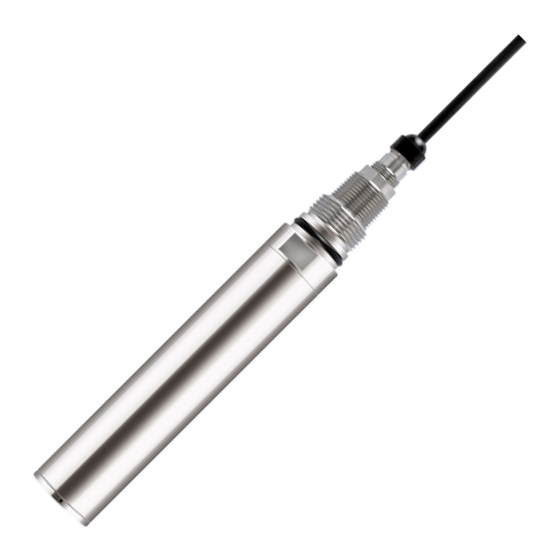
Sensor for turbidity and solids content
Hide thumbs
Also See for Turbimax CUS51D:
- Operating instructions manual (48 pages) ,
- Technical information (17 pages) ,
- Operating instructions manual (32 pages)

Related Manuals for Endress+Hauser Turbimax CUS51D


Summary of Contents for Endress+Hauser Turbimax CUS51D
- Page 1 Products Solutions Services BA00461C/07/EN/15.13 71219749 Operating Instructions Turbimax CUS51D Sensor for turbidity and solids content...
- Page 2 Corrective action This symbol alerts you to situations that can result in NOTICE damage to property and equipment. Cause/situation Consequences if safety message is not heeded ‣ Action/note Symbols Additional information, tips Permitted or recommended Forbidden or not recommended Endress+Hauser...
-
Page 3: Table Of Contents
Turbimax CUS51D Table of contents Safety instructions ....4 Technical Data ....35 Requirements for the personnel . -
Page 4: Safety Instructions
Safety instructions Turbimax CUS51D Safety instructions Requirements for the personnel ‣ Installation, commissioning, operation and maintenance of the measuring system must only be carried out by trained technical personnel. ‣ The technical personnel must be authorized by the plant operator to carry out the specified activities. -
Page 5: Product Safety
Turbimax CUS51D Safety instructions Product safety The product is designed to meet state-of-the-art safety requirements, has been tested and left the factory in a condition in which it is safe to operate. Relevant regulations and European standards have been observed. -
Page 6: Incoming Acceptance And Product
Scope of delivery The scope of delivery comprises: • 1 sensor Turbimax CUS51D in the ordered version • 1 Operating Instructions BA00461C/07/EN If you have any questions, please contact your supplier or your local sales center. Certificates and approvals Declaration of conformity The product meets the requirements of the harmonized European standards. -
Page 7: Installation
Turbimax CUS51D Installation Installation Dimensions a0013179 Fig. 1: Dimensions See the "Accessories" section for the dimensions of the cleaning unit Endress+Hauser... -
Page 8: Installation Instructions
Turbimax CUS51D Installation instructions 3.2.1 Measuring system A complete measuring system comprises: • Turbidity sensor Turbimax CUS51D • Transmitter Liquiline • Assembly: – Assembly Flexdip CYA112 and holder system Flexdip CYH112 or – Retractable assembly , e.g. Cleanfit CUA451 a0012965 Fig. - Page 9 Installation a0013334 Fig. 3: Measuring system with immersion assembly (example) Transmitter Liquiline Assembly Flexdip CYA112 Weather protection roof Turbidity sensor Turbimax CUS51D Holder system Flexdip CYH112 a0012964 Fig. 4: Measuring system with retractable assembly (example) Turbidity sensor Turbimax CUS51D Transmitter Liquiline...
-
Page 10: Installation Examples
Fixed installation with wastewater assembly a0013383 a0012965 Fig. 5: Installation secured on railing Fig. 6: Installation with upright post Turbidity sensor Turbimax CUS51D Flexdip CYH112 holder Flexdip CYA112 wastewater assembly Multichannel transmitter Liquiline CM44x Flexdip CYH112 holder Weather protection cover Railing... - Page 11 Flexdip CYH112 holder Flexdip CYA112 wastewater assembly Railing Turbidity sensor Turbimax CUS51D The chain retainer is particularly suitable for applications that require a sufficient distance between the mounting location and the edge of the aeration basin. As the assembly is freely suspended, any vibration of the upright post is practically ruled out.
- Page 12 Turbimax CUS51D Cleaning unit a0013259 Fig. 9: Turbimax CUS51D sensor with cleaning unit The cleaning unit is particularly suitable for clear water and media containing fats/oils that tend to cause heavy buildup. Mount the cleaning unit as follows: Fit the cleaning unit onto the sensor as far as it will go.
- Page 13 Turbimax CUS51D Installation 3.3.2 Pipe installation Arrow 1 shows the flow direction. The installation angle must not exceed 90°. The recommended installation angle is 75°. The optical windows of the sensor have to be aligned parallel to the flow direction ( = 90°) or face the flow direction (...
-
Page 14: Post-Installation Check
Installation Turbimax CUS51D The following figure illustrates various installation positions in pipes and indicates whether they are permitted or not. a0013011 Fig. 14: Orientation and installation positions (with retractable assembly CUA451) • The pipeline diameter must be at least 100 mm (4") if reflective materials (e.g. stainless steel) are used. -
Page 15: Wiring
Turbimax CUS51D Wiring Wiring WARNING Device is energized Improper connection can cause injury or death. ‣ The electrical connection must only be carried out by a certified electrician. ‣ Technical personnel must have read and understood the instructions in this manual and must adhere to them. -
Page 16: Device Description
Device description Turbimax CUS51D Device description Sensor design The sensor is designed for the continuous in-situ measurement of turbidity and solids content. The sensor is designed as a 40 mm sensor that can be operated directly and completely in the process without the need for further sampling (in situ). - Page 17 Turbimax CUS51D Device description 135° 90° a0012986 Fig. 17: Principle operating mode of the turbidity sensor Light source 135° light receiver 90° light receiver If only a small number of particles is in the medium, most of the light will be scattered to the 90°...
- Page 18 Device description Turbimax CUS51D The turbidity sensor CUS51D is equipped with two independent sensor units that are arranged in parallel. The application-specific analysis of both signals results in stable measured values. a0012966 Fig. 19: Arrangement of the light souces and the light receivers Light sources 1 and 2 135°...
-
Page 19: Measuring Methods
Turbimax CUS51D Device description Measuring methods Four-beam pulsed light method The method is based on two light sources and four light receivers. Long-life LEDs are used as monochromatic light sources. To eliminate interference from extraneous light sources, these LEDs are pulsed. - Page 20 Device description Turbimax CUS51D 135° backscattered light method The transmitted light beam is scattered by the solid matter particles in the medium. The backscattered beams are detected by scattered light receivers, which are arranged next to the light sources. The turbidity of the medium is determined by the amount of backscattered light.
-
Page 21: Application
Turbimax CUS51D Device description Application The sensor enables measurement in a variety of ways that are adapted to suit the specific measurement problems. The method is set by the choice of application and the reference model. Application type "Clear water"... - Page 22 Device description Turbimax CUS51D Application areas Model name Application Unit Compensation Formazine Process water, sewage treatment plant outlet FTU / FNU Kaolin Filterable solids, process water, sewage treatment mg/l ; g/l; plant outlet, activated sludge in low concentration ppm; % , mineralic solids (sands) g/l;...
-
Page 23: Calibration
Turbimax CUS51D Device description Calibration The sensor is precalibrated on leaving the factory. As such, it can be used in a wide range of applications (e.g. clear water measurement) without the need for additional calibration. The factory calibrations are based on "three-point calibration". The kaolin and formazine applications are already fully calibrated and can be used without further calibration. - Page 24 Device description Turbimax CUS51D Process water application Inlet Process control Filter rinsing Sedimentation tank Process water Process sludges 5.5.2 Choosing the type of calibration 1 to 5 points can be calibrated for all applications. The following recommendation describes the common types of calibration.
- Page 25 Turbimax CUS51D Device description Effects of the various types of calibration Factory calibration Factory calibration New calibration curve New calibration curve Calibration point Calibration point Suspended solids (g/l) Suspended solids (g/l) a0020210-en a0020211-en Fig. 23: Single-point calibration Fig. 24: Two-point calibration...
- Page 26 Device description Turbimax CUS51D 5.5.3 Single-point calibration With single-point calibration, the sensor can remain immersed in the process medium. Proceed as follows: Remove a sample of the medium in close proximity to the sensor for the laboratory measurement. Send the sample to the laboratory to measure the turbidity or solids content.
- Page 27 Turbimax CUS51D Device description Preparing the CUS51D sensor for calibration: Clean the optical components (windows) of the sensor with water and a brush. Put the sensor into the calibration vessel. When doing this, observe the following instructions. • Do not immerse the sensor vertically into the sample. Immerse the sensor at an angle. By doing this, you will prevent air bubbles building up around the windows.
- Page 28 Device description Turbimax CUS51D During calibration, note the following points: • The calibration points should cover the complete measuring range. • Be extremely careful when determining the laboratory measured value (the quality of the laboratory measurement has a direct impact on the accuracy of the sensor).
-
Page 29: Stability Criterion
Turbimax CUS51D Device description Stability criterion During the calibration process, the measured values returned by the sensor are checked to ensure they remain constant. The stability criterion defines the maximum amount the measured values may deviate during calibration and still be accepted. -
Page 30: Diagnostics And Troubleshooting
Diagnostics and troubleshooting Turbimax CUS51D Diagnostics and troubleshooting Troubleshooting must take account of the whole measuring system: • Transmitter • Electrical leads and connectors • Assembly • Sensor The possible causes of failure listed in the following table primarily refer to the sensor. -
Page 31: Maintenance
Turbimax CUS51D Maintenance Maintenance You have to perform maintenance tasks at regular intervals. We recommend setting the maintenance times in advance in an operations journal or log. The maintenance cycle primarily depends on the system, the installation conditions and the medium in which measurement takes place. -
Page 32: Repair
The device must be returned if repairs or a factory calibration are required, or if the wrong device has been ordered or delivered. According to legal regulations, Endress+Hauser, as an ISO-certified company, is required to follow certain procedures when handling returned products that are in contact with medium. -
Page 33: Accessories
Turbimax CUS51D Accessories Accessories Assemblies Wastewater assembly Flexdip CYA112 • Modular assembly system for sensors in open basins, channels and tanks • Versions in stainless steel or PVC • Ordering per product structure (--> Online configurator: www.products.endress.com/ cya112) • Technical Information TI00432C/07/EN Retractable assembly Cleanfit CUA451 •... -
Page 34: Compressed Air Cleaning
Accessories Turbimax CUS51D Compressed air cleaning Cleaning system with pressurized air • Connection: 6 or 8 mm (metric) or 6.35 mm (¼") • Materials: POM/V4A • 6/8 mm order number: 71110782 • 6.35 mm (¼") order number: 71110783 72 (2.83) -
Page 35: Technical Data
Turbimax CUS51D Technical Data Technical Data 10.1 Input Measured variable Turbidity Solids content Temperature Measuring range CUS51D-**C1 Application Turbidity 0 to 4000 FNU Formazine display range up to 9999 FNU Solids content 0 to 4 g/l Kaolin, filterable solids Temperature -20 to +80 °C (-4 to +176 °F) -
Page 36: Performance Characteristics
Technical Data Turbimax CUS51D 10.2 Performance characteristics Maximum measured error Turbidity < 2% of the measured value or 0.1 FNU (the respectively larger value is valid) Solids < 5 % of the measured value or 1 % of full scale ( the respectively larger value is valid);... -
Page 37: Environment
Turbimax CUS51D Technical Data a0020169-en For solids the achievable measuring ranges are depending of the actual medium and can deviate from the recommended operating ranges. Factory calibration FNU, FTU and solids concentration according to the application table Standard: 3 points Drift Thanks to electronic control the sensor works drift compensated in a wide range. -
Page 38: Mechanical Construction
Technical Data Turbimax CUS51D 10.5 Mechanical construction Dimensions See "Installation conditions" Weight approx. 0.7 kg (1.5 lbs) without cable Materials Sensor Stainless steel 1.4404 (AISI 316 L) or Stainless steel 1.4571 (AISI 316 L) Optical windows Sapphire O-rings EPDM Process connections G1 and NPT ¾' '... -
Page 39: Index
Turbimax CUS51D Index Accessories ........33 Nameplate . - Page 40 71219749 www.addresses.endress.com...
- Page 41 Endress+Hauser Configurator 2016 SC United States v2 2350 Endress Place Greenwood, IN 46143 Turbimax CUS51D Turbidity Sensor, optical. Application: Water, waste water CUS51D-AAD1A7+IB Digital sensor, Memosens protocol Sensor head: G1, NPT3/4 71094594 Automatic sensorcheck Factory calibration SPK: CDA Basic model...
Need help?
Do you have a question about the Turbimax CUS51D and is the answer not in the manual?
Questions and answers