Table of Contents
Advertisement
Quick Links
Advertisement
Table of Contents

Subscribe to Our Youtube Channel
Related Manuals for Aerpro FP9750


Summary of Contents for Aerpro FP9750
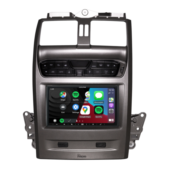
- Page 1 FP9750 INSTALL KIT BA- BF FALCON TO SUIT & TERRITORY SX-SY...
- Page 2 Product and Install Information If you would like to find more information on this product or download an up to date digital copy of this manual, please visit the https://aerpro.com website and search for your model or scan the QR code below.
- Page 3 Inclusions 1 x Double DIN facia kit 1 x Built-in HVAC and steering wheel control unit 1 x Main wiring harness 1 x Universal SWC patch lead 1 x Video in/out lead 1 x Mounting kit 4 x M6 Bolts 1 x User/Install manual...
-
Page 5: Interface Functions
Interface Functions NOTE: The Climate control buttons will not work without ignition power, including Door Lock & In-Cabin Light Front Demister Fresh air is blown through the heater core and then ducted to and distributed over the interior surface of the vehicles windshield Rear Demister The demister clears condensation from the rear back glass... - Page 6 Interface Functions Air Circulation Mode Changes between fresh air drawn in directly from the outside of the vehicle, or recirculation where the air is drawn from inside the cabin...
- Page 7 Interface Functions Mode Changes the vent positions for heating and cooling...
- Page 8 Interface Functions Heating & Cooling Temperature Press up to increase temperature, press down to decrease temperature. Left hand side buttons adjust passenger side (Front & Rear). Right hand side buttons adjust drivers side (Front & Rear) temperature settings...
- Page 9 Interface Functions Air conditioning On or Off Press to turn the air conditioning On/Off or vice versa. This can be changed and reversed in the setup menu. NOTE: Holding down the A/C button completely turns the A/C heating and cooling system off on Dual Zone models Fan Speed Adjustment Pressing these will turn the fan speed up and down.
- Page 10 Interface Functions Trip Computer This displays information relating to Average speed, Average fuel use, Trip time and remaining fuel in kilometres. Press and hold the trip computer button to reset the average speed on dual zone models. Beep sound will confirm reset. NOTE: Trip button only works when not in the climate control display or settings menu Auto Function...
- Page 11 Interface Functions Auto Function (Semi Auto) Press to manually control the climate control to a desired temperature. NOTE: This will only work on Dual Zone models Press again to turn the climate control off...
- Page 12 Interface Functions NOTE: The Climate control buttons will not work without ignition power, including Door Lock & In-Cabin Light Auto Door Lock Press to lock and unlock all doors in the vehicle Traction Control Press to turn vehicles traction control on or off NOTE: Only works on supported models prior to upgrade Interior Light Press to turn the vehicles factory interior light on or off...
-
Page 13: Menu Functions
Menu Functions Configuration Menu Press and hold the menu button for a few seconds to display the Configuration Menu. Press menu button to enter into sub menus and again to change settings. Press the Fan UP/DOWN buttons to navigate up and down between sub menus... - Page 14 Menu Functions Select Infoadapter settings/preferences to access (4 menus) Retained Accessory Power Controls what the headunit does after the vehicle is turned off. When Off is selected the headunit will turn off when the key is taken out of the ignition. When ON is selected the headunit will turn off when the key is taken out of the ignition and the drivers door is opened Climate Screen Timeout...
- Page 15 Menu Functions Installer Menu When in the configuration menu, press and hold the fan UP/DOWN buttons at the same time to access the installer menu Air Conditioner Type Choose between a single or dual climate system. NOTE: Dual climate systems can run as a single zone system.
- Page 16 Menu Functions Screen Size/ Position Allows the user to change the Infoadapter screen to fit to your headunits display Camera Connected Turns the reverse camera function On or Off if a reverse camera is fitted Invert AC Button This inverts the AC toggle. If you can still feel cold air coming out of your vents when AC is off, change this option Diagnostics Information on system...
-
Page 17: Installation
INSTALLATION AFTER BEFORE... -
Page 18: Tools Needed
Tools Needed Use the following tools to make dismantling the car and the installation of the new facia easier. NOTE: Do not use power tools, only use the tools recommended below and do not over tighten screws as they may damage the facia kit. 1. - Page 19 Centre Console Disassembly Removing gear shift trim (Auto) Shift the gear stick down to the “D” drive position Lift the front of the panel then pull the panel up to completely remove...
-
Page 20: Side Panel Disassembly
Side Panel Disassembly Removing side trim Undo the screw then lift up from the bottom and pull down from the top to remove the left side panel Repeat to remove the right side panel... - Page 21 Pocket Disassembly Removing tissue box and power socket Remove the 2 screws holding the tissue box in place Pull out the tissue box, disconnect the power harness from the socket and put the tissue box aside...
-
Page 22: Top Panel Disassembly
Top Panel Disassembly Removing top panel trim Remove the top panel by CAREFULLY prying the edges away from the dash. NOTE: Age and sun damage can make this panel brittle and can break easily Remove the top panel and put it aside. Remove the screw at the top holding the factory unit in place and put aside... - Page 23 Headunit Removal Removing factory headunit face plate Remove the 2 x 8 mm bolts from the left side of the factory unit Remove the 2 x 8 mm bolts from the right side of the factory unit...
- Page 24 Headunit Removal Pull the unit away from the dash until it is loose (pic1) and unplug the 4 connectors and the antenna connector from beneath the factory unit (pic2-3). Remove the factory unit and place it on a bench (pic2) (pic1) (pic3)
- Page 25 Headunit Disassembly Remove the 4 x screws from both the left and right factory brackets...
- Page 26 Headunit Disassembly Remove the green plug and unscrew the earth strap Remove the factory unit from the plastic 2-10...
-
Page 27: Module Disassembly
Module Disassembly Removing The FOB Transceiver Module Remove the 2 screws from the transceiver, remove and put it aside 2-11... - Page 28 Vent Disassembly Removing The Vent From Factory Facia Remove the 3 screws holding the vent in place, remove it and put it aside 2-12...
-
Page 29: Mounting Clips
Mounting Clips The new facia comes with pre installed mounting clips. The factory facia mounting clips can also be retained and reused if needed. Control Module Removal Remove 4 screws from Body Control Module (coloured plastic module). Discard and use supplied 4 x M6 bolts when remounting 2-13... -
Page 30: Dip Switch Settings
Changing The Dip Switch DIP switches can be changed to match the headunit and rear camera being used with this installation kit. Make these changes before installing the kit. Check the rear camera and steering wheel control requirements for your devices. Step1. -
Page 31: Vent Assembly
Vent Assembly Re-attaching Factory Vent To New Facia Place the new plastics on a soft surface and turn it over so it is lying face down Line up the vent to the new plastics and attach it using the 3 screws taken out earlier. NOTE: Please use a screwdriver (not a power tool) to hand tighten the screws. - Page 32 Vent Assembly Re-attaching FOB Transceiver Module Mount the module back onto the vents Re-attaching Body Control Module Mount the Colour Body Control Module to the metal bracket on new plastics using the 4 M6 bolts provided and connect the lead from the FOB Transceiver Module 2-16...
- Page 33 Body Control Module Mounting Note: Before going further, it is a good idea to check that the Colour Body Control Module retaining bracket is fitted correctly. If the mounting bracket is the wrong way around, and mounted incorrectly the BCM will hit the back of the heater box and the plugs will not reach.
- Page 34 Mounting Aftermarket Headunit Mount the aftermarket head-unit to the mounting brackets. Leave the screws a little bit loose to allow adjustment of the screen to the desired depth. Tighten the screws 2-18...
- Page 35 Connecting USB Pass Through & Reverse Camera Connect the USB/USB’s if present. Connect the reverse camera input to the video lead and then connect it to the module. 2-19...
- Page 36 Connecting Steering Wheel Controls Connect an Aerpro APP series (brand specific) secondary harness (sold separately) and a patch lead to the aftermarket unit. Connect to ISO plugs in main harness and connect to module NOTE: It is important to connect brand specific or correctly modified...
-
Page 37: Connecting Antenna
Connecting Antenna Connect any other cables like the park brake, reverse and speed pulse if applicable. Tape up any unused cables. If you find the factory antenna lead is not long enough to connect to the back of the new headunit, you may need to purchase an aerial extender like the APP332 model (sold separately). - Page 38 OEM Reverse Sensor (Vehicle Option) Retaining the OEM reverse sensor alerts Attach the reverse sensor connector to the Aerpro AP1WAMP amplifier module (sold separately) Place the audio amplifier behind the headunit 2-22...
- Page 39 OEM Reverse Sensor (Vehicle Option) Attaching the extension speaker Connect the 3.5mm extension jack of the Aerpro CBXS extension speaker (sold separately) to the amplifier module input Securely mount the extension speaker in an appropriate position. You can adjust the volume of the amplifier module by turning the adjustment dial.
-
Page 40: Main Harness Installation
Main Harness Installation Plug the main harness into the vehicle. Due to the limited depth we recommend using a mechless head unit (No CD/DVD player) for this kit as some head units are too deep to fit within the space available. 2-24... - Page 41 Facia Kit Installation Place into position taking care to keep all cables out of the way. Make sure the antenna cable is placed into the back of the headunit 2-25...
- Page 42 Facia Kit Installation Facia Kit Installation Re-attach the four connectors to the body control module. Switch the vehicles parking lights on to test illumination of the HVAC buttons. Turn on the vehicles accessories to test the steering wheel controls and audio 2-26...
- Page 43 Facia Kit Installation Facia Kit Installation Once all of the functions have been tested, screw in the top section and bolt in the bottom section using the one screw and the 4 bolts retained earlier Replace the tissue pocket, reconnect the power socket, replace the top trim (CAREFULLY), replace the left and right side panels and screw back in.
-
Page 44: Installer Notes
Installer Notes 2-28... -
Page 45: Technical Assistance
Technical assistance If you need assistance setting up or using your Aerpro product now or in the future, call Aerpro Support. Australia TEL: 03 – 8587 8888 FAX: 03 – 8587 8866 Mon-Fri 9am – 5pm AEST Please retain this user guide for future reference. -
Page 46: Wiring Diagram
Wiring diagram Aftermarket unit Not included (Sold separately) Camera in Remote in Secondary Harness Aftermarket camera Main Harness Park brake (Green) Vehicle Harness Not Used(Grey) Amp Remote Input (Blue/White) Reverse (Purple) Speed Pulse(Pink) Factory Sub input (if Applicable) AP1AMP Reverse tone amplifier CBXS speaker 2-30... - Page 47 SWC Patch Harness Configuration Use Key 1 Bullet Use 3.5mm Jack for terminal for these these Head-units Head-units Philips, ALPINE Nakamichi Cut Green Link Cut Orange & Purple Wire Kenwood CLARION Cut Orange & Cut Purple Link Green Wire PIONEER No cutting Cut Green &...
- Page 48 SWC Patch Harness Configuration Kenwood/JVC : Some Kenwood and JVC radios have 2 steering control inputs. A 3.5mm socket (Remote IN) and Blue with Yellow trace wire. To send direct translated codes to your Kenwood/JVC radio, configure the patch lead up as Kenwood or JVC outlined in the configuration assignments and connect the Brown patch lead wire (KEY 1) used.
Need help?
Do you have a question about the FP9750 and is the answer not in the manual?
Questions and answers