Advertisement
Advertisement
Table of Contents

Subscribe to Our Youtube Channel
Related Manuals for Aerpro FP9680


Summary of Contents for Aerpro FP9680
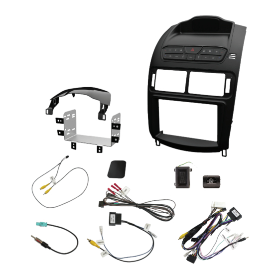
- Page 1 INSTALLATION MANUAL Model FP9680 FALCON TO SUIT 21-03-24...
-
Page 2: Tools Needed
Tools Needed Use the following tools to make dismantling the car and the installation of the new facia easier 1. Panel Remover 2. Phillips Head Screwdriver 3. Socket - 7 & 8 mm 4. Side Cutters 6. Cable Ties 5. Small Pick 7. - Page 3 Centre Console Disassembly Removing pocket (Auto) Eject any compact disks still in the factory unit. Shift the gear stick down to the “D” drive position. Firmly pull the storage compartment outwards towards you. Take the pocket out and put it aside.
- Page 4 OEM Headunit Removal Removing retaining bolts Using a 7mm socket driver or ratchet, remove the 2 short bolts at the back and an 8mm socket for the two long bolts on the sides to loosen the factory unit at the bottom.
- Page 5 OEM Headunit Removal Removing top panel trim Using a flat pry tool, carefully leaver the top panel up at the side and remove. Removing facia Remove the two 7mm bolts at the top and unplug the OEM monitor connectors.
- Page 6 OEM Headunit Removal Holding the factory unit at the top and bottom, pull the unit back towards you to remove.
- Page 7 OEM Headunit Disassembly Removing factory headunit face plate Place the unit on a soft surface to remove the screws holding the left & right side brackets on.
- Page 8 OEM Headunit Removal Undo the 3 screws holding the factory vent in place. Put aside screws to be reused.
- Page 9 OEM Headunit Disassembly Remove the cable from the retaining clip on the side of the vent. Remove the vent and put aside.
-
Page 10: Dip Switch Settings
Changing The Dip Switch DIP switches can be changed to match the headunit and rear camera being used with this installation kit. Make these changes before installing the kit. Check the rear camera and steering wheel control requirements for your devices. Step1. -
Page 11: Vent Assembly
Vent Assembly Reattaching the vents Place the new kit, face down on a soft surface. Place the factory vent into position and secure using the 3 screws retained earlier. - Page 12 Headunit Assembly Installing your headunit Place the headunit into the mounting bracket and loosely attach with screws on either side. Adjust the headunit to the desired depth before tightening the mounting screws on both sides.
- Page 13 Headunit Assembly Connect the main harness to the control unit. The wires can be routed up through the cable management clip on the vent. Connect the 4 pin video plug, and connect the yellow RCA plug to the reversing camera input on the aftermarket head unit. Connect the purple reverse output wire to headunit reverse trigger.
- Page 14 Plug the other end of the SWC patch lead into the aftermarket headunit’s steering wheel remote input. Connect the brand specific secondary harness (Aerpro App8 series sold separately) into the aftermarket headunit. NOTE: It is important to connect brand specific or correctly modified universal patch lead to module before powering up.
- Page 15 Headunit Assembly Connect the ISO connectors from the main harness to the secondary harness. Connect any other cables like park brake, reverse and speed pulse if available. Tape up any unused cables. Tape up the now obsolete plug at the top so it does not rattle around and fit the new top panel (supplied) into place.
- Page 16 Headunit Assembly Connect the subwoofer retention harness to the vehicle connector. Connect the blue/white wire to the amplifier remote from the the main harness. Connect the black wire to the ground wire from the main harness. (See page 17 diagram). Note: Only for vehicles with factory subwoofer.
- Page 17 Headunit Assembly Plug the main harnesses and antenna adapter into the vehicle. Place the entire unit into the vehicle resting at the top, making sure all of the cables are out of the way. Gently push the unit into place. Switch the vehicle to accessories and test all functions such as steering wheel controls,audio, illumination of the HVAC buttons and the climate controls.
-
Page 18: Wiring Diagram
Wiring diagram Aftermarket unit Not included (Sold separately) Camera in Steering Remote in Secondary Harness Vehicle Main Harnesses Harness Park brake (Green) Dip switch access Ground Remote Mute (Grey) (Black) (Blue) Patch Reverse (Purple) cable to change Speed Pulse(Pink) gender Chime retention module Factory Subwoofer and speaker box... - Page 19 SWC Patch Harness Configuration Use Key 1 Bullet Use 3.5mm Jack for terminal for these these Head-units Head-units Philips, ALPINE Nakamichi Cut Green Link Cut Orange & Purple Wire Kenwood CLARION Cut Orange & Cut Purple Link Green Wire PIONEER No cutting Cut Green &...
- Page 20 SWC Patch Harness Configuration Kenwood/JVC : Some Kenwood and JVC radios have 2 steering control inputs. A 3.5mm socket (Remote IN) and Blue with Yellow trace wire. To send direct translated codes to your Kenwood/JVC radio, configure the patch lead up as Kenwood or JVC outlined in the configuration assignments and connect the Brown patch lead wire (KEY 1) used.
-
Page 21: Technical Assistance
Technical assistance If you need assistance setting up or using your Aerpro product now or in the future, call Aerpro Support. Australia TEL: 03 – 8587 8888 FAX: 03 – 8587 8866 Mon-Fri 9am – 5pm AEST Please retain this user guide for future reference. -
Page 22: Installer Notes
Installer Notes...
Need help?
Do you have a question about the FP9680 and is the answer not in the manual?
Questions and answers