Table of Contents
Advertisement
Quick Links
Advertisement
Table of Contents

Subscribe to Our Youtube Channel
Related Manuals for Aerpro VE 2 Series


Summary of Contents for Aerpro VE 2 Series
- Page 1 SERIES 2 INSTALL KIT FP9550GK & FP9550BK INSTALLATION/USER MANUAL...
-
Page 2: Installation Information
Product and Install Information If you would like to find more information on this product or download an up to date digital copy of this manual, please visit the aerpro.com website and search for your model or scan the QR code below. -
Page 3: Tools Needed
Tools needed Use the following tools to make dismantling the car and the installation of the new facia easier. NOTE: Do not use power tools, only use the tools recommended below and do not over tighten screws as they may damage the facia kit. Also take care in removing the vehicles trim as over time they may have become brittle. -
Page 4: Product Overview
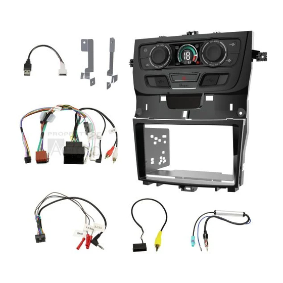
Product overview The Aerpro FP9550GK/BK VE Series 2 Facia Installation Kit is Australian designed and engineered and has been made for fitting a double DIN aftermarket radio, CD or DVD player to the original double DIN enclosure. The trims between these two models varies as shown below and are model specific. - Page 5 Inclusions 1x Double DIN facia kit 1x Gunmetal trim panel (FP9550GK) or 1x Piano Black trim panel (FP9550BK) 1x Built-in HVAC and SWC unit 1x Universal SWC patch lead 1x Factory USB retention lead 1x Camera retention lead 1x Antenna adapter 1x Mounting kit 2x Support brackets 1x User/Install manual...
- Page 6 Dash Disassembly Reset factory HVAC system It is recommended that you re-calibrated the factory HVAC heater valves or ducting positions before removal of the factory head unit. Press and hold the rear demister for 5 seconds until you hear the actuators re-calibrate. NOTE: Remove any Cd’s in the from the factory head unit before uninstalling Remove right side dash panel Insert a panel remover and lever outwards...
- Page 7 Dash Disassembly Remove right side trim Insert a panel remover and lever outwards Remove right side trim Continue to the left side with the panel remover FP9550GK FP9550BK Page 7...
- Page 8 Dash Disassembly Remove left side panel Insert a panel remover and lever outwards Remove left side dash trim Insert a panel remover and lever towards yourself working your way to the centre of the dash FP9550GK Page 8...
- Page 9 Dash Disassembly Remove glovebox There are 2 x screws to remove from the bottom of the glove box Remove glovebox Unclip the panel underneath the glovebox to access glove box light and mounting screws Page 9...
- Page 10 Dash Disassembly Remove glovebox Twist to remove the glove box light from the panel (Model dependent) and place trim aside until reassembly Remove glovebox There are 2 x screws to remove at the bottom of the glovebox as indicated Page 10...
- Page 11 Dash Disassembly Remove glovebox There are 5 x screws to remove from around the top of the glove box. Remove the outer screw covers with the small flat head screwdriver or pick CAUTION Glovebox may drop when screws are removed Remove glovebox Once the glovebox is unscrewed, disconnect the connector at the rear to completely remove the glovebox from the vehicle.
- Page 12 Dash Disassembly Remove left side center console panels The panels are held in with 1 plug and 2 inner clips. Release centre of plug and remove. Pull the lower panel downwards and out. Then pull the top panel outwards and downwards to release from the clips. Remove left side center console trim Once removed, place the panels aside for reassembly Inner clips...
- Page 13 Dash Disassembly Disconnect Antenna Disconnect all antenna and USB connectors. Press down on the top of the connector to remove from the head unit Remove under steering wheel cover Insert a panel remover and lever towards you to remove the trim, repeat this process on the opposite side.
- Page 14 Dash Disassembly Remove under steering wheel cover While unclipping, be sure to hold up the panel and not let it drop to protect the headlight switch connection Remove right side center console panels The panels are held in with 1 plug and 2 inner clips. Release centre of plug and remove.
- Page 15 Dash Disassembly Remove rear camera plug & quadlock Unclip the rear camera connector below the quadlock To remove the quadlock connector, press the sides marked with arrows inwards. The lever will release then pull outwards to detach from the head unit. Press the sides marked with arrows inwards Connector released Page 15...
- Page 16 Dash Disassembly Remove centre panel trim (Calais speaker shown) Use pick tool or flat headed screwdriver to lift panel or grille. Put aside for reassembly Remove centre panel trim top screws Unscrew the 2 screws holding the main factory fascia in place Page 16...
- Page 17 Dash Disassembly Main factory facia removal Unscrew the left hand side screw holding the main factory fascia in place Main factory facia removal Unscrew the right hand side screw holding the main factory fascia in place Page 17...
- Page 18 Dash Disassembly Remove centre console trim Apply the handbrake and place the gear shift in the neutral position. Using a panel remover, lift the trim around the gear stick holding the window controls. Then carefully lift the top by hand to release the retaining clips Remove centre console trim Unplug the 3 connectors attached to the centre console trim Page 18...
- Page 19 Dash Disassembly Remove pocket if applicable Unscrew left and right hand side screws and remove Remove pocket if applicable Pull upwards and towards you to remove Page 19...
- Page 20 Dash Disassembly Remove tray if applicable Unscrew left and right hand side screws and remove Remove tray if applicable Pull upwards and towards you to remove Page 20...
- Page 21 Dash Disassembly Remove centre console side panel Unscrew left and right hand side screws and remove Remove centre console side panel Carefully lift the base of the centre console panel up to loosen. Pry the centre top retaining clip with the removal tool then pull the top gently towards you to release all remaining retaining clips Page 21...
- Page 22 Dash Disassembly Remove factory screen and dash panel Hold at the top and base and pull gently forward to remove FP9550GK FP9550BK Remove factory head unit Unscrew the 4 main screws Page 22...
- Page 23 Dash Disassembly Remove factory head unit and cage Pull the head unit forward and out to remove to expose the head unit holding cage. The cage is not required in the install. The cage can be removed without removing all of the centre console by cutting away part of the radio support.
- Page 24 Dash Disassembly Remove factory head unit cage Remove the 6 screws on the top left and right sides of the cage trim Remove factory head unit cage To remove the cage and for clearance of the new facia, part of the radio support needs to be cut on each side and removed Page 24...
- Page 25 Dash Disassembly Remove factory head unit cage Once the radio support is cut and removed, the cage will then be able to be removed and is no longer required, retain these screws for later use. Re-screw factory side trims Re-screw the trims back in place Page 25...
- Page 26 Adding ancillary support brackets Ancillary support bracket positioning The brackets are designed for re-attaching the side panels to the mounting points that were lost when the cage was removed. Refer page 12 & 37. The brackets attach to the existing mounting locations. Ancillary support bracket on drivers side Attach the support bracket using a screw from the cage removal process Page 26...
- Page 27 Adding ancillary support brackets Ancillary support bracket on passenger side Attach the support bracket using a screw from the cage removal process Finished result For the correct position of the support brackets see the image below Page 27...
- Page 28 Factory head unit disassembly Removing factory vents (FP9550GK) Place the factory head unit on face down on a soft surface. Remove the factory vents by removing 4 screws underneath and 1 screw on top of the vent. This step not required for FP9550BK model. Removing factory face panel Remove the 3 screws holding the face panel in place Page 28...
- Page 29 Facia Kit assembly Installing and aligning your head unit Place the head unit into the mounting bracket and loosely attach with screws on either side. Adjust the head unit to the desired depth before tightening the mounting screws on both sides. Attaching facia to factory top panel When joining the 2 pieces together make sure the tabs on both align correctly before screwing into place...
- Page 30 Facia Kit assembly Aligning the tabs The two tabs slot into the space provided assuring correct alignment Page 30...
- Page 31 Facia Kit assembly Attaching facia to factory top panel Replace the 3 screws back into position on the top and two sides Page 31...
- Page 32 Facia Kit assembly Re-attaching factory vents Replace the 5 screws back into position on the top and bottom of the vents This step not required for FP9550BK model. Connecting to head unit Depending on the brand of head unit connect the 3.5 mm connector or single wire of the patch lead.
- Page 33 Connecting to head unit Attach the reverse camera lead to the head unit (if applicable). Attach the antenna adapter to the head unit and vehicle. Attach the reverse, park brake and VSS cables (if available). Attach the factory USB retention cable located on the passenger side. The factory microphone can also be used with a 3.5mm jack or 2.5mm adaptor (if applicable for your head unit/not supplied).
-
Page 34: Main Harness Installation
Main Harness Installation Connect an Aerpro APP series (brand specific) secondary harness (sold separately) and a patch lead to the aftermarket unit. Connect to ISO plugs in main harness and connect to module. NOTE: It is important to connect brand specific or correctly modified universal patch lead to module before powering up... - Page 35 Main Harness Installation Connecting to vehicle quadlock Connect the main harness into the vehicles quadlock last, once all other connections are complete. This allows the system to correctly configure the HVAC & SWC. Loosely place the completed facia into the dash to test functionality. Testing the head unit &...
- Page 36 Facia Kit assembly Once all of the functions have been tested, screw in the top section using the 2 screws retained earlier. FP9550GK FP9550BK Page 36...
- Page 37 Facia Kit assembly Screw in the bottom section using the 2 screws retained earlier. Attach the ancillary support brackets to the headunit bracket using the 2 of the screws retained earlier from the removal of the cage. Reassemble in the reverse order to the disassembly to finish the installation Page 37...
-
Page 38: Product Structure
Product structure 1.Front/Rear demister air button 6.Recirculated air on/off button 2.Left rotary dial button (Rotate,Tap,Hold) 7.USB charging and sync port 3.LCD display information screen 8.USB charging and sync port 4.Right rotary dial button (Rotate,Tap,Hold) 9.Fan speed DOWN 5.Fan speed UP Screen display Rear demister Front demister... - Page 39 Functions Turning air-conditioning ON/OFF Once powered up, press and hold the right rotary dial button for 3 seconds until you hear a click sound. Once you release your finger the air-conditioner icon (Snowflake) illuminates. Press and hold again to turn off. When turning on the air-conditioner the system will remember your previous user settings.
- Page 40 Positioning To select different air positions in the vehicle tap the RIGHT rotary button. Positions are for the Head/Feet, Chest, Chest/Feet and Feet (See icons below). Selecting Head/ Feet will automatically turn on the AC. Page 40...
- Page 41 Functions Recirculation/Air Passthrough button Tap this button to cycle between Recirculation and Air Passthrough. The corresponding icon will illuminate. Page 41...
- Page 42 Functions Front/Rear demister button When air-conditioner is turned on tap this button to active Rear Demister or hold this button to activate the Front Demister. HOLD Hold Re-Calibrating your HVAC System In the case that you may need to re-calibrate your heater valves or ducting positions.
- Page 43 Functions Fan speed To adjust the fan speed tap on either of the two right buttons. Top to increase fan speed and Bottom to lower fan speed. NOTE: When the fan is set at ‘Zero’, the cars air circulation will change to pass through.
- Page 44 Functions Automatic climate control To activate auto climate mode, tap the left hand rotary dial and then set the target temperature by rotating the right hand rotary dial to the desired level. The fans speed, the vent temperature and the air flow direction is fully automatic and will adjust itself based on what it needs to get to the required level.
- Page 45 Functions Automatic climate control continued When in Auto mode (SZ or DZ), the system is equipped with 3 levels of fan speeds. Fan LOW, Fan MID and Fan HIGH. Fan LOW Fan MID Fan HIGH To adjust the levels use Fan Up and Fan Down NOTE: If you change the vents while in Auto Climate, the vents will change, however the fan will remain on AUTO (AUTO Symbol will turn off).
- Page 46 Functions Single Zone Holding the LEFT rotary dial will activate Single Zone. The Dual Zone temperature display will change to a Single Zone temperature display. Hold Adjusting Temperature In Single Zone Mode the right rotary dial adjusts the temperature. Adjusting the left rotary dial will revert the system back to Dual Zone.
- Page 47 Functions Dual Sync When the Dual Zone is activated, the Driver and Passenger temps will be in sync. While they are in sync, both temps can be adjusted by the drivers dial. Rotate Dual Sync When the LEFT rotary dial is rotated, the passenger temp will be adjusted. Once this is done, Dual Sync will turn off and both temps can be adjusted independently.
- Page 48 Functions Anti-Pollution Mode Anti-Pollution mode will automatically switch between Passthrough and Re-Circulation based on the vehicles speed. This is to avoid the vehicle drawing in unwanted fumes when travelling at low speeds. Hold Activating Anti-Pollution Mode To activate Anti-Pollution Mode, hold the passthrough button for 5 seconds then release.
- Page 49 Functions Steering Wheel Control of the HVAC Tap the left hand scroll wheel to control your HVAC via the left and right scroll wheels on your steering wheel. AUDIO TRIP AUDIO TRIP Single Zone When in Single Zone the Left scroll wheel controls the fan speed and the Right scroll wheel controls temperature.
- Page 50 Functions Left scroll wheel Use the left scroll wheel to go up and down through audio tracks and radio stations. Audio button Press to select audio source. Trip button Press to access centre cluster settings. AUDIO Phone button • Single press to answer a call TRIP •...
- Page 51 Functions Parking Sensors Parking sensors are retained if your vehicle had them fitted from factory. The screen will automatically display the parking sensors when the vehicle is in Reverse or if the vehicle is travelling less that 15km/h. Front Sensors (When in Drive) The Front sensors are displayed at the top of the screen.
-
Page 52: Resetting The System
Resetting the system In the case of the system locking up or not functioning correctly, the unit can be reset to factory settings. Press & hold both left & right rotary knobs at the same time. Page 52... -
Page 53: Installer Notes
Installer Notes Page 53... -
Page 54: Wiring Diagram
Wiring diagram Reverse Camera Aftermarket Unit Vehicle Retention Harness Camera in Harness Antenna in Remote in Secondary Harness Vehicle Harness Main Harness Antenna booster Power (Blue) Park Brake (Green) Vehicle Harness Reverse (Purple) Speed Pulse(Pink) Factory Passive Microphone & AUX (To aftermarket unit if applicable) 3.5mm Jack 3.5-2.5mm Adapter... - Page 55 Pioneer/Sony config but if this is not working then changing to this new config should allow the phone button to work. PLEASE NOTE: Remove power from the Aerpro kit (unplug main quadlock plug) before changing patch lead configurations. This will allow the kit to reset its programming.
-
Page 56: Technical Assistance
Technical assistance If you need assistance setting up or using your Aerpro product now or in the future, call Aerpro Support. Australia TEL: 03 – 8587 8888 FAX: 03 – 8587 8866 Mon-Fri 9am – 5pm AEST Please retain this user guide for future reference.
Need help?
Do you have a question about the VE 2 Series and is the answer not in the manual?
Questions and answers