Advertisement
Quick Links
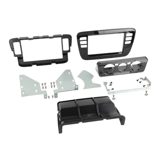
DoubleDIN Fitting Kit
* Only for models with manualair conditioning and glove box
pos. designation
(1) facia plate
(2) mountingbracket right
(3) mountingbracket left
(4) mounting frame
(5) facia climate control
(6) connection piece ahead
(7) template
(8) mountingbracket complete
(9) washer
(10) flat-head screw (M5x8)
(11) self-tapping screw with collar
10
1
Part Number.
FP8435
FP8436
10
3
11
4
Installation Manual
VW up! 2011-2016*
Colour
black
pianoblack
8
9
10
5
7
6
2
10
1
Advertisement

Subscribe to Our Youtube Channel
Related Manuals for Aerpro FP8435


Summary of Contents for Aerpro FP8435
- Page 1 DoubleDIN Fitting Kit Installation Manual VW up! 2011-2016* Part Number. Colour FP8435 black FP8436 pianoblack * Only for models with manualair conditioning and glove box pos. designation (1) facia plate (2) mountingbracket right (3) mountingbracket left (4) mounting frame (5) facia climate control...
- Page 2 OEM dashboardSEAT Mii/SKODA CITIGO /VW up!with manualair conditioning Pull off the circulatingairswitch...
- Page 3 Unclip panel Remove panel...
- Page 4 Remove 4 TX20 screws (screws willbe requiredfor reassembly) Place tworelease keys into the providedslots...
- Page 5 Partially removethe OEM head unit fromthe dashboard...
- Page 6 Disconnect the switch panel...
- Page 7 Disconnect the switch panel Fully removethe OEM head unit fromthe dashboard...
- Page 8 Disconnect all wiringfrom the OEM head unit Disconnect all wiringfrom the OEM head unit...
- Page 10 Pull 3 plugsand2 Bowden cables out ofthe air conditioningcontrol panel Pull the Bowdencable out of the airconditioningcontrol unit...
- Page 11 Pull the Bowdencable out of the airconditioningcontrol panel Release the attachment of the Bowden cable...
- Page 12 Openthe glove box...
- Page 13 Pull the centre console panel out fromthe dashboard...
- Page 14 Place the panelona flat surface Place the facia (5)of the airconditioning control unit centred onto the panel Drawan outline, usingthe facia (5) ofthe airconditioningcontrol unit as template Transferthe shape ofthe facia (5) of the airconditioningcontrol unit onto the panel...
- Page 15 Attention! Drawadditional lines with a 5mmgap inside the shape drawninthe previousstep Cut out the innerarea...
- Page 16 Cut out the innerarea...
- Page 17 See belowfor an imageof the removedsection Remove all roughedges with sandpaper...
- Page 18 Centre console panel after modification Remove the OEM airchannel If a doubleDIN head unit without CD/DVDdrive(mechless unit /maximal install depth 140 mm) is goingto be installed, the removalof the OEM airchannel is not neccessary: Please proceedto page20.
- Page 20 Cut out the markedareas Cut out the markedareas...
- Page 21 Cut out the front section of the markedarea ca- refully with a depth of app. 3 mm. ATTENTION!Please note the underlyingarea since it is needed forfixation ofthe mounting frame later. ATTENTION!This area MUST remain...
- Page 22 ca. 3 mm Viewof the dashboardafter cutting...
- Page 23 Fix the mountingframe (8). Markthe areas insidethe mountingframe Remove the mountingframe (8). Cut alongthe markedareas...
- Page 24 Drilla hole with a diameter of approx. 20 mm forthe relocation ofthe Bowden cables Fix the mountingframe (pos. 8) withthe aircondition control unit with 4 self-tappingscrews with collar (pos. 11)
- Page 25 Place the airconditioningcontrol unit into the dashboard Connect the Bowdencable to the aircondtioning control unit...
- Page 26 Reconnect the twoBowdencables to the airconditioningcontrol unit Reconnect the 3 OEMplugsto the airconditioningcontrol unit...
- Page 27 Attach the air conditioncontrol unitwith 2 self-tapping screws with collar (pos. 11) Push the panel aroundthe centre console.
- Page 28 Fix the facia (pos. 5) onthe bottom sidewiththe flat headed screw (pos. 10)and disk(pos. 9)
- Page 29 Install the circulating airswitch If a doubleDIN head unit without CD/DVDdrive(mechless unit /maximal install depth 140 mm) is goingto be installed, the next steps can be skipped: Please proceedto page35.
- Page 30 Separate top andbottom of the airchannel (see arrows) Bottom of the airchannel...
- Page 31 Markthe innersides, left andright, with the aidof the providedtemplate (pos. 7) Turnaroundand repeat the procedure on the other innerside...
- Page 32 Cut out the markedsections View of the air channel after after cutting...
- Page 33 New connection piece ahead of airchannel Press top andbottom part together usinga pincer(see arrows)untilthey snapin...
- Page 34 Install the air channel...
- Page 35 Place the mountingframe (pos. 4) overthe radioopeningand markthe position ofthe two drillholes (see arrows) Drilltwo holes app. Ø=3 mmat the markedlocations...
- Page 36 Mount both mountingbrackets (pos. 2 +3) and the mountingframe (pos. 4) to the doubleDIN head unit withthe flat-headedscrews (M5x8) (Pos. 10) ~ 30 mm We recommenda distance of approx.30 mmfromthe brackets to the front side of the unit...
- Page 37 Connect all requiredcircuit points according to the manualof the double DIN head unit. Push the doubleDIN head unit into the radioopening...
- Page 38 Connect the left switch panelwiththe designatedconnector Place the left switch panelintothe mountingframe...
- Page 39 Connect the rightswitch panelwiththe designated connector Place the rightswitch panel intothe mountingframe...
- Page 40 Attach the mountingframe (pos. 4)with 2 OEMscrews (TorxTX 20)* * see page 4 -upper image TX20 Place the facia plate (pos. 1)onto the mountingframe...
Need help?
Do you have a question about the FP8435 and is the answer not in the manual?
Questions and answers