
Related Manuals for Aerpro FP9450GK


Summary of Contents for Aerpro FP9450GK
- Page 1 FP9450BK (Black) FP9450GK (Grey) DUAL ZONE INSTALL KIT USER / INSTALLATION MANUAL 01-03-2023...
-
Page 3: Product Overview
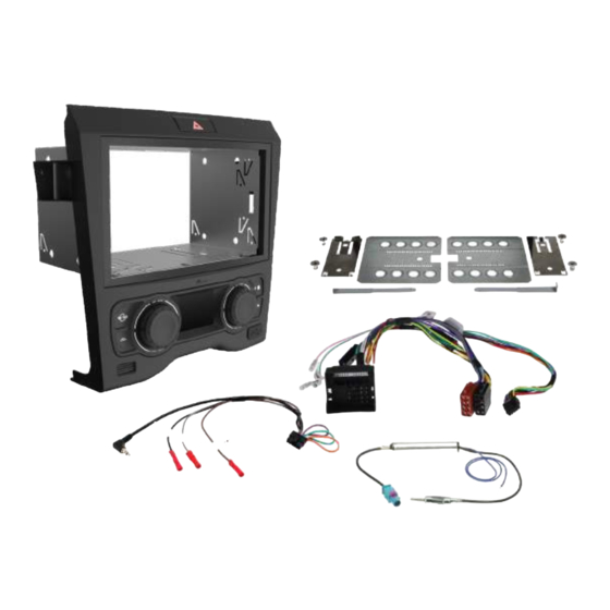
Product overview The Aerpro FP9450BK/GK VE Facia Installation Kit is Australian designed and engineered and has been made for fitting a double DIN aftermarket radio, CD or DVD player to the original double DIN enclosure. It suits VE series 1 dual climate models with full digital climate control. -
Page 4: Product Structure
Product structure Product structure 1. Front/Rear demister air button 1. Front/Rear demister air button 5. Recirculated air on/off button 5. Recirculated air on/off button 2. Left rotary dial button (Rotate,Tap,Hold) 2. Left rotary dial button (Rotate,Tap,Hold) 6. LCD display information screen 6. - Page 5 Functions Turning air-conditioning ON/OFF Once powered up, tap and hold the right rotary dial button to turn the air-conditioner on. The LCD screen illuminates and the air-conditioner icon (Snowflake) illuminates. Tap and hold again to turn off. When turning on the air-conditioner the system will remember your previous user settings.
- Page 6 Positioning To select different air positions in the vehicle tap the RIGHT rotary button. Positions are for the Head/Feet, Chest, Chest/Feet and Feet (See icons below).
- Page 7 Functions Recirculation/Air Passthrough button Tap this button to cycle between Recirculation and Air Passthrough. The corresponding icon will illuminate.
- Page 8 Functions Front/Rear demister button When air-conditioner is turned on tap this button to active Rear Demister or hold this button to activate the Front Demister. HOLD Hold Re-Calibrating your HVAC System In the case that you may need to re-calibrate you heater valves or ducting positions.
- Page 9 Functions Fan speed To adjust the fan speed tap on either of the two right buttons. Top to increase fan speed and Bottom to lower fan speed. Air-conditioner temperature Turn the right rotary dial to the left or right to lower and raise the air-conditioner temperature.
- Page 10 Functions Automatic climate control To activate auto climate mode, tap the left hand rotary dial and then set the target temperature by rotating the right hand rotary dial to the desired level. The fans speed, the vent temperature and the air flow direction is fully automatic and will adjust itself based on what it needs to get to the required level.
- Page 11 Functions Automatic climate control continued When in Auto mode (SZ or DZ), the system is equipped with 3 levels of fan speeds. Fan LOW, Fan MID and Fan HIGH Fan LOW Fan MID Fan HIGH To adjust the levels use Fan Up and Fan Down *NOTE* If you change the Vents while in Auto Climate, the vents will change, however the...
- Page 12 Functions Dual Zone Holding or turning the LEFT rotary dial will activate Dual Zone. The Single Zone temperature symbol will change to the Dual Zone temperature symbols. Adjusting Temperature To adjust the temperature of each zone, rotate the dials. Left for passenger temperature and Right for drivers side temperature Passenger Driver...
- Page 13 Functions Dual Sync When the Dual Zone if first activated, the Driver and Passenger temps will be in sync. While they are in sync, both temps can be adjusted by the drivers dial Rotate Dual Zone When the LEFT rotary dial is rotated, the passenger temp will be adjusted. Once this is done, Dual Sync will turn off and both temps can be adjusted independently Rotate...
- Page 14 Functions Anti-Pollution Mode Anti-Pollution mode will automatically switch between Passthrough and Re-Circulation based on the vehicles speed. This is to avoid the vehicle drawing in unwanted fumes when travelling at low speeds Hold Activating Anti-Pollution Mode To activate Anti-Pollution Mode, set the vehicle to Passthrough.
- Page 15 Functions Steering Wheel Control (SWC) The climate controls can also be controlled via the steering wheel controls. To activate the steering wheel mode tap the LEFT dial button. AUDIO TRIP AUDIO TRIP Single Zone When in Single Zone the Left scroll wheel controls the fan speed and the Right scroll wheel controls temperature Dual Zone When in Dual Zone the Left and Right scroll wheels control the temperature...
- Page 16 Functions Left scroll wheel Use the left scroll wheel to go up and down through audio tracks and radio stations. Audio button Press to select audio source. Trip button Press to access centre cluster settings. Phone button AUDIO • Single press to answer a call •...
- Page 17 Functions Dash Disassembly Parking Sensors Parking sensors are retained if your vehicle had them fitted from factory. The screen will automatically display the parking sensors when the vehicle is in Reverse or if the vehicle is travelling less that 15km/h Front Sensors The Front sensors are displayed at the top of the screen.
-
Page 18: Resetting The System
Resetting the system In the case of the system locking up or not functioning correctly, the unit can be reset to factory settings. Press & hold both left & right rotary knobs at the same time. Press Press & Hold &... -
Page 19: Installation
INSTALLATION... -
Page 20: Installation Information
If the system is deemed to be operational, Please continue with your Installation NOTE: Remove any Cd’s in the from the factory head unit before uninstalling Product and Install Information digital copy of this manual, please visit the aerpro.com website and search for your model or scan the QR code below. FP9450BK... -
Page 21: Tools Needed
Tools Needed Use the following tools to make dismantling the car and the installation of the new facia easier 1. Panel Remover 2. Phillips Head Screwdriver 4. Cordless Drill with 3/8” Drill Bit 3. Flat Head Screwdriver 5. Small Pick 6. -
Page 22: Dash Disassembly
Dash Disassembly Remove right side dash trim Insert a panel remover and lever towards you Remove right side dash trim Place trim aside safely until trim reassembly... - Page 23 Dash Disassembly Remove left side dash trim Insert a panel remover and lever towards yourself Remove left side dash trim Place trim aside safely until trim reassembly...
- Page 24 Dash Disassembly Remove left side screw cover trim Insert a panel remover or pick and unclip the left side screw cover Remove boot button trim Insert a panel remover or pick and unclip the boot button trim...
-
Page 25: Functions And Settings
Functions and settings Remove left side dash end trim Insert a panel remover and lever outwards to remove trim. Place trim aside safely until reassembly Remove glovebox Unclip the panel underneath the glovebox and place aside until reassembly... - Page 26 Dash Disassembly Remove glovebox There are 2x screws to remove at the bottom of the Glovebox as indicated Remove glovebox There are 5x screws to remove from around the top of the glovebox CAUTION Glovebox may drop when screws are removed...
- Page 27 Dash Disassembly Remove glovebox Once the glovebox is unscrewed, disconnect the connector at the rear to completely remove the glovebox from the vehicle Remove glovebox The connector sits behind a metal plate with a cutout to access the clip...
- Page 28 Dash Disassembly Remove left side center console trim The trim is held in with 2x clips. Remove the panel by unclipping as shown Pull directly out Pull Down Remove left side center console trim Once removed, place aside for reassembly...
- Page 29 Dash Disassembly Disconnect Antenna Most vehicles have 1x antenna connector. This vehicle has a dual cord antenna connection as shown Disconnect Antenna Press down on the top of the connector to remove from the headunit...
- Page 30 Dash Disassembly Remove right side dash end trim Insert a panel remover and lever outwards to remove trim. Remove right side dash end trim Place trim aside safely until reassembly 2-10...
- Page 31 Dash Disassembly Remove under steering wheel cover Insert a panel remover and lever downwards to remove trim remembering to do the same thing on the left side of the steering wheel as well Remove under steering wheel cover While unclipping, be sure to hold up the panel and not let it drop to protect the headlight switch connection 2-11...
- Page 32 Dash Disassembly Remove right side center console trim The trim is held in with 2x clips. Remove the panel by unclipping as shown. Place the trim aside until reassembly Pull Down Pull directly out Disconnect the factory radio connector Now that the trims are removed, the factory stereo can be removed 2-12...
- Page 33 Dash Disassembly Unplug the radio connector To remove the connector, pinch the top clip and pull the handle backwards to release the connector EXAMPLE Unplug the radio connector Once all connectors have been disconnected, the radio is free to be removed 2-13...
- Page 34 Dash Disassembly Remove the factory radio face panel The factory face panel is held on with 4x clips. Start by unclipping the bottom using your hands or panel remover, then unclip the top Remove the factory radio face panel You will feel the face panel come lose when the clips have released 2-14...
- Page 35 Dash Disassembly Remove the factory radio There are 4x screws to remove as indicated below Bottom compartment with closing lid If your vehicle is fitted with a center compartment with a closing lid, you may want to replace this with the non lid version (not supplied) with the following steps If this does not apply to you, skip to page 2-21 2-15...
- Page 36 Replacing Compartment Bottom compartment with closing lid Using a panel remover, unclip the trim around the gear stick Bottom compartment with closing lid Place the trim aside for reassembly 2-16...
- Page 37 Replacing Compartment Bottom compartment with closing lid Using a panel remover, unclip around the window switches Bottom compartment with closing lid Continue unclipping the panel by working your way up until the panel is removed 2-17...
- Page 38 Replacing Compartment Bottom compartment with closing lid Once the panel is able to be moved out of the way, you will have access to the bottom compartments screws Bottom compartment with closing lid Remove the 2x screws holding in the bottom compartment 2-18...
- Page 39 Replacing Compartment Bottom compartment with closing lid Once the screws are removed, the compartment is then only held in by 2x clips. Unclip the compartment and place aside Bottom compartment with closing lid The clips are on the rear as shown 2-19...
- Page 40 Replacing Compartment Bottom compartment with closing lid Clip the replacement compartment without the lid (Holden Part no. 92167863) in place (This is not supplied with this kit) Bottom compartment with closing lid Screw it into place using the screws which were removed 2-20...
- Page 41 Facia Kit Installation Bottom compartment with closing lid Re-Install the removed panels to complete the compartment swap Mounting the new facia kit (continued) Now that the factory radio has been removed and the compartment swapped, you are free to begin installing the new radio. Remove the 2x screws shown below 2-21...
- Page 42 Facia Kit Installation Mounting the new facia kit Before you mount the new kit into your vehicle, plug in the supplied harnesses to the rear of the facia. 1x Power harness and 1x Steering wheel control harness Mounting the new facia kit Connect the supplied antenna adaptor to the factory antenna connector 2-22...
- Page 43 Facia Kit Installation Mounting the new facia kit Feed all your wiring out of the front of the facia to ensure nothing is trapped behind. The large connector should go out the right side to where the factory connector is Mounting the new facia kit Push the kit into place and screw into place using the screws removed previously 2-23...
- Page 44 Facia Kit Installation Mounting the new facia kit Pre drill the bottom mounting hole using a 3/8 drill bit and screw into place using the supplied screw *NOTE* For Some models, use the supplied spacer and longer screw Mounting the new facia kit Now that the new kit is mounted to the car, you can install the new headunit 2-24...
- Page 45 Facia Kit Installation Mounting the new facia Slide the mounting cage into place ensuring all the cables which will plug into the new radio are fed out the front Mounting the new facia Using a large flat head screw driver, bend the triangle tabs to lock the cage in place 2-25...
- Page 46 Facia Kit Installation Mounting the new facia kit The mounting brackets have spring locators that lock into cut outs in the cage. Knowing that the cage cut outs are 18mm back from the edge of the facia trim will help you determine where to mount the brackets EXAMPLE Mounting the new facia kit Align the bracket on the headunit and then set the depth using the slider clip...
- Page 47 Facia Kit Installation Testing the system before completing installation Once the brackets are mounted, slide the headunit into the cage, but not the whole Testing the system before completing installation Connect the quadlock connectors together and turn the key to ‘Ignition’ 2-27...
- Page 48 Facia Kit Installation Completing installation Once fully powered, check the functionality of the stereo and the facia kit Testing the system before completing installation When the kit is first powered up, it is best to do a hard reset by pushing both dials in together.
- Page 49 Facia Kit Installation Completing installation Push the headunit in until the brackets clip into place, then insert the supplied trim Completing installation Reassemble the vehicles trims in the reverse order to the disassembly to finish the installation 2-29...
-
Page 50: Wiring Diagram
Wiring Diagram Reverse Camera Aftermarket Unit Vehicle Retention Harness Camera in Harness Antenna in Remote in Secondary Harness Vehicle Harness Main Harness Antenna booster Power (Blue) Park brake (Green) Vehicle Harness Reverse (Purple) Speed Pulse(Pink) Highlighted Yellow Not Included (Sold Separately) 2-30... - Page 51 Previously the Sony used the Pioneer/Sony config but if this is not working then changing to this new config should allow the phone button to work. PLEASE NOTE: Remove power from the Aerpro kit (unplug main quadlock plug) before changing patch lead configurations. This will allow the kit to reset its programming.
-
Page 52: Technical Assistance
Technical assistance If you need assistance setting up or using your Aerpro product now or in the future, call Aerpro Support. Australia TEL: 03 – 8587 8898 FAX: 03 – 8587 8866 Mon-Fri 9am – 5pm AEST Please retain this user guide for future reference.
Need help?
Do you have a question about the FP9450GK and is the answer not in the manual?
Questions and answers