Advertisement
Quick Links
Features
Easy Embedded Remote Control
•
4 digital outputs
•
Serial Data output
•
Minimal external components
•
Secure data protocol
•
Ultra low power 1.8—3.6V
•
Easy pairing process
•
-121dBm Receive Sensitivity
•
Range when used with:
•
FOBBER Keyfob up to 200metres
•
TRAP Handset up to 1000metres
•
ZPT-T up to 2000m
•
SABRE Handset up to 2000metres
•
SMT or SIL package
•
self test mode Incorporated
•
CE compliant for EU licence free use
•
Description
FOBOEM provides an easy "plug and Play" Remote Control.
The ZPT Receiver module is an easy design into any circuit, and requires very few ad-
ditional components. When incorporated the ZPT Receiver module automatically out-
puts the serial data of any FOBBER Keyfob. Using the Easy LEARN Process
the ZPT can be paired with many FOBER keyfobs, which, when operated will cause
the ZPT Digital outputs to be activated.
Part Numbers
Part No
FOBOEM-4S4
FOBOEM-8S4
FOBOEM Telemetry system
4 Switch Fob, SMT ZPT Receiver module with pins Bundled 433MHz
4 Switch Fob, SMT ZPT Receiver module with pins Bundled 868MHz
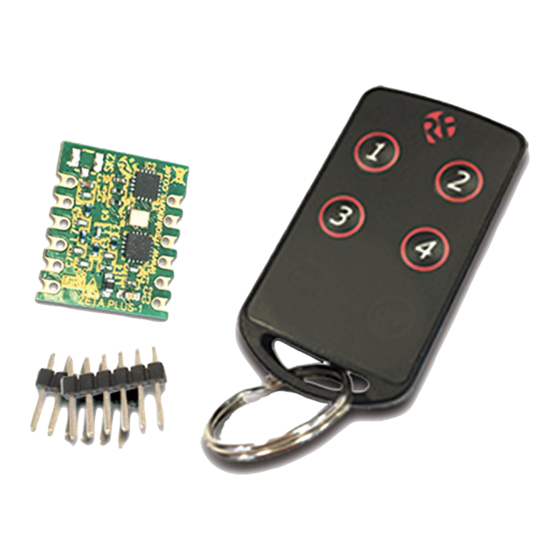
DS-FOBOEM-2
ZPT Module
Header Pins
Applications
Remote control
•
I/O Telemetry devices
•
Remote switching
•
Remote traffic lights
•
Description
FOBBER-8T4
Advertisement

Subscribe to Our Youtube Channel
Related Manuals for RF SOLUTIONS FOBOEM-4S4


Summary of Contents for RF SOLUTIONS FOBOEM-4S4
- Page 1 ZPT can be paired with many FOBER keyfobs, which, when operated will cause the ZPT Digital outputs to be activated. Part Numbers Description Part No FOBOEM-4S4 4 Switch Fob, SMT ZPT Receiver module with pins Bundled 433MHz FOBOEM-8S4 4 Switch Fob, SMT ZPT Receiver module with pins Bundled 868MHz DS-FOBOEM-2...
- Page 2 FOBOEM Telemetry system Compatible Transmitters The ZPT module can be used with the transmitters below, The transmitter handset will affect the maximum achievable range of operation. FOBBER Keyfob Compact rugged handset Waterproof to IP68 1,2,3,4,6,8 button Options Operating up to 200m TRAP Handset A medium sized rugged handset available as 1,2,3,4,6,8,16 buttons...
-
Page 3: Pin Description
FOBOEM Telemetry system Pin-out O/P1 O/P2 O/P3 SLEEP O/P4 LED/LRN MOM / LAT SERIAL O/P Pin Description Pin No Name Direction Description Antenna input/output 50ohm impedance Connect to ground to GND, Module active SLEEP Connect to Vcc, Module Enters SLEEP Supply voltage Learn switch input and LED output LED/... - Page 4 FOBOEM Telemetry system Operation The ZPT module will remain in a low power listening mode at all times when power is present and the Sleep Input is Low. When a valid RF signal is received ZPT will wake and process the RF packet.
- Page 5 FOBOEM Telemetry system ZPT Receiver module serial data output The ZPT outputs the serial number, button and battery status of the transmitter encoder. This data may be fed directly to a microcontroller or RS232 type driver circuit which may then be fed directly to a PC serial port.
- Page 6 FOBOEM Telemetry system ZPT example application circuit Output 1 Output 2 Output 3 Output 4 560R Serial Learn Output Learn switch Description: This example shows a ZPT module receiver with all 4 outputs connected. Note: The external learn switch and learn LED are both shown connected in this example. ZPT connected with Serial data output via MAX232 100nF MAX232...
- Page 7 FOBOEM Telemetry system Self Test Mode ZPT module incorporates a self test which is initiated by applying power with the learn button held down. The module then performs the following functions: All outputs operate in turn ON/OFF twice All outputs flash ON/OFF 5 times - 1&3 and then 2&4 Transmits a full power RF signal for 5 seconds while flashing the learn LED Enters RSSI (Received Signal Strength Indication) mode where outputs 1-4 are activated as a bar graph type output according to the strength of a valid RF signal received (from...
- Page 8 FOBOEM Telemetry system Mechanical dimensions Surface Mount Package 3.00 PCB pad Layout 2.00 1.00 13.00 D 1.00 17.50 16.50 D Package 13.00 D 1.00 16.50 0.65 DS-FOBOEM-2...
- Page 9 FOBOEM Telemetry system ZPK module re-flow guide Profile feature Value (lead free) Ramp up rate C /s Pre-heat temperature - Temperature Min (T Smin - Temperature Max (T smax - Pre-heat time 60-100s Peak temperature (T Time at T 10-20sec Ramp down rate Time from 25 C to peak...
-
Page 10: Electrical Characteristics
FOBOEM Telemetry system Electrical Characteristics Notes Symbol Parameter Ambient Tempera- ture Supply Voltage I/O Drive Voltage GPIO Operating Fre- 868MHz version 896.500 915. 915. quency 915MHz version -121 RX Sensitivity DC characteristics Parameter Symbol Test Typ. Max Unit Supply voltage range Module asleep with shutdown pin active. - Page 11 Disclaimer: Whilst the information in this document is believed to be correct at the time of issue, RF Solutions Ltd does not accept any liability whatsoever for its accuracy, adequacy or completeness. No express or implied warranty or representation is given relating to the information contained in this document. RF Solutions Ltd reserves the right to make changes and improvements to the product(s) described herein without notice.
Need help?
Do you have a question about the FOBOEM-4S4 and is the answer not in the manual?
Questions and answers