RF SOLUTIONS TRAP Series Manual
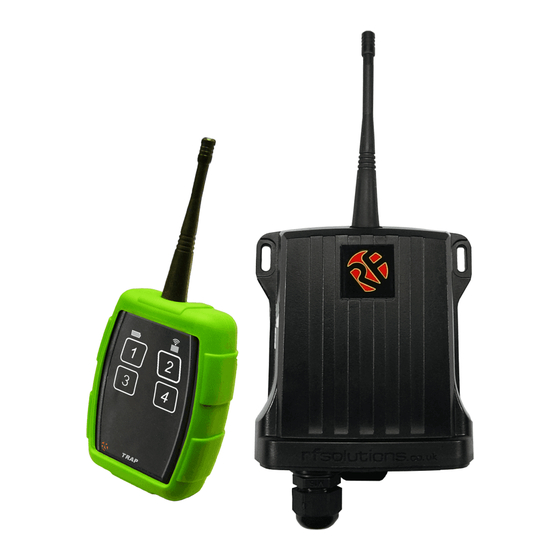
2km range rugged remote control
Hide thumbs
Also See for TRAP Series:
- Manual (11 pages) ,
- Quick start manual (6 pages) ,
- Quick start manual (4 pages)
Advertisement
Features
1 - 4 Channels Each Rated1KW
•
Map any Tx Switch to Any RX O/P
•
Relay Changeover Contacts Rated 5A
•
@ 230Vac (1KW)
868 / 918MHz FM Technology
•
Transmitter
IP66 Rated
•
Powered from 3 x AAA Batteries
•
LED Acknowledgment Back from Rx
•
Continuous / State change Transmit
•
Receiver
6-32Vac/dc Supply
•
Waterproof Receiver (IP68)
•
Outputs Momentary or Latching
•
Optional Rx Acknowledge back to
•
Transmitter
Optional External Antenna mount
•
Systems supplied 'ready to Go'
•
Description
A versatile general purpose Remote Control System for many different applications.
Housed in a rugged IP68 weatherproof enclosure, The TRAP system is ideally suited to any
outside Remote switching. Receivers have 4 relay outputs, using the 'easy-learn' process
each output can be controlled from one or many switches form one or many transmitters.
2KM Range Rugged Remote Control
DS TRAP-10
TRAP Series
Applications
General Purpose Remote Switching
•
Industrial switching, conveyors,
•
machinery, pumps
Clay Pigeon Release
•
Most known Lighting types (LED,
•
fluorescent, halogen, tungsten, xenon).
Advertisement
Table of Contents

Related Manuals for RF SOLUTIONS TRAP Series


Summary of Contents for RF SOLUTIONS TRAP Series
- Page 1 TRAP Series 2KM Range Rugged Remote Control Features 1 - 4 Channels Each Rated1KW • Map any Tx Switch to Any RX O/P • Relay Changeover Contacts Rated 5A • @ 230Vac (1KW) 868 / 918MHz FM Technology • Transmitter IP66 Rated •...
-
Page 2: Ordering Information
TRAP Remote Controls Ordering Information Receiver 868MHz 918Hz Description Version Version Power Supply System 1 channel TRAP-8S1 TRAP-9S1 12-30Vac or dc System 4 channel TRAP-8S4 TRAP-9S4 System 1 channel TRAP-8S1M 230Vac System 2 channel TRAP-8S2M Additional Transmitters 868MHz 918MHz Transmitter Version Version 1 Switch... -
Page 3: Installation
TRAP Remote Controls Installation Below is a simple example showing one possible way to wire a relay in order to give switched power to an external load: When the relay is energised the ‘COM’ connects to ’NO’ and power is applied to the Load. Open the enclosure by removing fixing screws from the enclosure Remove the antenna and slide out the circuit board. -
Page 4: Receiver Configuration
TRAP Remote Controls Receiver Configuration The link pins LK1 and LK2 set the action of the relays sec Mom = Relay will operate for = Relay will operate for as long as transmitter switch operated Latch = Relay will toggle ON/OFF on each transmitter button press 12-30V Version Link Pins LED s... -
Page 5: Transmitter Operation
TRAP Remote Controls Transmitter Operation Press any of the switches to operate. The Transmitter will auto sleep between operations to save power The LED’s indicate the following: RF Transmit (Green LED) RF Transmit GREEN LED operates when transmitting an RF Battery RF Acknowledge signal... - Page 6 TRAP Remote Controls Configure Transmitter to request Acknowledge from Press SET Sw Receiver Acknowledgement Feature provides the user with LED indication that the receiver has successfully received the transmitters signal. LED1 flashes 1x When activated the Transmitter includes an acknowledgement request from the receiver within each radio transmission.
- Page 7 TRAP Remote Controls Advanced operation - Pairing a Transmitter Button With this system, you can pair together any individual trans- mitter switch with any receiver relay switch. Without opening either enclosure: Remove the green transmitter rubber over-boot Briefly (~1 second) place the transmitter next to the re- ceiver in the position shown and then remove it.
-
Page 8: Connecting An External Antenna
TRAP Remote Controls Connecting an External Antenna External Antenna Connector (ANT2) An External Antenna maybe connected into connector ANT2. A direct plug in coax Cable is available to convert this to Standard SMA type connector CBA-UFLSMA Push fits onto the External antenna Connector and provides a panel mount SMA connector which ena- ble many types of antenna to be connected. -
Page 9: Mechanical Dimensions
TRAP Remote Controls Technical specifications Transmitters: TRAP-Transmitter Enclosure Rating: Standard IP65 (upgradeable to IP68) Battery Type: 3 x AAA (supplied) Battery Life: 2 years @ approx. 50 1/2second presses p/day Dimensions: 90 x 54 x 27 mm Changing the Battery: Remove the six enclosure screws. Remove 2 battery compartment screws and re- place batteries, taking care of cables and battery polarity Electrical Characteristics Typical... -
Page 10: Technical Specifications
TRAP Remote Controls Technical specifications Receiver Decoder: TRAP-Receiver Enclosure Rating: IP68 Dimensions: 130 x 112 x 42 mm (not including antenna) Operating Temperature: -10 to +50 Celsius. Electrical Characteristics TYPICAL DIMENSION Supply Voltage Vdc or ac Supply Voltage for 230Vac Relay Rating* (230Vac) Supply Current at Vsupply 12V Quiescent... - Page 11 TRAP Remote Controls Range Test Notes Our Range Testing was conducted on Ditchling Beacon providing an open Line of Sight Test. Receiver was placed on our vehicle in the Beacon Car park The transmitter was carried along the beacon whilst being repeatedly operated. At full distance the Transmitter was also tested while placed on the ground.
- Page 12 Disclaimer: Whilst the information in this document is believed to be correct at the time of issue, RF Solutions Ltd does not accept any liability whatsoever for its accuracy, adequacy or completeness. No express or implied warranty or representation is given relating to the information contained in this document. RF Solutions Ltd reserves the right to make changes and improvements to the product(s) described herein without notice.
Need help?
Do you have a question about the TRAP Series and is the answer not in the manual?
Questions and answers