
Related Manuals for Elo TouchSystems Entuitive ET1529L Series


Summary of Contents for Elo TouchSystems Entuitive ET1529L Series
-
Page 1: User Guide
Elo Entuitive Touchmonitor User Guide For 15” LCD Desktop ET1529L Series Revision.B... - Page 2 Elo Entuitive Touchmonitor User Guide 15" LCD Desktop ET1529L Series Revision B P/N 008603 Elo TouchSystems, Inc. 1-800-ELOTOUCH www.elotouch.com...
- Page 3 Elo TouchSystems reserves the right to revise this publication and to make changes from time to time in the content hereof without obligation of Elo TouchSystems to notify any person of such revisions or changes.
-
Page 4: Table Of Contents
Table of Contents Chapter 1 Introduction Product Description ... 1 Detailed LCD Display Performance Requirements ... 2 Customer Display ... 4 Serial Version ... 4 Fingerprint Reader ... 4 Theory of Operation ... 5 Sensor Specifications ... 5 Credit Card Reader ... 5 Six Port USB Hub ... - Page 5 AccuTouch Touchscreen Specifications ... 47 IntelliTouch Touchscreen Specifications ... 48 Infrared Touchscreen Specifications ... 49 15” LCD Touchmonitor (ET1529L-XXXA-1-XX) Dimension ... 50 15” LCD Touchmonitor (ET1529L-XXXA-1-C3/C4-XX) Dimension ... 50 15” LCD Touchmonitor (ET1529L-XXXA-1-XX-T) Dimension ... 50 Regulatory Information Warranty Index...
-
Page 7: Introduction
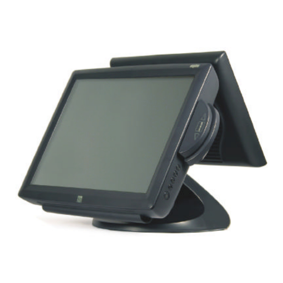
NTRODUCTION Product Description The ET1529L is a retail terminal designed to present information to the operator and the customer. The ET1529L is available in serial and USB versions or combo touch monitor. The ET1529L functionally consists of a 15.0” LCD main display with a touchscreen, an optional 12.1 inch Lcd, customer display, an optional vacuum fluorescent display (VF D) -
Page 8: Detailed Lcd Display Performance Requirements
The credit card reader reads all three stripes on a standard credit card or drivers license. The credit card is read by sliding the credit card, stripe side toward the display through the credit card reader forward or backward. There is a USB credit card reader only. The Hub provides 4 internal USB ports to be used by the credit card reader, the finger- print reader, the touchscreen, and the customer display. - Page 9 12.1 Customer Display TFT LCD Display Panel Display Format 800x600 Display area 12.1” 246.0mm(H) x 184.5mm(V) Pixel Pitch 12.1” 0.3075mm(H) x 0.3075mm(V) Contrast Ratio 150:1(Min) Brightness 180 cd/m 165cd/m IntelliTouch Transmission 92% typical Horizontal Viewing Angle +/- 45 degree typical at CR=10 Video Interface Connector -30/+10 degree typical at CR=10 (Typical) with no touchscreen...
-
Page 10: Customer Display
Customer Display The Customer Display is a twenty character two line vacuum fluorescent display (VF D). It consists of a VF D and VF D controller. Serial Version Optional Parameters Characters per row Number of rows Character configuration Character Height Character width Character configuration... -
Page 11: Theory Of Operation
Specifications Sensor Image Capture Speed Image Transfer Speed Pixel Resolution USB Signaling Type Theory of Operation The USB host initiates communication with the F DU01 using operation commands (Sensor LED On, Fingerprint Capture Start and Stop). Fingerprint data are then cap- tured by the CMOS sensor at a total image size of 356 x 292 with 8-bit gray level. -
Page 12: Six Port Usb Hub
Six Port USB Hub The Hub provides 4 internal USB ports to be used by the credit card reader, the finger- print reader, the touchscreen, and the customer display. The hub also supplies two USB ports to the outside of the back of the 1529L for external use. The hub is only used by the USB version of the 1529L. -
Page 13: Installation And Setup
This chapter discusses how to install your LCD touchmonitor and how to install Elo TouchSystems driver software. Unpacking Your Touchmonitor Check that the following items are present and in good condition: Touchmonitor Video cable DVI cable NSTALLATION AND Touchmonitor with 12CD Power cable US/Candian Speaker CD and Quick Install Guide... -
Page 14: Product Overview
Product Overview Main Unit Rear View 2-8 Elo Entuitive Touchmonitor User Guide... -
Page 15: Side View
Side View Base Bottom View... -
Page 16: Kensington Lock
Kensington Lock The Kensington lock is a security device that prevents theft. To find out more about this security device, do to http://www. kensington.com. 2-10 Elo Entuitive Touchmonitor User Guide... -
Page 17: Usb Interface Connection
USB Interface Connection Your touchmonitor comes with only one touchscreen connector cables: USB cable. (For Windows 2000, Me and XP systems only.) To set up the display, please refer to the following figures and procedures: Remove the Cable Cover The cables are connected at the back of the monitor. cable cover To remove the cover, grasp the lip of the cover and pull towards you until it snaps off. - Page 18 AUTION Before connecting the cables to your touchmonitor and PC, be sure that the computer and touchmonitor are turned off. Before connecting the cables to the touchmonitor, route all the cables through the hole in the second as shown in the pictire above. 2-12 Elo Entuitive Touchmonitor User Guide...
- Page 19 The following illustrations guide you step by step in connecting your touchmonitor using a USB cable connection. Power cord Connect one end of the power cord to the monitor and the other end to wall. Connect the power cable to the power port in the monitor. 2-13...
- Page 20 Connect one end of the video cable to the rear side of computer and the other to the LCD. Tighten by turning the two thumb screws clockwise to ensure proper grounding. You can select DVI video cable or D-SUB15 video cable. 2-14 Elo Entuitive Touchmonitor User Guide Video cable DVI cable...
- Page 21 Speaker cable Connect one end of the speaker cable to the speaker port in the computer and the other end to the port in the monitor. 2-15...
- Page 22 USB cable Connect one end of the USB cable to the rear side of the computer and the other to the LCD monitor. The USB cable is for optional touch, MSR, CD and Finger Print Reader. Only one USB cable is needed because the device contains a self powered USB 1.1 Hub. Two self powered ports are available for running other USB devices.
-
Page 23: Replace The Cable Cover
Replace the Cable Cover Cable cover lip cables Then you have attached all the cables to the monitor, gently bring all the cables toward the standard so they fit under the cover lip. Snap the Cable cover in place over the connections. 2-17... -
Page 24: Optimizing The Lcd Display
Optimizing the LCD Display To ensure the LCD display works well with your computer, configure the display mode of your graphic card to make it less than or equal to 1024 x 768 resolution, and make sure the timing of the display mode is compatible with the LCD display. Refer to Appen- dix A for more information about resolution. -
Page 25: Magnetic Stripe Reader
Magnetic Stripe Reader No device are needed. Testing the USB MSR Keyboard Emulation 1 Plug in the device. 2 Open MS Word. 3 Slide the card through the MSR to view the data. Testing the USB-HID Class MSR 1 On the CD, browse to Touch Monitor Peripherals\Magnetic Stripe Card Readers\Demo. - Page 26 This dialog will appear 1.6 Swipe Test card. Close Read Cards Dialog. Click on Send Command. The following dialog box will appear To send Inquiry MSR type 1.10 Type 00 10 into area under the heading Message(Hex) 2-20 Elo Entuitive Touchmonitor User Guide...
- Page 27 1.11 Then click on Send Message. 1.12 The DATA=00 means it’ s USB HID. 1.13 Switch to Keyboard Emulation 1.14 Type 01 10 01 into area under the heading Message(Hex) 1.15 Then click on Send Message. 1.16 Send Inquiry MSR type 1.17 Type 00 10 into area under the heading Message(Hex) 1.18...
-
Page 28: Convert Msr From Keyboard Emulation To Hid
1.19 The DATA=01 means it’ s USB Keyboard Emulation. 1.20 You must now reset the MSR by sending the command 02. 1.21 Type 02 into area under the heading Message(Hex) 1.22 Then click on Send Message. 1.23 Double click on The KB MSR Test icon in the desktop and slide the test c card. The following icon will appear 1.24 Done. - Page 29 1.2 click on About to verify version 1.3 Close About Dialog. 1.4 Click on Send Commands 1.5 This Dialog will appear. 1.6 To send Inquiry MSR type 1.7 Type 00 10 into area under the heading Message(Hex) 1.8 Then click on Send Message. 2-23...
- Page 30 The DATA=01 means it’ s USB Keyboard Emulation. 1.10 Switch to HID 1.11 Type 01 10 00 into area under the heading Message(Hex) 1.12 Then click on Send Message. 1.13 Send Inquiry MSR type 1.14 Type 00 10 into area under the heading Message(Hex) 1.15 Then click on Send Message.
- Page 31 1.19 Click on Read Cards… 1.20 This dialog will appear 1.21 Swipe Test card. 1.22 Cose Read Cards Dialog. 1.23 Done. 2-25...
-
Page 32: Rear Facing Customer Display
Rear Facing Customer Display USB Customer Display Plug in the USB cable attached to the Customer Display unit. The New Hardware Wiz- ard dialog box will appear. 1 Choose Next and select “Search for the best driver for your device (Recommended) ”... -
Page 33: Installing The Touch Driver Software
•MS DOS •OS/2 Additional drivers and driver information for other operating systems (including Macintosh and Linux) are available on the Elo TouchSystems web site at www.elotouch. com. Your Elo USB touchmonitor is plug-and-play compliant. Information on the video capa- bilities of your touchmonitor is sent to your video display adapter when Windows starts. -
Page 34: Installing The Usb Touch Driver
3 When a list of search locations is displayed, place a checkmark on “Specify a location” and use Browse to select the \EloUSB directory on the Elo CD-ROM. 4 Choose Next. Once the Elo TouchSystems USB touchscreen driver has been detected, choose Next again. -
Page 35: Operation
C H A P T E R PERATION About Touchmonitor Adjustments Your touchmonitor will unlikely require adjustment. Variations in video output and ap- plication may require adjustments to your touchmonitor to optimize the quality of the display. For best performance, your touchmonitor should be operating in native resolution, that is 1024x768 at 60-75 Hz. -
Page 36: 15.0" Lcd Function Key
15.0” LCD Function Key Controls Power Switch Select Menu 3-30 Elo Entuitive Touchmonitor User Guide Function Turns the display system power on or off. Displays the OSD menus on the screen and used to select (“Clockwise” and “Counter-clockwise” direction) the OSD control options on the screen. -
Page 37: Controls And Adjustment
Controls and Adjustment OSD Lock/Unlock You are able to lock and unlock the OSD feature. The monitor is shipped in the unlocked position. To lock the OSD: 1 Press the Menu button and appear displaying “OSD Unlock”. Continue to hold the buttons down for another 2 seconds and the window toggles to “OSD Lock”. -
Page 38: Osd Control Options
OSD Control Options Brightness • Background Luminance of the LCD panel is adjusted. Contrast • Adjusts the contrast or the values of color gain (RED, GREEN or BLUE). Saturation, Hue, Flesh Tones • Adjusts the color intensity and tint so faces appear natural. Phase •... -
Page 39: Language
Language • Languages used for OSD menu display: English, French, German, Spanish and Japanese. Recall Defaults • Recalls the factory OSD default settings. OSD Timeout • Adjusts the amount of time in which the OSD will disappear. Power-Save (No Input) •... - Page 40 CAUTION In order to protect the LCD, be sure to hold the base when adjusting the LCD, and take care not to touch the screen. 3-34 Elo Entuitive Touchmonitor User Guide...
-
Page 41: 12.1" Lcd Function Key
12.1” LCD Function Key Controls Select Menu Function Displays the OSD menus on the screen and used to select (“Clockwise” and “Counter-clockwise” direction) the OSD control options on the screen. Adjusts the decreasing value of the selected OSD control option. Adjusts the increasing value of the selected OSD control option. -
Page 42: Controls And Adjustment
Controls and Adjustment OSD Lock/Unlock You are able to lock and unlock the OSD feature. The monitor is shipped in the unlocked position. To lock the OSD: 1 Press the Menu button and appear displaying “OSD Unlock”. Continue to hold the buttons down for another 2 seconds and the window toggles to “OSD Lock”. -
Page 43: Osd Control Options
OSD Control Options Brightness • Background Luminance of the LCD panel is adjusted Contrast • Gain of R, G, and B signal is adjusted. Phase • The phase of the dot clock is adjusted. Auto Adjust • Automatically adjusts the systems dot clock(takes approximately 5 seconds). OSD Left/Right •... -
Page 44: Language
Language • Select the language used for the OSD menu from among English, French, Deutsch, Spanish, and Japanese. Recall Defaults • Restore all original factory defaults. OSD Timeout • Adjust how long the OSD menu is displayed. OSD Exit • Exit’ s the OSD menu. 3-38 Elo Entuitive Touchmonitor User Guide... -
Page 45: Solutions To Common Problems
If you are experiencing trouble with your touchmonitor, refer to the following table. If the problem persists, please contact your local dealer or our service center. Elo Techni- cal Support numbers are listed on the last page of this manual. Solutions to Common Problems Problem The monitor does not respond after... - Page 46 4-40 Elo Entuitive Touchmonitor User Guide...
-
Page 47: Appendix A Native Resolution
The native resolution of a monitor is the resolution level at which the LCD panel is designed to perform best. For the Elo LCD touchmonitor, the native resolution is 1024 x 768 for the 15.0 inch size. In almost all cases, screen images look best when viewed at their native resolution. - Page 48 As an example, a SVGA resolution LCD panel has 800 pixels horizontally by 600 pixels vertically. Input video is also represented by the same terms. XGA input video has a format of 1024 pixels horizontally by 768 pixels vertically. When the input pixels con- tained in the video input format match the native resolution of the panel, there is a one to one correspondence of mapping of input video pixels to LCD pixels.
-
Page 49: Touchmonitor Safety
Do not attempt to fit the plug into an outlet that has not been configured for this purpose. Do not use a damaged power cord. Use only the power cord that comes with your Elo TouchSystems Touchmonitor. Use of an unauthorized power cord may invalidate your warranty. -
Page 50: Care And Handling Of Your Touchmonitor
Care and Handling of Your Touchmonitor The following tips will help keep your Elo Entuitive touchmonitor functioning at the optimal level. • To avoid risk of electric shock, do not disassemble the brick supply or display unit cabinet. The unit is not user serviceable. Remember to unplug the display unit from the power outlet before cleaning. -
Page 51: Technical Specifications
Display Modes Your Elo Entuitive touchmonitor is compatible with the following standard video modes: Item Resolution Type 640X350 720X400 640X480 640X480 VESA72 640X480 VESA75 800X600 SVGA 800X600 SVGA 800X600 VESA72 800X600 VESA75 1024X768 1024X768 1024X768 VESA75 ECHNICAL H. Scan(KHz) V. Scan(Hz) 31.469 70.087 31.469... -
Page 52: Touchmonitor Specifications
Temp Humidity Dimensions (HxWxD) Weight (Net) Certifications C-46 Elo Entuitive Touchmonitor User Guide ET1529L 15.0” TFT Active Matrix Panel 304.1(H) x 228(V) mm 0.297(H) x 0.297(V) mm VGA 640 x 350 (70 Hz) VGA 720 x 400 (70 Hz) VGA 640 x 480 (60 / 72 / 75 Hz) -
Page 53: Accutouch Touchscreen Specifications
AccuTouch Touchscreen Specifications Mechanical Construction Top: Polyester with outside hard- surface coating with clear or antiglare finish. Inside: Transparent conductive coating. Bottom: Glass substrate with uniform resistive coating. Top and bottom layers separated by Elo-patented separator dots. Positional Accuracy Standard deviation of error is less than 0.080 in. (2.03 mm). This equates to less than ±1%. -
Page 54: Intellitouch Touchscreen Specifications
IntelliTouch Touchscreen Specifications Mechanical Positional Accuracy Touchpoint Density Touch Activation Force Surface Durability Expected Life Performance Sealing Optical Light Transmis sion (per ASTM D1003) Visual Resolution Gloss (per ASTM D2457 using a 60-degree gloss meter) Environmental Chemical Resistance Electrostatic Protection (per EN 61 000-4-2, 1995) C-48 Elo Entuitive Touchmonitor User Guide Standard deviation of error is less than 0.080 in. -
Page 55: Infrared Touchscreen Specifications
Infrared Touchscreen Specifications Mechanical Input Method Electrical Positional Accuracy Resolution Touch Activation Force Controller Optical Light Transmission Chemical Resistance Durability Surface Durability Input Method Finger or gloved hand activation Typical centroid accuracy: 2 mm with 1 mm STD error Touchpoint density is based on controller resolution of 4096 x 4096 No minimum touch activation force is required Board: Serial (RS232) or USB 1.1... -
Page 56: 15" Lcd Touchmonitor (Et1529L-Xxxa-1-Xx) Dimension
15” LCD Touchmonitor(ET1529L-XXXA-1-XX) Dimensions 15” LCD Touchmonitor(ET1529L-XXXA-1-C3/C4-X) Dimensions 15” LCD Touchmonitor(ET1529L-XXXA-1-XX-T) Dimensions C-50 Elo Entuitive Touchmonitor User Guide... -
Page 57: Regulatory Information
I. Electrical Safety Information: A) Compliance is required with respect to the voltage, frequency, and current require- ments indicated on the manufacturer’ s label. Connection to a different power source than those specified herein will likely result in improper operation, damage to the equip- ment or pose a fire hazard if the limitations are not followed. - Page 58 This Information Technology Equipment (ITE) is required to have a CE Mark on the manufacturer’ s label which means that the equipment has been tested to the following Directives and Standards: This equipment has been tested to the requirements for the CE Mark as required by EMC Directive 89/336/EEC indicated in European Standard EN 55 022 Class B and the Low Voltage Directive 73/23/EEC as indicated in European Standard EN 60 950.
- Page 59 "The application of this monitor is restricted to special controlled luminous environments.The screen surface trend to reflect annoying light of lamps and sunlight. To avoid these reflections the monitor should not be positioned in front of a window or directed to luminaries. The monitor is in compliance with Reflection Class III according to ISO 13406-2"...
- Page 60 Elo Entuitive Touchmonitor User Guide...
-
Page 61: Warranty
WARRANTY Except as otherwise stated herein or in an order acknowledgment delivered to Buyer, Seller warrants to Buyer that the Product shall be free of defects in materials and workmanship. With the exception of the negotiated warranty periods; the warranty for the touchmonitor and components of the product is 3 years. - Page 62 THESE REMEDIES SHALL BE THE BUYER’S EXCLUSIVE REMEDIES FOR BREACH OF WARRANTY. EXCEPT FOR THE EXPRESS WARRANTY SET FORTH ABOVE, SELLER GRANTS NO OTHER WARRANTIES, EXPRESS OR IMPLIED BY STATUTE OR OTHERWISE, REGARDING THE PRODUCTS, THEIR FITNESS FOR ANY PURPOSE, THEIR QUALITY, THEIR MERCHANTABILITY, THEIR NONINFRINGEMENT, OR OTHERWISE.
-
Page 63: Current Input
Numerics 15.0" LCD Touchmonitor (ET1529L-XXWA-1) Dimensions, 50 About Touchmonitor Adjustments, 29 AccuTouch Touchscreen Specifications, 47 Auto Adjust, 32 Base Bottom View, 9 Brightness, 32 Care and Handling of Your Touchmonitor, 44 Chemical Resistance, IntelliTouch, 48 Chemical Resistance, IR, 49 Cleaning Your Touchmonitor, 44... -
Page 64: Remove The Back Cover
Native Resolution, 41 Optical, AccuTouch, 47 Optical, IntelliTouch, 48 Optical, IR, 49 Optimizing the LCD Display, 18 OSD Control Options, 32,36 OSD Left/Right, 32,36 OSD Lock/Unlock, 31,35 OSD Menu Functions, 31,35 OSD Position, 32,36 OSD Timeout, 33,37 OSD Up/Down, 32,36 Phase, 32,36 Positional Accuracy, AccuTouch, 47 Positional Accuracy, IntelliTouch, 48... - Page 66 USB INTELLIHEAD FOR SWIPE READERS TECHNICAL REFERENCE MANUAL Manual Part Number 99875320-1P OCTOBER 2004 PRELIMINARY REGISTERED TO ISO 9001:2000 20725 South Annalee Avenue Carson, CA 90746 Phone: (310) 631-8602 FAX: (310) 631-3956 Technical Support: (651) 415-6800 www.magtek.com...
- Page 67 Information in this document is subject to change without notice. No part of this document may be reproduced or transmitted in any form or by any means, electronic or mechanical, for any purpose, without the express written permission of MagTek, Inc. MagTek is a registered trademark of MagTek, Inc.
- Page 68 Limited Warranty MagTek, Inc. warrants that the Product described in this document is free of defects in materials and workmanship for a period of one year from the date of purchase where the date of purchase is defined as the date of shipment from MagTek. During this warranty period, MagTek shall, at their option, repair or replace without charge for either parts or labor, any failure, malfunction, defect or nonconformity which prevents the product from performing in accordance with MagTek’s published technical specifications and manuals.
- Page 69 FCC WARNING STATEMENT This equipment has been tested and found to comply with the limits for Class B digital device, pursuant to Part 15 of FCC Rules. These limits are designed to provide reasonable protection against harmful interference when the equipment is operated in a residential environment. This equipment generates, uses, and can radiate radio frequency energy and, if not installed and used in accordance with the instruction manual, may cause harmful interference to radio communications.
- Page 70 SECTION 1. FEATURES AND SPECIFICATIONS ... 1 FEATURES... 1 CONFIGURATIONS ... 2 ACCESSORIES ... 2 REFERENCE DOCUMENTS... 2 SPECIFICATIONS ... 3 SECTION 2. INSTALLATION... 5 USB CONNECTION ... 5 WINDOWS PLUG AND PLAY SETUP... 5 MOUNTING ... 5 SECTION 3. OPERATION... 7 CARD READ ...
-
Page 71: Figure 1-1. 3-Track Usb Intellihead
Figure 1-1. 3-Track USB IntelliHead... -
Page 72: Section 1. Features And Specifications
SECTION 1. FEATURES AND SPECIFICATIONS The USB (Universal Serial Bus) IntelliHead Swipe Reader is a compact magnetic stripe card reader that conforms to ISO standards. The Reader is compatible with any device with a USB interface. A card is read by sliding it past the head either forward or backward. The reader conforms to the USB Human Interface Device (HID) Class specification Version 1.1. -
Page 73: Configurations
USB IntelliHead Swipe Reader CONFIGURATIONS The Configurations are as follows: Part Number Description 21030006 USB HID IntelliHead 3 tracks ACCESSORIES The accessories are as follows: Part Number 21042806 99510026 REFERENCE DOCUMENTS MagTek Magnetic Card Reader Design Kit Technical Specification (99821002) Axelson, Jan. -
Page 74: Specifications
SPECIFICATIONS Table 1-2 lists the specifications for the USB IntelliHead. Figure 1-2 shows the dimensions for the standard product. Reference Standards Power Input Recording Method Message Format Card Speed MTBF Current Normal Mode Suspend Mode Weight Cable length Connector Temperature Operating Storage Humidity... - Page 75 USB IntelliHead Swipe Reader...
-
Page 76: Section 2. Installation
SECTION 2. INSTALLATION This section describes the cable connection, the Windows Plug and Play Setup, and the physical mounting of the unit. USB CONNECTION Since the USB IntelliHead is supplied as an OEM product, the installation and system integration will be unique for each application. The reader module must be attached to an appropriate connector which, in turn, connects to the USB hub. - Page 77 USB IntelliHead Swipe Reader...
-
Page 78: Section 3. Operation
SECTION 3. OPERATION CARD READ A card may be swiped past the read head at any time. The magnetic stripe must face toward the head and may be swiped in either direction. If there is data encoded on the card, the device will attempt to decode the data and then send the results to the host via a USB HID input report. - Page 79 USB IntelliHead Swipe Reader...
-
Page 80: Section 4. Usb Communications
SECTION 4. USB COMMUNICATIONS This device conforms to the USB specification revision 1.1. This device also conforms with the Human Interface Device (HID) class specification version 1.1. The device communicates to the host as a vendor-defined HID device. The details about how the card data and commands are structured into HID reports follow later in this section. -
Page 81: Report Descriptor
USB IntelliHead Swipe Reader following table. The usage types are also listed. These usage types are defined in the HID Usage Tables document. Magnetic Stripe Reader usage page 0xff00: Usage ID (Hex) REPORT DESCRIPTOR The HID report descriptor is structured as follows: Item Usage Page (Magnetic Stripe Reader) Usage (Decoding reader device) -
Page 82: Card Data
Item Input (Data, Variable, Absolute, Buffered Bytes) Usage (Command message) Report Count (24) Feature (Data, Variable, Absolute, Buffered Bytes) End Collection CARD DATA Card data is only sent to the host on the Interrupt In pipe using an Input Report. The device will send only one Input Report per card swipe. -
Page 83: Track 1 Decode Status
USB IntelliHead Swipe Reader TRACK 1 DECODE STATUS Bits Value Reserved Error This is a one-byte value, which indicates the status of decoding track 1. Bit position zero indicates if there was an error decoding track 1 if the bit is set to one. If it is zero, then no error occurred. -
Page 84: Card Encode Type
CARD ENCODE TYPE This one-byte value indicates the type of encoding that was found on the card. The following table defines the possible values. Value Encode Type ISO/ABA AAMVA reserved Blank Other Undetermined None TRACK DATA If decodable track data exits for a given track, it is located in the track data field that corresponds to the track number. -
Page 85: Commands
USB IntelliHead Swipe Reader COMMANDS Most host applications do not need to send commands to the device. Most host applications only need to obtain card data from the device as described previously in this section. This section of the manual can be ignored by anyone who does not need to send commands to the device. -
Page 86: Result Code
RESULT CODE This one-byte field contains the value of the result code. There are two types of result codes: generic result codes and command-specific result codes. Generic result codes always have the most significant bit set to zero. Generic result codes have the same meaning for all commands and can be used by any command. - Page 87 USB IntelliHead Swipe Reader Property ID is a one-byte field that contains a value that identifies the property. The following table lists all the current property ID values: Value Property ID SOFTWARE_ID SERIAL_NUM POLLING_INTERVAL The Property Value is a multiple-byte field that contains the value of the property. The number of bytes in this field depends on the type of property and the length of the property.
-
Page 88: Polling_Interval Property
SERIAL_NUM PROPERTY Property ID: Property Type: String Length: 0 – 15 bytes Get Property: Set Property: Default Value: The default value is no string with a length of zero. Description: The value is an ASCII string that represents the device’s serial number. This string can be 0 –... -
Page 89: Max_Packet_Size Property
USB IntelliHead Swipe Reader rate decreases the USB bus bandwidth used by the device. This property is stored in non-volatile EEPROM memory so it will not change when the unit is power cycled. The value of this property, if any, will be sent to the host when the host requests the device’s USB endpoint descriptor. -
Page 90: Interface_Type Property
Example Set MAX_PACKET_SIZE property Response (Hex): Result Code Example Get MAX_PACKET_SIZE property Request (Hex): Cmd Num Example Get MAX_PACKET_SIZE property Response (Hex): Result Code INTERFACE_TYPE PROPERTY Property ID: 16 (10 hex) Property Type: Byte Length: 1 byte Get Property: Set Property: Default Value: 0 (HID) Description:... - Page 91 USB IntelliHead Swipe Reader Result Code Data Len Prp Value...
-
Page 92: Section 5. Demo Program
SECTION 5. DEMO PROGRAM The demo program, which is written in Visual Basic, can be used to do the following: • Read cards from the device and view the card data • Send command requests to the device and view the command responses •... -
Page 93: Source Code
USB IntelliHead Swipe Reader SOURCE CODE Source code is included with the demo program. It can be used as a guide for application development. It is described in detail, with comments, to assist developers. The book USB Complete by Jan Axelson is also a good guide for application developers, especially the chapter on Human Interface Device Host Applications (see “Reference Documents”... -
Page 94: Appendix A. Usb Intellihead Swipe Reader
APPENDIX A. USB INTELLIHEAD SWIPE READER The following drawing is provided in this section: Part Number Title 21030006 USB-HID INTHD 3TK 125MM WRE, 5P CONN... - Page 95 USB IntelliHead Swipe Reader Figure A-1. USB HID IntelliHead, 3-Track, 125mm Wire, 5-Pin Connector...
- Page 96 Preliminary to Rev 1 10/20/2004 7:30:02 AM USB INTELLIHEAD KEYBOARD EMULATION FOR SWIPE READERS TECHNICAL REFERENCE MANUAL Manual Part Number 99875321-1P OCTOBER 2004 PRELIMINARY REGISTERED TO ISO 9001:2000 20725 South Annalee Avenue Carson, CA 90746 Phone: (310) 631-8602 FAX: (310) 631-3956 Technical Support: (651) 415-6800 www.magtek.com...
- Page 97 Information in this document is subject to change without notice. No part of this document may be reproduced or transmitted in any form or by any means, electronic or mechanical, for any purpose, without the express written permission of MagTek, Inc. MagTek is a registered trademark of MagTek, Inc.
- Page 98 Limited Warranty MagTek, Inc. warrants that the Product described in this document is free of defects in materials and workmanship for a period of one year from the date of purchase where the date of purchase is defined as the date of shipment from MagTek. During this warranty period, MagTek shall, at their option, repair or replace without charge for either parts or labor, any failure, malfunction, defect or nonconformity which prevents the product from performing in accordance with MagTek’s published technical specifications and manuals.
- Page 99 FCC WARNING STATEMENT This equipment has been tested and found to comply with the limits for Class B digital device, pursuant to Part 15 of FCC Rules. These limits are designed to provide reasonable protection against harmful interference when the equipment is operated in a residential environment. This equipment generates, uses, and can radiate radio frequency energy and, if not installed and used in accordance with the instruction manual, may cause harmful interference to radio communications.
- Page 100 SECTION 1. FEATURES AND SPECIFICATIONS ... 1 FEATURES... 1 HARDWARE CONFIGURATIONS... 1 ACCESSORIES ... 2 REFERENCE DOCUMENTS... 2 SPECIFICATIONS ... 3 SECTION 2. INSTALLATION... 5 USB CONNECTION ... 5 WINDOWS PLUG AND PLAY SETUP... 5 MOUNTING ... 5 SECTION 3. OPERATION... 7 CARD READ ...
- Page 101 Figure 1-1. 3-Track USB Keyboard Emulation IntelliHead...
-
Page 102: Section 1. Features And Specifications
SECTION 1. FEATURES AND SPECIFICATIONS The USB (Universal Serial Bus), HID Keyboard Emulation, Swipe Reader is a compact magnetic stripe card reader, which conforms to ISO standards. The Reader is compatible with the PC series of personal computers and emulates the operation of a keyboard. A card is read by sliding it past the head either forward or backward. -
Page 103: Accessories
USB HID Keyboard Emulation Swipe Reader The hardware configurations are shown in Table 1-1. Part Number Description 21030007 USB KB IntelliHead 3 tracks ACCESSORIES The accessories are as follows: Part Number 21042806 99510026 REFERENCE DOCUMENTS MagTek Magnetic Card Reader Design Kit Technical Specification (99821002) Axelson, Jan. -
Page 104: Specifications
SPECIFICATIONS Table 1-2 lists the specifications for the USB IntelliHead. Figure 1-2 shows the dimensions for the standard product. Reference Standards Power Input Recording Method Message Format Card Speed MTBF Current Normal Mode Suspend Mode Weight Cable length Connector Temperature Operating Storage Humidity... - Page 105 USB HID Keyboard Emulation Swipe Reader...
-
Page 106: Section 2. Installation
SECTION 2. INSTALLATION This section describes the cable connection, the Windows Plug and Play Setup, and the physical mounting of the unit. USB CONNECTION Since the USB IntelliHead is supplied as an OEM product, the installation and system integration will be unique for each application. The reader module must be attached to an appropriate connector which, in turn, connects to the USB hub. - Page 107 USB HID Keyboard Emulation Swipe Reader...
-
Page 108: Section 3. Operation
SECTION 3. OPERATION CARD READ A card may be swiped past the read head at any time. The magnetic stripe must face toward the head and may be swiped in either direction. If there is data encoded on the card, the device will attempt to decode the data and then send the results to the host via a USB HID input report. - Page 109 USB HID Keyboard Emulation Swipe Reader...
-
Page 110: Section 4. Usb Communications
SECTION 4. USB COMMUNICATIONS This device conforms to the USB specification revision 1.1. This device also conforms with the Human Interface Device (HID) class specification version 1.1. The device communicates to the host as a HID keyboard device. The latest versions of the Windows operating systems come with a standard Windows USB HID keyboard driver. - Page 111 USB HID Keyboard Emulation Swipe Reader MSR (Non-Keyboard Emulation Version). Please refer to Technical Manual 99875320 for further information regarding the USB IntelliHead HID reader. The device’s programmable configuration options affect the format of the card data. The card data format for the default configuration is as follows: [Tk1 SS] [Tk1 Data] [ES] [Tk2 SS] [Tk2 Data] [ES] [Tk3 SS] [Tk3 Data] [ES] [CR] where: Tk1 SS...
-
Page 112: Programmable Configuration Options
PROGRAMMABLE CONFIGURATION OPTIONS This device has a number of programmable configuration properties. These properties are stored in non-volatile EEPROM memory. These properties can be configured at the factory or by the end user using a program supplied by MagTek. Programming these parameters requires low level communications with the device. -
Page 113: Report Descriptor
USB HID Keyboard Emulation Swipe Reader REPORT DESCRIPTOR The HID report descriptor is structured as follows: Item Usage Page (Generic Desktop) Usage (Keyboard) Collection (Application) Usage Page (Key Codes) Usage Minimum (224) Usage Maximum (231) Logical Minimum (0) Logical Maximum (1) Report Size (1) Report Count (8) Input (Data, Variable, Absolute) -
Page 114: Commands
COMMANDS Command requests and responses are sent to and received from the device using feature reports. Command requests are sent to the device using the HID class specific request Set_Report. The response to a command is retrieved from the device using the HID class specific request Get_Report. -
Page 115: Result Code
USB HID Keyboard Emulation Swipe Reader RESULT CODE This one-byte field contains the value of the result code. There are two types of result codes: generic result codes and command-specific result codes. Generic result codes always have the most significant bit set to zero. Generic result codes have the same meaning for all commands and can be used by any command. - Page 116 Property ID is a one-byte field that contains a value that identifies the property. The following table lists all the current property ID values: Value Property ID SOFTWARE_ID SERIAL_NUM POLLING_INTERVAL TRACK_ID_ENABLE TRACK_DATA_SEND_FLAGS TERMINATION_CHAR SS_TK2_7BITS Reserved for future use SS_TK3_ISO_ABA SS_TK3_AAMVA SS_TK3_7BITS PRE_CARD_CHAR POST_CARD_CHAR...
-
Page 117: Polling_Interval Property
USB HID Keyboard Emulation Swipe Reader SERIAL_NUM PROPERTY Property ID: Property Type: String Length: 0 – 15 bytes Get Property: Set Property: Default Value: The default value is no string with a length of zero. Description: The value is an ASCII string that represents the device’s serial number. This string can be 0 –... -
Page 118: Track_Id_Enable Property
bus bandwidth used by the device, and slowing down the card data transfer rate decreases the USB bus bandwidth used by the device. This property is stored in non-volatile EEPROM memory so it will not change when the unit is power cycled. -
Page 119: Track_Data_Send_Flags Property
USB HID Keyboard Emulation Swipe Reader TRACK_DATA_SEND_FLAGS PROPERTY Property ID: Property Type: Byte Length: 1 byte Get Property: Set Property: Default Value: 63 (hex) Description: This property is defined as follows: 0 – Don’t send Start Sentinel for each track 1 –... -
Page 120: Termination_Char Property
TERMINATION_CHAR PROPERTY Property ID: Property Type: Byte Length: 1 byte Get Property: Set Property: Default Value: 0D (hex) (carriage return) Description: This property is defined as follows: 0 – Send c after card data 1 – Send c after each track 1-127 –... -
Page 121: Ss_Tk3_Iso_Aba Property
USB HID Keyboard Emulation Swipe Reader SS_TK3_ISO_ABA PROPERTY Property ID: Property Type: Byte Length: 1 byte Get Property: Set Property: Default Value: 2B (hex) ‘+’ Description: This character is sent as the track 3 start sentinel for cards that have track 3 encoded in ISO/ABA format. -
Page 122: Pre_Card_Char Property
This property is stored in non-volatile EEPROM memory so it will not change when the unit is power cycled. When this property is changed, the unit must be power cycled to have these changes take effect. If a value other than the default value is desired, it can be set by the factory upon request. -
Page 123: Pre_Tk_Char Property
USB HID Keyboard Emulation Swipe Reader PRE_TK_CHAR PROPERTY Property ID: 13 (0D hex) Property Type: Byte Length: 1 byte Get Property: Set Property: Default Value: Description: This character is sent prior to the data for each track. If the value is 0 no character is sent. -
Page 124: Interface_Type Property
according to a United States keyboard keymap. For example, to transmit the ASCII character ‘?’ (063 decimal), the character is looked up in a keymap. For a United States keyboard keymap, the ‘/’ (forward slash) key combined with the left shift key modifier are stored in the keymap to represent the key press combination that is used to represent the ASCII character ‘?’... - Page 125 USB HID Keyboard Emulation Swipe Reader Description: The value is a byte that represents the devices interface type. The value can be set to 0 for the HID interface or to 1 for the keyboard emulation interface. When the value is set to 0 (HID) the device will behave as described in the HID manual.
-
Page 126: Section 5. Demo Program
SECTION 5. DEMO PROGRAM The purpose of this demo program is not to demonstrate card reading with this HID keyboard emulation device. Use a text editor application such as Windows Notepad to demonstrate card reading for this HID keyboard emulation device. Any application that allows user input from a keyboard should be sufficient to demonstrate card reading for this device. -
Page 127: Source Code
USB HID Keyboard Emulation Swipe Reader • Enter a command in the Message edit box. All data entered should be in hexadecimal bytes with a space between each byte. Enter the command number followed by the command data if there is any. The application will automatically calculate and send the command data length for you. -
Page 128: Appendix A. Usb Intellihead Swipe Reader
APPENDIX A. USB INTELLIHEAD SWIPE READER The following drawing is provided in this section: Part Number Title 21030007 USB-KB INTHD 3TK 125MM WRE, 5P CONN... - Page 129 USB HID Keyboard Emulation Swipe Reader Figure A-1. USB Keyboard Emulation, For Swipe Readers, 125mm Wire, 5-Pin Connector...
-
Page 130: Installation Guide
INSTALLATION GUIDE LD9000U series USB Interface Customer Pole Displays LD9000U, LD9200U, LD9300U, LD9400U, LD9500U, LD9900U, LD9000XU, LD9200XU, LD9300XU, LD9400XU, LD9500XU and LD9900XU HARDWARE INSTALLATION Your LD9000U family of pole displays has been pre-assembled to make the installation as simple as possible. Mount the pole display to the metal base plate using the mounting hardware provided. - Page 131 SOFTWARE COMMANDS Logic Controls pole displays are controlled by command codes and data from the computer. Commands are transmitted to the pole display as ASCII codes. The command codes listed below are expressed in hexadecimal (base 16) numbers enclosed inside angle brackets < >, in decimal numbers enclosed in parenthesis ( ), and in ASCII characters enclosed in curly brackets { }.
-
Page 132: User Manual
Models: LD9000 Series Customer Displays 2 by 20 character display USER MANUAL... -
Page 133: Fcc Notice
The manufacturer of the POS pole display makes no representations or warranties, either expressed or implied, by or with respect to anything in this manual, and shall not be liable for any implied warranties of fitness for a particular purpose or for any indirect, special or consequential damages. -
Page 134: Table Of Contents
TABLE OF CONTENTS FEATURES ...1 MODEL IDENTIFICATION...2 CARTON CONTENTS ...2 INSTALLATION ...3 FUNCTIONAL TEST...5 INTERFACE CONNECTION...8 SOFTWARE COMMANDS ... 10 HARDWARE CONFIGURATION... 14 DISPLAY CHARACTER CODES ... 15 GENERAL SPECIFICATIONS ... 16... -
Page 135: Features
FEATURES The LD9000 family of pole displays offers a wide range of high quality features and models to choice from. Listed below are the features incorporated into each pole display. Not all features are available in all models. The model identification chart will assist you in selecting the model best suited to your needs. -
Page 136: Model Identification
MODEL IDENTIFICATION LD9 __ __ __ - __ __ COMMAND SET 0 = LOGIC CONTROLS* 1 = LOGIC CONTROLS WITH PASS-THRU 2 = SPECIAL COMMAND SET 1 (Aedex emulation) 3 = SEPCIAL COMMAND SET 2 (Noritaki emulation) 4 = SPECIAL COMMAND SET 3 (Epson D202 emulation) 5 = SPECIAL COMMAND SET 4 (Ultimate PD1100XL/XLT) 9 = OPOS COMMAND SET * Default Values... -
Page 137: Installation
INSTALLATION Your PD9000 family of pole displays has been pre-assembled to make the installation as simple as possible. Serial Interface Non-pass-thru Models Installation 1. Mount the pole display to the metal base plate using the mounting hardware provided. 2. The pole display can be used in a freestanding mode or attached to the counter using the remaining mounting hardware. - Page 138 Serial Interface Pass-thru Models Installation 1 Mount the pole display to the metal base plate using the mounting hardware provided. 2 The pole display can be used in a freestanding mode or attached to the counter using the remaining mounting hardware.
-
Page 139: Functional Test
FUNCTIONAL TEST The following test sequence will verify that your pole display is working properly. Before you start this procedure, you must install the pole display correctly as outlined under the INSTALLATION section. The functional test should be done under MSDOS command prompt by booting up the computer in DOS mode, or shell out to DOS prompt (in window95/98/ME) or COMMAND prompt (in windows NT/2000). - Page 140 LD9100-PT, LD9300-PT, LD9400-PT and LD9500-PT 1. Type “ABCDEFGH” and press ENTER key.The display will show “ABCDEFGH” on the first line. 2. Type “^APASSTHRU” ( ^A is entered as Ctrl-A ) and press ENTER key. The data will be passed through to the peripheral (e.g. a printer).
- Page 141 LD9190-PT, LD9390-PT, LD9490-PT and LD9590-PT 1. Type “ECHO ABCDEFGH>LPT1” and press ENTER key. The display will show “ABCDEFGH” on the first line. 2. Type “ECHO ^APASSTHRU>LPT1” ( ^A is entered as Ctrl-A) and press ENTER key. The data will be passed through to the peripheral (e.g.
-
Page 142: Interface Connection
INTERFACE CONNECTION Serial Interface Connector Configuration The pin out configuration for the standard serial pole display is a DB9F connector. It plugs directly into the serial port of the computer. 1. DCD (tied to pins 4&6) 2. NC 3. TXD from PC 4. - Page 143 Parallel Interface Connector Configuration All standard parallel pole displays will have a DB25 male connector. It is connected to the printer port of the computer. –Strobe Data 0 Data 1 Data 2 Data 3 Data 4 Data 5 Data 6 Data 7 –Ack Busy...
-
Page 144: Software Commands
SOFTWARE COMMANDS Logic Controls pole displays are controlled by command codes and data from the computer. The model of pole display that you have will determine which command set works with your pole. Refer to the model identification chart for further information. Commands are transmitted to the pole display as ASCII codes. - Page 145 7. Carriage Return <0D>, (13), {^M}: The cursor moves to the left most digit of the row it is in. 8. Digit Select <10>, (16), {^P}: Moves the cursor to any position on the display with this command followed by a data byte of <00> to <27>, or in decimal (00) to (39).
- Page 146 17. Both Side Display <1B><0C>, (27)(12), {^[ ]{^L}: After this command, all messages followed are displayed on both sides of double sided displays. 18. Front Side Display <1B><0E>, (27)(14), {^[ ]{^N}: After this command, all messages followed are displayed only on front side of double sided displays.
- Page 147 PASS-THRU COMMAND SET (LD9100-PT, LD9100X-PT): All software commands of the non-pass-thru single sided model are available with following additional commands for pass-thru and double-sided display control. When power is turned on or after a reset command has been initiated, all text is displayed on the pole display.
-
Page 148: Hardware Configuration
HARDWARE CONFIGURATION Serial pole displays were factory configured for serial RS232C interface using the following protocol: · 9600 Baud Rate · 8 Data Bits · 1 Stop Bit · No Parity Other optional baud rates are available with factory settings. Refer to the model identification chart for further information. -
Page 149: Display Character Codes
DISPLAY CHARACTER CODES " & ’ < > ‘... -
Page 150: General Specifications
GENERAL SPECIFICATIONS OPTICAL: Number of rows Number of digits/row Dot matrix Digit height) Digit width Character config. Brightness (typical) Display color MTBF (hours) MECHANICAL: Weight Dimensions (in inches) Display head Rectangular base Base plate Overall height (typical) ELECTRICAL: Adapter input power Adapter output power ENVIRONMENTAL: Operating temperature... -
Page 151: General Description
SGD 03-03210001A FDU02 General Description FDU02 is a Fingerprint Capture Device that supports the USB (Universal Serial Bus) interface and can do hot attachment, Plug & Play and alternate functions. The FDU02 can also support the PS/2 mouse interface and without a specific mouse driver. -
Page 152: Theory Of Operation
SGD 03-03210001A FDU02 PC Peripheral Type, USB Fingerprint Recognition Device Theory of Operation The USB host initiates the communication with the FDU02 using operation commands. Fingerprint data are then captured by the CMOS sensor at a total image size of 400 x 300 with 8-bit gray level. - Page 153 SGD 03-03210001A FDU02 PC Peripheral Type, USB Fingerprint Recognition Device Supports both fingerprint optic recognition and mouse function SecuGen _______________________________________________________ Products - 3...
-
Page 154: Connector Pin Description
SGD 03-03210001A FDU02 Connector Pin Description Name States Power Input SDATA0 Output SDATA1 Output SDATA2 Output SDATA3 Output Input Input Power Table 1 JP1 Pin Description Name States Power USB_A I/O/Z USB_B I/O/Z Power SHIELD Power Table 2 J1 Pin Description Name States Power... -
Page 155: Outline Dimension
SGD 03-03210001A FDU02 PC Peripheral Type, USB Fingerprint Recognition Device Outline Dimension FDU02AI SecuGen _______________________________________________________ Products - 5... - Page 156 SGD 03-03210001A FDU02 PC Peripheral Type, USB Fingerprint Recognition Device OPP02M PCB Dimensions SecuGen _______________________________________________________ Products - 6...
-
Page 157: Optical Specification
SGD 03-03210001A FDU02 Mechanical Dimensions(OPP02M) Optical Specification Hardness of prism surface Resolution Effective Sensing Area Effective Pixel Array Image Aspect Ratio Magnification along x-direction Magnification along y-direction Non-linear Distortion of Image Ambient Light Condition SecuGen _______________________________________________________ Products - 7 PC Peripheral Type, USB Fingerprint Recognition Device 750Hk 500 ±... - Page 158 SGD 03-03210001A FDU02 PC Peripheral Type, USB Fingerprint Recognition Device Mounting Cable connection (Between USB interface and Sensor) FDU02AI USB interface board (FDU02AI) is cable-connected to the Fingerprint Sensor by a 9- pin cable connection (use the Molex 9 Pin Connector P/N 53048-0910). SecuGen _______________________________________________________ Products - 8...
- Page 159 SGD 03-03210001A FDU02 PC Peripheral Type, USB Fingerprint Recognition Device Mouse Connection (Between USB interface and PS/2 mouse) SecuGen _______________________________________________________ Products - 9...
- Page 160 SGD 03-03210001A FDU02 Application SecuGen Hamster III (HFDU02A) SecuGen Hamster III is the name of SecuGen’s fingerprint recognition PC peripheral device that uses the FDU02. Using this device is simple and convenient and is used for substituting or enhancing the use of passwords, which are susceptible to theft or are difficult to remember.
Need help?
Do you have a question about the Entuitive ET1529L Series and is the answer not in the manual?
Questions and answers