Advertisement
Quick Links
Shield
(Included with
SL Series Kit Only)
RECEPTACLE KIT
1479563-2
1479564-2
1479565-2
1479566-2
1479599-2
1479600-2
1933589-2
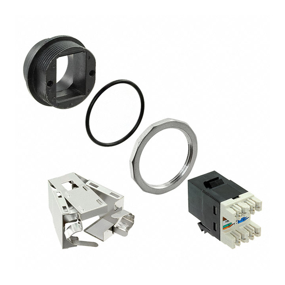
Each kit consists of a receptacle and either an in-line coupler or jack (with strain relief or dust cover). A nut and
O-ring is included for installing the receptacle in a panel or faceplate. The SL series jack kit includes a shield.
See Figure 1.
NOTE
Dimensions in this instruction sheet are in metric units [with U.S. customary units in brackets]. Figures are not drawn to scale.
Reasons for re-issue of this instruction sheet are provided in Section 2, REVISION SUMMARY.
1. ASSEMBLY
1.1. Wire Preparation and Jack Termination
Prepare the wire and terminate the jack according to the instruction sheet listed in Figure 1.
NOTE
The jacks accepts 4-pair, twisted-pair cable having sizes 24 to 22 AWG solid conductors. The SL series jack also accepts
cable having sizes 26 to 24 AWG stranded conductors with a maximum conductor insulation diameter of 1.27 mm [.050 in.].
1.2. Panel or Faceplate Cutout
Cut the panel or faceplate according to Figure 2.
To obtain information on CommScope
®
contact your local CommScope
account
™
representative, PartnerPRO
Network Partner
or visit our website at
www.commscope.com
ETHERSEAL
Dust Cover
Bend-Limiting
Strain Relief
SL Series Jack, Unshielded Twisted Pair Category 5e
SL Series Jack , Shielded Category 5e
SL Series Jack , Unshielded Twisted Pair Category 6
SL Series Jack , Shielded Category 6
In-Line Coupler , Unshielded Twisted Pair Category 5e
In-Line Coupler , Shielded Category 5e
AMP-TWIST 6S Jack
®
products,
©2016 CommScope, Inc.
All Rights Reserved
Receptacle Kits
®
AMP-TWIST
6S Jack
SL Series
Jack
DESCRIPTION
Figure 1
Instruction Sheet
408-8875
DEC. 2016
Receptacle
O-Ring
Nut
INSTRUCTION SHEET
408-8417
408-8602
408-8417
408-8417
NA
NA
411-93007
This product is covered by one or more U.S.patents
or their foreign equivalents. For patents, see
www.commscope.com /ProductPatent/ProductPatent.aspx
Rev E
1 of 2
Advertisement

Related Manuals for CommScope ETHERSEAL 1479563-2


Summary of Contents for CommScope ETHERSEAL 1479563-2
- Page 1 26 to 24 AWG stranded conductors with a maximum conductor insulation diameter of 1.27 mm [.050 in.]. 1.2. Panel or Faceplate Cutout Cut the panel or faceplate according to Figure 2. ® 1 of 2 To obtain information on CommScope products, ©2016 CommScope, Inc. This product is covered by one or more U.S.patents ®...
- Page 2 Rotate Fixed Latch Jack Fixed Latch Jack (Ref) Slot Inside of Opening of Movable Latch Receptacle Receptacle Movable Latch Figure 3 2. REVISION SUMMARY Revisions to this instruction sheet include: ® Rebranded to CommScope 2 of 2 Rev E...