
Related Manuals for EKKO ES40E


Summary of Contents for EKKO ES40E
- Page 1 Electric Scissor Lift Work Platform Operator’s and Service Manual Applies to ES40E/ES60E/ES80E/ES100E/ES120E Frist Edition January 2022...
-
Page 2: Table Of Contents
Owners Users and Operators: Thank you for choosing our company and use Attention our machines. Our number one priority is user safety, which is best achieved by our joint You should read, understand and follow these efforts. We think that as a user and operator, if safety rules and operating instructions before you can comply with the following requirements, operating this machine. -
Page 3: Safety Rules
Safety Rules √ You are properly trained to safely operate the machine. Hazard Classification products use symbols, color coding and Danger signal words to identify the following: Failure to obey the instructions Safety alert symbol—used to alert and safety rules in this manual you to potential personal injury hazards. -
Page 4: Decals
A11000076 Batteries Safety Decals and Location A11000024 Use Safety Arm A11000026 Batteries/Charger Safety Decals inspection of Model ES40E A11000018 Power to Charger Ensure that there are decals with words or Electrocution Hazard, A11000030 symbols on the machine. Using appropriate test... - Page 5 Decals...
- Page 6 Decals Safety Decals and Location Tip-over Hazard, Open A11000027 Trays Tip-over Hazard, Decals inspection of Model A11000076 Batteries, ES07 ES60E A11000024 Use Safety Arm A11000026 Batteries/Charger Safety Ensure that there are decals with words or symbols on the machine. Using appropriate test A11000018 Power to Charger methods to check that if all labels are easy to...
- Page 7 Decals...
- Page 8 Decals Safety Decals and Location A11000152 Wheel Load,ES80E A11000148 Wheel Load,ES100E Decals inspection of Model ES80E/ES100E/ES120E A11000149 Wheel Load,ES120E Ensure that there are decals with words or A11000145 Crushing Hazard symbols on the machine. Using appropriate test methods to check that if all labels are easy to A11000146 Crushing Hazard recognize and have a appropriate location.
- Page 9 Decals...
-
Page 10: Personal Safety
Personal Safety Work Area Safety Personal Fall Protection Electrocution Hazards This machine is not electrically insulated and Personal fall protection equipment (PFPE) is will not provide protection from contact with or not required when operating this machine. If proximity to electrical current. PFPE is required by job site or employer rules, the following shall apply: All PFPE must comply with applicable... - Page 11 Maximum Model retracted only occupants indicator. The tilt alarm sounds on the chassis only when the machine is on a severe slope. 500 lbs ES40E 220 lbs Indoor If the tilt alarm sounds: Indoor 500 lbs 260 lbs ES60E Lower the platform. Move the machine to a Outdoor firm, level surface.
- Page 12 Platform Model Extension only retracted Do not transport tools and materials unless they are evenly distributed and can be safely ES40E 400N Only indoor-2P handled by person(s) in the platform. 400N Indoor-2P Do not use the machine on a moving or mobile...
- Page 13 Maximum Maximum slope side slope Model Collision Hazards rating, rating, stowed stowed position position ES40E 25%(14°) 25%(14°) ES60E 25%(14°) 25%(14°) ES80E 30% (17°) 30%(17°) Be aware of limited sight distance and blind ES100E 25% (14°) 25% (14°) spots when driving or operating.
- Page 14 Work Area Safety Damaged Machine Hazards Do not use a damaged or malfunctioning machine. Conduct a thorough pre-operation inspection of the machine and test all functions before each work shift. Immediately tag and remove from service a damaged or malfunctioning machine. Be aware of crushing hazards when grasping the platform guard rail.
- Page 15 Keep sparks, flames and lighted tobacco away Model Weight of tray from batteries. Batteries ES40E 170 lbs emit explosive gas. The battery tray should 340 lbs ES60 remain open during the ES80 entire charging cycle.
-
Page 16: Legend
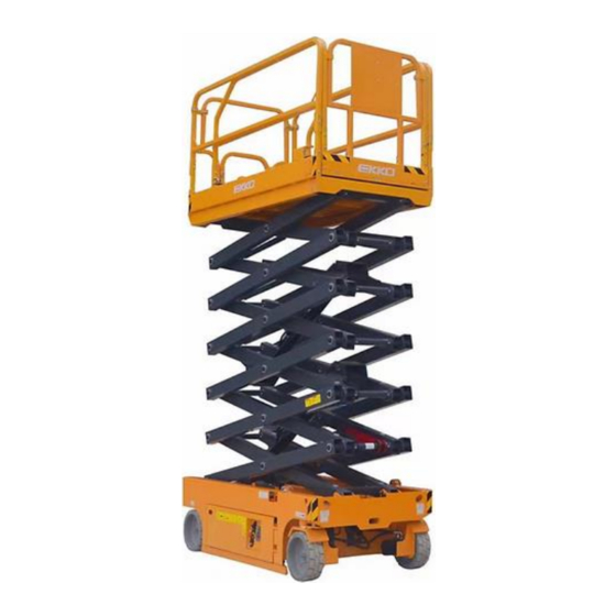
Legend ES40E Platform guard rails Lanyard anchorage points Manual storage container Platform controls Platform extension Platform-socket and air pipes(optional) Scissor arm Transport tie-down Steering wheel 10 Pothole guard 11 Ground controls 12 Timer 13 Non-steering wheel 14 Brake release pump... - Page 17 Legend ES60E Platform guard rails Lanyard anchorage points Manual storage container Platform controls Platform extension Platform-socket and air pipes(optional) Scissor arm Transport tie-down Steering wheel 10 Pothole guard 11 Ground controls 12 Timer 13 Non-steering wheel 14 Brake release pump 15 Entry ladder 16 Emergency lowering line 17 Lift cylinder...
- Page 18 Legend Platform guard rails Lanyard anchorage points Manual storage container ES80E/ES100E/ES120E Platform controls Platform extension Platform-socket and air pipes(optional) Scissor arm Transport tie-down Steering wheel 10 Pothole guard 11 Timer 12 Ground controls 13 Non-steering wheel 14 Brake release pump 15 Entry ladder 16 Emergency lowering line 17 Lift cylinder...
-
Page 19: Controls
Controls A11000019 A11000019 Ground Control Panel 1 Key switch for platform/off/ground selection 10 Lifting key Turn the key switch to the platform position and Press and hold the lifting key and the platform the platform controls will operate. Turn the key rising key at the same time can operate the switch to the off position and the machine will be ascending function. - Page 20 Controls Platform Control panel Platform control panel 1 Thumb rocker switch for steer function 5 Horn button 2 Drive function button 6 Lift function button 3 Drive speed select button 7 LED 4 Red Emergency Stop button 8 Proportional control handle and function enable switch for drive and lift functions...
- Page 21 Controls handle in the direction indicated by the blue Platform control panel arrow on the control panel and the machine 1 Thumb rocker switch for steer function will move in the direction that the blue arrow Press both of the thumb rocker and the points.
-
Page 22: Pre-Operation Inspection
Pre-operation Inspection Pre-operation Inspection Fundamentals It is the responsibility of the operator to perform a pre-operation inspection and routine maintenance. Do Not Operate Unless: The pre-operation inspection is a visual √ You learn and practice the principles of inspection performed by the operator prior to safe machine operation contained in this each work shift. -
Page 23: Function Test
Function Test Check entire machine for: Pre-operation Inspection ● Cracks in welds or structural components ● Be sure that the operator’s, safety and ● Dents or damage to machine responsibilities manuals are complete, legible and in the storage container located in the ●... - Page 24 Function Test Test Emergency Stop 6.Push in the ground red Emergency Stop button to the off position. ⊙ Result: No functions should operate. 7.Pull out the red Emergency Stop button to the on position. Do Not Operate Unless: Test the Up/Down Functions √...
- Page 25 Function Test Note: When performing the steer and drive Emergency stop function tests, stand in the platform facing the 16.Push in the platform red Emergency Stop steer end of the machine. button to the “off” position. 26.Press the drive function button. ⊙...
- Page 26 Function Test Test elevated drive speed Test the pothole guards 34.Press the lift function. Press and hold the ote: The pothole guards should function enable switch on the control automatically deploy when the platform handle. Raise the platform approximately is raised. The pothole guards activate 2.1 m from the ground.
-
Page 27: Workplace Inspection
Workplace Inspection Fundamentals The workplace inspection helps the operator determine if the workplace is suitable for safe machine operation. It should be performed by the operator prior to moving the machine to the workplace. Do not operate, unless: It is the operator’s responsibility to read and √... -
Page 28: Operating Instructions
Operating Instructions Repair any function that operates when either red Emergency Stop button is pushed in. Emergency Lowering 1. Pull the emergency lowering knob to lower the platform. Do Not Operate Unless: Operation from Ground √ You learn and practice the principles of safe Be sure the battery pack is connected machine operation contained in this operator’s before operating the machine. - Page 29 Operating Instructions To drive Press the drive function button. ES40E,60E,ES80E,ES100E,ES120E Press and hold the function enable switch Max. slope rating, stowed position: on the control handle. Max. side slope rating, stowed position: 25% Increase speed: Slowly move the control handle off center.
- Page 30 Operating Instructions Replace the two removed pins back into each side of bracket. Operational Indicator Codes At the rear of the main deck, remove the two main deck lock pins。 Operator, machine and fixed objects should keep a safe distance. Pay attention to the Fold down the rear gate and entry side direction when using the controller.
- Page 31 Operating Instructions General Brake Coil Fault Operational indicator codes Low Voltage Fault If the platform controls LED Over 80% Load Warning indicator code (such as LL ) ,Push in and pull out the red Over 90% Load Warning Emergency Stop button to reset Over 99% Load Warning the system Overloaded Platform Fault...
- Page 32 Operating Instructions Check the battery acid level when the charging cycle is complete. Replenish with distilled water to the bottom of the fill tube. Do not overfill. Dry Battery Filling and Charging Instructions Battery and Charger Remove the battery vent caps and permanently remove the plastic seal from Instruction the battery vent openings.
-
Page 33: Transporting And Lifting Instructions
Transporting And Lifting Instructions Brake release operation For hydraulic drive products of ES40E,60, Observe and obey: ES80E, ES100E, ES120E. √ While using a crane lifting machine, keep Chock the wheels to prevent the machine the normal judgment and planned to from rolling. - Page 34 Transporting And Lifting Instructions Securing to truck or trailer for transit Always use the extension deck lock when the machine is transported. Observe and obey: Fixed on the chassis in the transport plane √ Only qualified forklift operators should lift the through fastening parts of machine.
- Page 35 Adjust the rigging to prevent damage to the ES80E,ES100E,ES120E machine and to keep the machine level. core X SHAFT YSHAFT ES40E 19.64 Inch 18.93 Inch ES60E 25.35 Inch 20.75 Inch ES80E 33.66 Inch 23.54 Inch...
-
Page 36: Specifications
Specifications ES40E Height, working maximum 244 Inch Maximum hydraulic 240Bar Height, platform maximum 165 Inch pressure (functions) Φ230×80 Height, stowed maximum Tire size 80.7 Inch Railing raised Sound pressure <70 dB Height, stowed maximum level 67.0 Inch Railing lowered The maximum noise level normally (A level Width with standard wheels 30.0 Inch... - Page 37 Specifications ES60E Height, working maximum 307 Inch Maximum hydraulic 240Bar Height, platform maximum 228.3 Inch pressure (functions) Height, stowed maximum Φ323×100 Tire size 85.4 Inch Railing raised Sound pressure level <70 dB Height, stowed maximum 72.4 Inch Railing lowered The maximum noise level normally (A level detection) Width with standard wheels 31.9 Inch...
- Page 38 Specifications ES80E Maximum hydraulic Height, working maximum 393.7 Inch 240Bar pressure (functions) Height, platform maximum 315 Inch Φ381×129 Tire size Height, stowed maximum 94.5 Inch Sound pressure level <70 dB Railing raised The maximum noise level normally (A level Height, stowed maximum 67.3 Inch detection) Railing lowered...
- Page 39 Specifications ES100E Height, working maximum 472.4 Inch Height, platform maximum 393.7 Inch Maximum hydraulic 240Bar pressure (functions) Height, stowed maximum 96.8 Inch Φ381×129 Railing raised Tire size Height, stowed maximum Sound pressure level <70 dB 72.4 Inch Railing lowered The maximum noise level normally (A level Width with standard wheels 45.3 Inch detection)
- Page 40 Specifications ES120E Height, working maximum 547.2 Inch Maximum hydraulic 240Bar Height, platform maximum 468.5 Inch pressure (functions) Height, stowed maximum Φ381×129 Tire size 102.3 Inch Railing raised Sound pressure level <70 dB Height, stowed maximum 77.9 Inch Railing lowered The maximum noise level normally (A level detection) Width with standard wheels 43.7 Inch...
-
Page 41: Maintenance
Maintenance Inspect the Batteries Proper battery condition is essential to good Observe and Obey: machine performance and operational safety. Improper fluid levels or damaged cables and √ Only routine maintenance items specified connections can result in component damage in this manual shall be performed by the and hazardous conditions. - Page 42 Maintenance Pre-delivery Preparation Report Check the Hydraulic Oil Level The pre-delivery preparation report contains checklists for each type of scheduled inspection. Maintaining the hydraulic oil at the proper level Make copies for each inspection. Store is essential to machine operation. Improper completed forms as required.
- Page 43 Maintenance Fundamentals Instructions It is the responsibility of the dealer to perform Use the operator’s manual on your machine. the Pre-delivery Preparation. The Pre-delivery Preparation consists of The Pre-delivery Preparation is performed completing the Pre-operation Inspection, the prior to each delivery. The inspection is Maintenance items and the Function Tests.
- Page 44 Maintenance Maintenance Inspection Report Model Checklist A. Y N R Serial number A-1 Inspect the manuals and decals Date A-2 Pre-operation inspection A-3 Function tests Hour meter After 40 hours: Machine owner A-4 30-day service Inspected by (print) After 100hours: Inspector signature A-5 Grease steer yokes Inspector title...
- Page 45 Maintenance Checklist A Always return the manuals to the storage container after use. Inspect the Manuals and Decals Note: Contact your authorized distributor or if replacement manuals or decals are needed. Maintaining the operator’s and safety manuals in good condition is essential to safe machine operation.
- Page 46 Maintenance •D-2 Replace the Hydraulic Tank Return Filter Element. Checklist B Grease the Steer Yokes Inspect the Batteries This procedure be performed every 250 hours This procedure be performed every 100 hours or quarterly, whichever comes first. of operation. Proper battery condition is essential to good machine performance and operational safety.
- Page 47 Maintenance • Add 0.004 to the reading of each cell for every 10° / 5.5° C above 80° F / 26.7° C. • Subtract 0.004 from the reading of each cell for every 10° / 5.5° C below 80° F / 26.7° C. ⊙Result: All battery cells display an adjusted specific gravity of 1.277 or higher.
- Page 48 Maintenance Electrocution/explosion hazard. Inspect the Tires and Wheels Contact with electrically charged circuits could result in death or serious injury. Remove all rings, watches and other jewelry. This procedure should be performed every Inspect the underside of the chassis for 250 hours or quarterly, whichever comes first.
- Page 49 Maintenance ⊙ Result: No machine functions should The horn is activated at the platform controls and sounds at the ground as a warning to operate. ground personal. An improperly functioning 3. Turn the key switch to platform control horn will prevent the operator from alerting and pull out the red Emergency Stop ground personal of hazards or unsafe button to the on position at both the...
- Page 50 Maintenance Choose a point on the machine; i.e., the on position at both the ground and contact patch of a tire, as a visual platform controls. reference for use when crossing the test 3. Lower the platform to the stowed position. line.
- Page 51 Maintenance the on position at both the ground and platform controls. 3. Lower the platform to the stowed position. 4. Press the drive speed select button a. Platform up button b. Drive function select button 4. Press function button a. drive speed select button 5.
- Page 52 Maintenance 2. Lubricate each module tray rotary latch. Inspect the Hydraulic Tank Cap Using light oil, apply a few drops to each Venting System of the springs and to the sides of the rotary latch mechanism. B-14 This procedure should be performed every Test the Down Limit Switch, Level 250 hours or quarterly, whichever comes first.
- Page 53 Maintenance 12. Working at the platform controls, press 20. Disconnect the platform controls from the the lift function select button. Lower the ECU cable. platform to the stowed position. 21. Securely install the connector of the ECU ⊙ Result: The diagnostic LCD displays "18", cable into the platform control cable.
- Page 54 Maintenance sounds and the platform will lift to 2m or 1. Turn the key switch to ground control and beyond. The machine is function properly. raise the platform approximately 2.5 m ¤ Result: The pothole guard contacts the from the ground. block and does not fully deploy.
- Page 55 Maintenance sensor, then stop the machine until the excess 8. Raise the platform to the highest position load is removed from the platform. and continue to press the up function select button. ⊙ Result: The motor does not operate. The machine is functioning properly.
- Page 56 Maintenance This procedure should be performed every the non-steer end of the machine. 500 hours or six months, whichever comes first. The hydraulic tank is a vented-type tank. The breather cap has an internal air filter that can become clogged or, over time, can deteriorate. If the breather cap is faulty or improperly installed, impurities can enter the hydraulic system which may cause component damage.
- Page 57 Maintenance Beware of hot oil Contact with hot oil may Before replacing the hydraulic oil, the oil may cause severe burns. be tested by an oil distributor for specific levels of contamination to verify that changing the oil The hydraulic tank return filter is necessary.
- Page 58 Maintenance Non-lubrication drain plug 4.5 Nm Lubrication drain plug 3.4 Nm 11. Put back the tank, install and tighten the hydraulic oil tank of the fasteners. Torque according to the following requirement: Torque to specification. Non-lubrication hydraulic tank 4.0 Nm fastener Lubrication hydraulic tank fastener 2.9 Nm...
-
Page 59: Electrical Schematic Diagram
Electrical Schematic Diagram ES40E... - Page 60 Electrical Schematic Diagram ES60E,ES80E,ES100E,ES120E...
-
Page 61: Hydraulic Schematic Diagram
Hydraulic Schematic Diagram ES60E 28-35bar 28-35bar B1 B1 AS AS BS BS BR BR 207bar B1 B1 2.5L/Min 109bar 241bar B2 B2 T1 T1 11.2L/min 11.2L/min 10 10 μ m 2950rpm 2950rpm 1.5bar 1.5bar... - Page 62 Hydraulic Schematic Diagram ES80E G1/4-19 Y1 Y1...
- Page 63 Hydraulic Schematic Diagram ES100E/ES120E G1/4-19 Y1 Y1...
-
Page 64: Maintenance Record
Hydraulic Schematic Diagram Maintenance Record Date Note...
Need help?
Do you have a question about the ES40E and is the answer not in the manual?
Questions and answers