Table of Contents
Advertisement
Quick Links
Advertisement
Table of Contents

Related Manuals for Edimax ES-5240G+


Summary of Contents for Edimax ES-5240G+
- Page 1 ES-5240G+ 24-Port GbE Web Smart Switch User's Manual Version 1.0 / June 2007...
- Page 2 COPYRIGHT Copyright© 2007 Edimax. All rights reserved. No part of this publication may be reproduced, transmitted, transcribed, stored in a retrieval system, or translated into any language or computer language, in any form or by any means, electronic, mechanical, magnetic, optical, chemical, manual or otherwise, without the prior written permission of Edimax.
-
Page 3: Table Of Contents
2-1. Starting 24-Port GbE Web Smart Switch Up...7 2-1-1. Hardware and Cable Installation ...7 2-1-2. Cabling Requirements ...8 2-1-3. Configuring the Management Agent of 24-Port GbE Web Smart Switch ...13 2-1-4. IP Address Assignment...15 2-2. Typical Applications...20 Basic Concept and Management...22 3-1. - Page 4 4-3-5. IGMP Status...90 4-3-6. Ping Status...92 4-4. Maintenance...94 4-4-1. Warm Restart...95 4-4-2. Factory Default ...96 4-4-3. Software Upgrade...97 4-4-4. Configuration File Transfer ...98 4-4-5. Logout...99 5. Maintenace ...100 5-1. Resolving No Link Condition ...100 5-2. Q&A...100 Appendix A Technical Specifications...101 Appendix B MIB Specifications...105...
-
Page 5: Caution
Caution Circuit devices are sensitive to static electricity, which can damage their delicate electronics. Dry weather conditions or walking across a carpeted floor may cause you to acquire a static electrical charge. To protect your device, always: • Touch the metal chassis of your computer to ground the static electrical charge before you pick up the circuit device. -
Page 7: Introduction
In addition, the switch implements the QoS (Quality of Service), VLAN, and Trunking features. It is suitable and optimized for office applications. -
Page 8: Checklist
1-2. Checklist Before you start installing the switch, verify that the package contains the following: 24-Port GbE Web Smart Switch SFP Modules (optional) Mounting Accessory (for 19" Rack Shelf) CD-ROM with User's Manual Power Adapter Please notify your sales representative immediately if any of the aforementioned items is missing or damaged. - Page 9 • Supports to send the trap event while monitored events happened • Supports default configuration which can be restored to overwrite the current configuration which is working on via Web UI and Reset button of the switch • Supports hot swap plug/unplug SFP modules •...
-
Page 10: View Of 24-Port Gbe Web Smart Switch
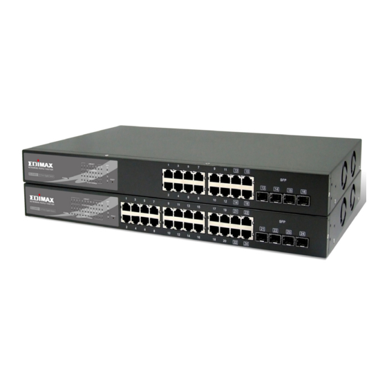
There are 24 TP Gigabit Ethernet ports and 4 SFP fiber ports for optional removable modules on the front panel of the switch. LED display area. Locating on the left side of the panel, Power LED, which indicates the power status and 24 ports working status of the switch. -
Page 11: User Interfaces On The Rear Panel
Lit when SFP connection with remote device is SFP(LINK/ACT) Green good Blinks when any traffic is present Table1-ES-5240G+ LED Indicators table 1-4-2. User Interfaces on the Rear Panel Fig. 1-3 Rear View of 24-PORT GBE WEB SMART SWITCH Function AC Line 100-240V 50/60 Hz... -
Page 12: View Of The Optional Modules
1-5. View of the Optional Modules Port 21~24 on this switch support two types of media --- TP and SFP Fiber (LC, BiDi-SC…); this port supports 10/100/1000Mbps TP or 1000Mbps SFP Fiber with auto-detected function. 1000Mbps SFP Fiber transceiver is used for high- speed connection expansion;... -
Page 13: Installation
At the beginning, please do first: Wear a grounding device to avoid the damage from electrostatic discharge. Be sure that power switch is OFF before you plug in AC power source Installing Optional SFP Fiber Transceivers to the 24-Port GbE Web Smart Switch Note: If you do not have modules, please skip this section. -
Page 14: Cabling Requirements
(Cable pin-outs for RJ-45 jack 1, 2, 3, 6 to 3, 6, 1, 2) can be used. ⇒ Use Cat. 5 grade RJ-45 TP cable to connect to a TP port of the switch. Connect the other end to a network-aware device, such as a workstation or a server. - Page 15 2-1-2-1. Cabling Requirements for TP Ports ⇒ For Fast Ethernet TP network connection ⎯ The grade of the cable must be Cat. 5 or Cat. 5e with a maximum length of 100 meters. ⇒ Gigabit Ethernet TP network connection ⎯ The grade of the cable must be Cat. 5 or Cat. 5e with a maximum length of 100 meters.
- Page 16 Level 1 switch and connect all other switches to it at Level 2. Server/Host is recommended to connect to the Level 1 switch. This is general if no VLAN or other special requirements are applied.
- Page 17 Case1: All switch ports are in the same local area network. Every port can access each other (See Fig. 2-2). Fig. 2-2 No VLAN Configuration Diagram If the VLAN is enabled and configured, each node in the network that can communicate each other directly is bounded to the same VLAN area.
- Page 18 Case 2b: Port-based VLAN (See Fig.2-4). Fig. 2-4 Port-based VLAN Diagram 1. VLAN1 members can not access VLAN2, VLAN3 and VLAN4 members. 2. VLAN2 members can not access VLAN1 and VLAN3 members, but they can access VLAN4 members. VLAN3 members can not access VLAN1, VLAN2 and VLAN4. 4.
-
Page 19: Configuring The Management Agent Of 24-Port Gbe Web Smart Switch
Users can monitor the status of the switch, as well as to configure the switch through this web- based interface. Here we will guide you through how to access this web based management interface. - Page 20 IP address for the switch and have the IP information ready. Then, follow the procedures listed below. 1. Set up a physical path between the configured switch and a PC with a qualified UTP Cat. 5 cable with RJ-45 connectors.
-
Page 21: Ip Address Assignment
Fig. 2-7 the Login Screen for Web 2-1-4. IP Address Assignment For IP address configuration, four parameters are required. They are IP address, Subnet Mask, Default Gateway and DNS. IP address: The IP address of the network device in a network is used for internetworking communication. - Page 22 According to IPv4, the IP addressed are divided three classes, class A, class B and class C. The rest of IP addresses are for multicast and broadcast. The bit length of the network prefix is the same as that of the subnet mask and is denoted as IP address/X, for example, 192.168.1.0/24.
- Page 23 Class D and E: Class D is a class with first 4 MSB (Most significance bit) set to 1-1-1-0 and is used for IP Multicast. See also RFC 1112. Class E is a class with first 4 MSB set to 1-1-1-1 and is used for IP broadcast. According to IANA (Internet Assigned Numbers Authority), there are three specific IP address blocks reserved and to be used for extending internal network.
- Page 24 In this diagram, you can see the subnet mask with 25-bit long, 255.255.255.128, contains 126 members in the sub-netted network. Another is that the length of network prefix equals the number of the bit with 1s in that subnet mask. With this, you can easily count the number of IP addresses matched.
- Page 25 IP address, which is known as the default router. This is a routing policy. For assigning an IP address to the switch, you need to check what the IP address of the network will be connected to the switch. Use the same network address and append your host address to it.
-
Page 26: Typical Applications
2-2. Typical Applications The 24-Port GbE Web Smart Switch implements 24 Gigabit Ethernet TP ports with auto MDIX and four slots for removable modules Comprehensive fiber types of connection including LC and BiDi-LC SFP modules are supported. For more detailed specifications of the switch, please refer to Appendix A. - Page 27 Fig. 2-11 Peer-to-peer Network Connection Fig. 2-12 Office Network Connection...
-
Page 28: Basic Concept And Management
Management In this chapter we are going to introduce you the basic concepts and features of Ethernet, and how to work with the management features provided by this switch. 3-1. What’s the Ethernet Ethernet originated and was implemented at Xerox in Palo Alto, CA in 1973 and was successfully commercialized by Digital Equipment Corporation (DEC), Intel and Xerox (DIX) in 1980. - Page 29 Data Link Layer IEEE802.3 CSMA/CD MAC IEEE 802.3 PLS Physical Layer IEEE 802.3 Coaxial/STP/UTP The above diagram shows the Ethernet architecture in OSI model. LLC sub- layer and MAC sub-layer will respond to the Data Link layer, and the transceivers will respond to the Physical layer.
- Page 30 The table 3-1 is the format of LLC PDU. It comprises four fields, DSAP, SSAP, Control and Information. The DSAP address field identifies the one or more service access points, in which the I/G bit indicates it is individual or group address. If all bits of DSAP are 1s, it’s a global address.
-
Page 31: Media Access Control (Mac)
3-2. Media Access Control (MAC) MAC Addressing Because LAN is composed of many nodes, for the data exchanged among these nodes, each node must have its own unique address to identify who should send the data or should receive the data. In OSI model, each layer provides its own mean to identify the unique address in some form, for example, IP address in network layer. - Page 32 Bit 47 1st byte 2nd byte 3rd byte OUI code Table 3-3 Ethernet MAC address The first bit of the first byte in the Destination address (DA) determines the address to be a Unicast (0) or Multicast frame (1), known as I/G bit indicating individual (0) or group (1).
- Page 33 Destination address (DA) — The DA field is used to identify which network device(s) should receive the packet. It is a unique address. Please see the section of MAC addressing. Source addresses (SA) — The SA field indicates the source node. The SA is always an individual address and the left-most bit in the SA field is always 0.
- Page 34 How does a MAC work? The MAC sub-layer has two primary jobs to do: 1. Receiving and transmitting data. When receiving data, it parses frame to detect error; when transmitting data, it performs frame assembly. 2. Performing Media access control. It prepares the initiation jobs for a frame transmission and makes recovery from transmission failure.
- Page 35 All chips, and as well as all network vendors' devices, support full- duplex mode only. It is safe to say that this criterion does not exist for both present time and in the future. The switch’s Gigabit module supports only full-duplex mode. 64 bytes...
- Page 36 Parameter 10Base value/LAN Max. collision domain DTE to 100 meters Max. collision domain with 2500 meters repeater Slot time 512 bit times Interframe Gap 9.6us AttemptLimit BackoffLimit JamSize 32 bits MaxFrameSize 1518 MinFrameSize BurstLimit Not applicable Table 3-4 Ethernet parameters for half duplex mode In full-duplex operation mode, both transmitting and receiving frames are processed simultaneously.
-
Page 37: Flow Control
PAUSE operation can not be used to inhibit the transmission of MAC control frame. Normally, in 10Mbps and 100Mbps Ethernet, only symmetric flow control is supported. However, some switches (e.g. 24-Port GbE Web Smart Switch) support not only symmetric but also asymmetric flow controls for special applications. In Gigabit Ethernet, both symmetric flow control and asymmetric flow control are supported. - Page 38 Frame Reception In essence, the frame reception is the same in both operations of half duplex and full duplex, except that full-duplex operation uses two buffers to transmit and receive the frame independently. The receiving node always “listens” if there is traffic running over the medium when it is not receiving a frame.
- Page 39 0x8100 at the location of the Length/Type field of the normal non-VLAN frame, it will interpret the received frame as a tagged VLAN frame. If this happens in a switch, the MAC will forward it, according to its priority and egress rule, to all the ports that is associated with that VID.
-
Page 40: How Does A Switch Work
Micro-segmentation: To have a port of the switch connected to a single host is referred to as micro-segmentation. It has the following interesting characteristics. Access contention (e.g. Collision) is not necessary. Each micro-segment has its own access domain;... - Page 41 2500 meters and 185 meters when using coaxial cable. The switch with its per port per collision domain can extend the distance like a bridge does. And what’s more, when operating in full-duplex mode, the distance can reach farther than half duplex because it is not limited by the maximum propagation delay time (512 bits time).
- Page 42 (DA) to find 1) if SA exists in the MAC address table, if it does not, the switch will put it in the MAC address table; if it does, 2) the switch looks up DA and its associated port to which the traffic is forwarded. If DA does not exist, the switch will broadcast the packet.
- Page 43 There is a field in MAC address table used to put the entry’s Age time which determines how long a MAC entry can reside in a switch. The age time is refreshed when a packet with that SA arrives. Usually, the age time is programmable.
-
Page 44: Virtual Lan
3-5. Virtual LAN What is a VLAN? It is a subset of a LAN. Before we discuss VLAN, we must understand what LAN is. In general, a LAN is composed of different physical network segments bridged by switches or bridges which attach to end stations in the same broadcast domain. - Page 45 Now we apply VLAN technology to configure the system shown as the figure above. We can partition the users into the different logical networks which have their own broadcast domain. The traffic will not disturb among these logical networks. The users 1x (x denotes a ~ d) are members of VLAN 1. Any traffic within VLAN 1 does not flow to VLAN 2 and others.
- Page 46 There are many types of VLAN applied. The most popular ones are port- based VLAN, tag-based VLAN and protocol-based VLAN. Port-based VLAN Some physical ports are configured as members of a VLAN. All stations attached on these ports can communicate with each other. Tag-based VLAN It identifies the membership by VLAN ID, no matter where the packet comes from.
- Page 47 VLAN-tagged frame: An Ethernet frame, carrying VLAN tag field, contains VLAN identification without the value of 0 and 4095, and priority information. Priority-tagged frame: An Ethernet frame, carrying VLAN tag field, contains VLAN identification with the value of 0 and priority information. Untagged frame: An Ethernet frame carries no VLAN tag information.
- Page 48 VLAN to learn or look up the membership information of the VLAN. In 24-Port GbE Web Smart Switch, you can choose a VID for sharing filtering database in Shared VID field if you wish to use the existed filtering database.
- Page 49 VLAN covers. If we plan to deploy four VLANs in an office and use a switch to partition them, we need to check the ports/VLAN assignment first. Assuming a 24-port switch is applied.
-
Page 50: Link Aggregation
Therefore, offering a tool with automatic recovery capability is necessary for an administrator. LACP is a protocol that allows a switch to be able to know whether its partner has the capability to co-setup a trunk between them. - Page 51 There are three cases of link used in the network, which are switch to switch, switch to station and station to station. Here a station may be a host or a router. Link Aggregation, called port trunking sometimes, has two types of link configuration, including static port trunk and dynamic port trunk.
-
Page 52: Operation Of Web-Based Management
TP media. With this facility, you can easily access and monitor the statuses of all ports through any one port of the switch, including MIBs status, activity of each port, multicast traffic, and so on. -
Page 53: Web Management Home Overview
4-1. Web Management Home Overview After you login, the switch shows you the system status information as Fig. 4- 2. This is the default page and it displays you with the basic information of the system, including “Switch Status”, “TP Port Status”, “Fiber Port Status”, “Aggregation”, “VLAN”, “Mirror”, “SNMP”, and “Maximum Packet Length”. - Page 54 The Information of Page Layout • On the top, it shows the front panel of the switch. In the front panel, green LEDs ⎯ on to show linked ports in function; optional modules, the slot will show only a cover plate if no module other hand, it will show a module if one presents.
-
Page 55: Configuration
4-2. Configuration Fifteen functions, including System Configuration, Ports Configuration, VLAN Mode Configuration, VLAN Group Configuration, IGMP Snooping, Mirror, QoS, Filter, Rate Limit, Storm Control and SNMP this function folder for system and network management. Each of them will be described in detail orderly in the following sections. Configuration Aggregation LACP, RSTP, 802.1X,... -
Page 56: System Configuration
4-2-1. System Configuration System configuration is one of the most important configurations in the switch. Without proper settings, network administrator will not be able to manage or view the status of this device.The switch supports manual IP address Function name:... - Page 57 Lease Time Left: Show the lease time left of DHCP client. Device Name: Set a special name for this switch. Up to 16 characters are allowed in this parameter. Any alphanumeric character and null are acceptable. Default: Giga Switch DHCP Enabled: Enable DHCP snooping, Just tick the check box ( ) to enable it.
- Page 58 Default: 192.168.1.254 Management VLAN: Show the management VLAN number. Password: Set a password for this switch. Up to 16 characters are allowed in this parameter. Any alphanumeric character is acceptable. Default: admin Inactivity Timeout(secs): Set the auto-logout timer. The valid value is 0 ~ 60 in the unit of minute and a decimal point is not allowed.
-
Page 59: Ports Configuration
4-2-2. Port Configuration Function name: Ports Configuration Function description: Ports Configuration is applied to change the settings of each port. In this configuration function, you can set/reset the following parameters, Mode and Flow Control. All of them are described in details below. Parameter description: Enable Jumbo Frames: This function supports jumbo frames of up to 9600 bytes, Just tick the... -
Page 60: Vlan Mode Configuration
1, you can communicate with port 2&3&4. If you are on the port 5, then you cannot talk to them. Each port-based VLAN you built up must be assigned a group name. This switch can support up to maximal 24 port-based VLAN groups. - Page 61 The switch supports supplement of 802.1q. For more details, please see the section VLAN in Chapter 3.
-
Page 62: Vlan Group Configuration
ID, VID, Member of the existed tag-based VLAN group. The switch can store the configuration of port-based VLAN and tag-based VLAN separately. When you choose one of VLAN mode, the switch will bring you the responded VLAN configuration which keeps the default data. You can easily create or delete a VLAN group by pressing <Add>... - Page 63 Add Group: Create a new port-based VLAN or tag-based VLAN, which depends on the VLAN mode you choose in VLAN mode function. Fig. 4-8 Add or Remove VLAN Member Delete Group: Just tick the check box ( button to delete the group. Fig.
-
Page 64: Aggregation
4-2-5. Aggregation The Aggregation (Port Trunking) Configuration is used to configure the settings of Link Aggregation. You can bundle more than one port with the same speed, full duplex and the same MAC to be one single logical port, thus the logical port aggregates the bandwidth of these bundled ports This means you can apply your current Ethernet equipments to build the bandwidth aggregation. -
Page 65: Lacp
4-2-6. LACP The switch supports the link aggregation IEEE802.3ad standard. This standard describes the Link Aggregate Control Protocol (LACP), which is a protocol that dynamically creates and manages trunk groups. When you enable LACP link aggregation on a port, the port can automatically negotiate with ports at the remote end of a link to establish trunk groups. -
Page 66: Rstp
4-2-7. RSTP RSTP detects and breaks network loops and provides backup links between switches, bridges or routers. It allows a switch to interact with other RSTP – compliant switches in your network to ensure that only one path exists between any two stations on the network. - Page 67 RSTP Port Configuration Function description: Enable or disable RSTP protocol on the port which being selected and set path cost. Parameter description: Protocol Enabled: Just tick the check box ( then press the <Apply> button to apply. Edge: Just tick the check box ( Path Cost: Path cost is the cost of transmitting a frame on to a LAN through that port.
- Page 68 4-2-8. 802.1X 802.1x port-based network access control provides a method to restrict users to access network resources via authenticating user’s information. This restricts users from gaining access to the network resources through a 802.1x-enabled port without authentication. If a user wishes to touch the network through a port under 802.1x control, he (she) must firstly input his (her) account name for authentication and waits for gaining authorization before sending or receiving any packets from a 802.1x-enabled port.
- Page 69 PC A, then, is allowed to access B and C via the switch. If there are two switches directly connected together instead of single one, for the link connecting two switches, it may have to act two port roles at the end of the link: authenticator and supplicant, because the traffic is bi-directional.
- Page 70 On the initial stage, the supplicant A is unauthenticated and a port on switch acting as an authenticator is in unauthorized state. So the access is blocked in this stage. Initiating a session. Either authenticator or supplicant can initiate the message exchange. If supplicant initiates the process, it sends EAPOL-start packet to the authenticator PAE and authenticator will immediately respond EAP-Request/Identity packet.
- Page 71 Authentication server, the port you are using is set to be unauthorized.. The 802.1X “Enabled” is the type of authentication supported in the switch. In this mode, for the devices connected to this port, once a supplicant is authorized, the devices connected to this port can access the network resource through this port.
- Page 72 Mode: Enable or disable 802.1X function. RADIUS IP: RADIUS server IP address for authentication. Default: 0.0.0.0 RADIUS UDP Port: The port number to be used communicate with RADIUS server for the authentication service. The valid value ranges 1-65535. Default port number is 1812. RADIUS Secret: The secret key between authentication server and authenticator.
- Page 73 Force Reinitialize: Force the subscriber to reinitialize connection to the port. Force Reinitialize All: Force Reinitialize for all ports at once. ---------------- continue ----------------- Fig. 4-16 802.1X Configuration Statistics: Choose the port which you want to show of 802.1X statistics, the screen include Authenticator counters, backend Authenticator counters, dot1x MIB counters and Other statistics.
- Page 74 Fig. 4-17 802.1X Statistics Function name: 802.1x Parameters Function description: In here, user can enable or disable Reauthentication function and specify how often a client has to re-enter his or her username and password to stay connected to the port. Parameter description: Reauthentication Enabled: Choose whether regular authentication will take place in this port.
-
Page 75: Igmp Snooping
IGMP snooping enable group multicast traffic to only be forwarded to ports that are members of that group; thus allowing you to significantly reduce multicast traffic passing through the switch. All the functions should press <Apply> button to start up after you tick the check box. -
Page 76: Mirror Configuration
Mirror Configuration Function description: Mirror Configuration is to monitor the traffic of the network, this switch supports one port mirror multi ports. For example, we assume that Port A and Port B are Source Ports and Port C is Mirror Port respectively. The traffic passed by Port A and Port B will be copied to Port C for monitoring. -
Page 77: Qos(Quality Of Service) Configuration
4-2-11. QoS(Quality of Service) Configuration offers powerful QoS function. This function supports VLAN-tagged switch priority that can make precedence of 8 priorities, and DSCP(Differentiated Services Code Point) on Layer 3 of network framework. Fig. 4-21 QoS Configuration... - Page 78 Function description: This function will affect the priority of VLAN tag. Based on priority of VLAN tag, it can arrange 0~7 priorities, Priorities can map up to 4 queues of the switch (low, normal, medium, high) and possess different bandwidth distribution according to your weight setting.
- Page 79 DSCP can form total 64 (0~63) kinds of Traffic Class based on the arrangement of 6-bit field in DSCP of the IP packet. In the switch, the user is allowed to set up these 64 kinds of Classes that belong to any level of queue (low, normal, medium, high).
-
Page 80: Filter
There are three types of modes in this drop-down menu. Default is disabled. Disabled: Allow users from all IP address to log in to this switch and manage Static: Only the user from the IP Address set by administrator is allowed to login to this switch and manage it.. - Page 81 Fig. 4-24 Filter Configuration...
-
Page 82: Rate Limit
4-2-13 Rate Limit Function name: Ingress and Egress Bandwidth Setting Function description: Ingress and Egress Bandwidth Setting function is used to set up the limit of Ingress or Egress bandwidth for each port. Parameter description: Ingress: Set up the limit of Ingress bandwidth for the port you choose. Incoming traffic will be discarded if the rate exceeds the value you set up in Data Rate field. -
Page 83: Storm Control
Function description: Storm Control is used to block unnecessary frames of the multicast and broadcast that would have reduced the switch’s performance. When the frames of multicast or broadcast are over the rate and Strom Control is enabled, the frames that exceed the determined rate can be dropped. - Page 84 Parameter description: ICMP Rate: To enable the ICMP Storm capability. The user can use drop-down menu to select number of frames. Default is No Limit. The setting range is 1k~1024k per second. Learn Frames Rate: To enable the Learn Frames Storm capability. The user can use drop- down menu to select number of frames.
-
Page 85: Snmp
Basically, it is passive except issuing the trap information. The switch supports a switch to turn on or off the SNMP agent. If you set the field SNMP “Enable”, the SNMP agent will be started up. All supported MIB OIDs, including RMON MIB, can be accessed via the SNMP manager. - Page 86 Default SNMP function: Disable Default community name for Get: public Default community name for Set: private Default community name for Trap: public Fig. 4-27 SNMP Configuration...
-
Page 87: Monitoring
4-3. Monitoring There are six functions under in the monitoring function. Monitoring Statistics Overview Detailed Statistics LACP Status RSTP Status IGMP Status Ping... -
Page 88: Statistics Overview
4-3-1. Statistics Overview The function of Statistics Overview collects any information and provides the counting summary about the traffic of the port, no matter the packet is good or bad. In the Fig. 4-25, the window can show all ports’ counter information at the same time. -
Page 89: Detailed Statistics
4-3-2. Detailed Statistics Function name: Detailed Statistics Function description: Display the detailed counting number of each port’s traffic. In the Fig. 4-26, the window can show all counter information each port at one time. Parameter description: Rx Packets: The counting number of the packet received. RX Octets: Total received bytes. - Page 90 Tx Broad- and Multicast: Show the counting number of the transmitted broadcast with multicast packet. Tx Error Packets: Show the counting number of the received error packets. Rx 64 Bytes: Number of 64-byte frames in good and bad packets received.
- Page 91 Rx 65-127 Bytes: Number of 65 ~ 126-byte frames in good and bad packets received. Rx 128-255 Bytes: Number of 127 ~ 255-byte frames in good and bad packets received. Rx 256-511 Bytes: Number of 256 ~ 511-byte frames in good and bad packets received. Rx 512-1023 Bytes: Number of 512 ~ 1023-byte frames in good and bad packets received.
- Page 92 Tx Collisions: Number of collisions transmitting frames experienced. Tx Drops: Number of frames dropped due to excessive collision, late collision, or frame aging. Tx Overflow: Number of frames dropped due to the lack of transmitting buffer. Fig. 4-29 Detailed Statistics for each port...
-
Page 93: Lacp Status
4-3-3. LACP Status Function name: LACP Status Function description: Display the LACP status. In the Fig. 4-30, the window can show LACP information and status for each port at one time. Parameter description: LACP Aggregation Overview: Show the group/port status. Red signs are set by default for link down ports;... -
Page 94: Rstp Status
Show the root bridge’s forward delay time. Topology: Show the root bridge’s spanning tree topology. Root Id: Show root bridge ID of this network segment. If this switch is a root bridge, the “This switch is Root” will show this switch’s bridge ID. - Page 95 Fig. 4-31 RSTP Status...
-
Page 96: Igmp Status
4-3-5. IGMP Status Function name: IGMP Status Function description: Display the IGMP status. In the Fig. 4-29, the window can show VLAN ID for each multicast group. Parameter description: VLAN Id: Show VLAN Id for each multicast group. Querier: Show the group membership queries status. Queries transmitted: To count the group membership queries transmitted. - Page 97 Fig. 4-32 IGMP Status...
-
Page 98: Ping Status
4-3-6. Ping Status Function name: Ping Status Function description: To setting up the target IP address for ping function of ICMP protocol and display the pinging status. In the Fig. 4-30, the window can show the pinging information. Parameter description: Ping Parameters: Target IP address: Set up a Target IP address to ping. - Page 99 Fig. 4-33 Ping...
-
Page 100: Maintenance
4-4. Maintenance There are five functions under the maintenance section. Maintenance Warm Restart Factory Default Software Upgrade Configuration File Transfer Logout... -
Page 101: Warm Restart
Reboot the switch. Reboot takes the same effect as the RESET button on the front panel of the switch. Press <Yes> button to confirm a warm restart, and it will take around thirty (30) seconds to complete the system boot. -
Page 102: Factory Default
4-4-2. Factory Default Function name: Factory Default Function description: Factory Default provides the function to retrieve default settings and replace current configuration. Except the IP address setting, all settings will be restored to the factory default values when “Factory Default” function is performed. -
Page 103: Software Upgrade
4-4-3. Software Upgrade Function name: Software Upgrade Function description: Browse through your PC for a newer version of software pre-saved on your PC and upgrade the switch. Fig. 4-36 Software Upgrade... -
Page 104: Configuration File Transfer
If a device configuration crash occurs, or to configure a new switch, this pre-saved configuration backup file can be used to quickly restore the switch back to its previous state, or save you time if you need to set a new switch with the same configuration. -
Page 105: Logout
If no action and no key stroke in any function screen for more than the minutes you set up in Auto Logout Timer, the switch will have you logged out automatically. Press the <Logout> button in Logout function to exit the system manually and immediately. -
Page 106: Maintenace
Please check if connection ports are used on that 24-Port GbE Web Smart Switch. Please check the uplink setup of the 24-Port GbE Web Smart Switch to verify the uplink function is enabled. 3. There is no console interface seen to be built on the device. -
Page 107: Appendix A Technical Specifications
• Supports Head of Line (HOL) blocking prevention. • Supports broadcast storm filtering. • Web-based management provides the ability to completely manage the switch from any web browser. • Supports Port-based VLAN and Tag-based (IEEE802.1Q) VLAN. • Auto-aging with programmable inter-age time. - Page 108 Hardware Specifications Standard Compliance: IEEE802.3/802.3ab / 802.3z / 802.3u / 802.3x Network Interface: Configuration 10/100/1000Mbps Gigabit TP 1000Base-SX Gigabit Fiber 1000Base-LX Gigabit Fiber 1000Base-LX Single Fiber WDM (BiDi) 1000 FDX 21,22, *Port 23, 24 are TP/SFP fiber dual media ports with auto detected function *Optional SFP module supports LC or BiDi SC transceiver Transmission Mode: 10/100Mbps support full or half duplex 1000Mbps support full duplex only...
- Page 109 Diagnostic LED: System LED : Per Port LED: 10/100/1000M TP Port 1 to 24 1000M SFP Fiber Port 21,22,23,24 Power Requirement Voltage Frequency Consumption Ambient Temperature Humidity Dimensions Comply with FCC Part 15 Class A & CE Mark Approval Power : LINK/ACT, 10/100/1000Mbps : SFP(LINK/ACT) AC Line...
-
Page 110: Management Software Specifications
VLAN group, set Trunk Connection. Port-Base / 802.1Q-Tagged, allowed up to 24 active VLANs in one switch. Ports trunk connections allowed Supports by-port Egress/Ingress rate control Referred as Class of Service (CoS) by the IEEE 802.1P standard... -
Page 111: Appendix Bmib Specifications
OBJECT IDENTIFIER ::= { privatetech 2 } ES-5240G+ProductId OBJECT IDENTIFIER ::= { switch 7 } ES-5240G+Produces OBJECT IDENTIFIER ::= { ES-5240G+ProductId 1 } ES-5240G+IllegalLogin TRAP-TYPE ENTERPRISE ES-5240G+ProductId DESCRIPTION "Send this trap when the illegal user try to login the Web management UI. "...
Need help?
Do you have a question about the ES-5240G+ and is the answer not in the manual?
Questions and answers