Sign In
Upload
Download
Table of Contents
Contents
Add to my manuals
Delete from my manuals
Share
URL of this page:
HTML Link:
Bookmark this page
Add
Manual will be automatically added to "My Manuals"
Print this page
×
Bookmark added
×
Added to my manuals
Manuals
Brands
Edimax Manuals
Switch
24 10
User manual
Edimax 24 10 User Manual
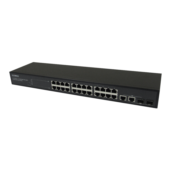
24 10/100tx + 2 10/100/1000t/ mini-gbic combo web smart switch
Hide thumbs
1
2
3
Table Of Contents
4
5
6
7
8
9
10
11
12
13
14
15
16
17
18
19
20
21
22
23
24
25
26
27
28
29
30
31
32
33
34
35
36
37
38
39
40
41
42
43
44
45
46
47
48
49
50
51
52
53
54
55
56
57
58
59
page
of
59
Go
/
59
Contents
Table of Contents
Troubleshooting
Bookmarks
Table of Contents
Ce Mark Warning
Fcc Warning
Table of Contents
Introduction
Features
Package Contents
Hardware Description
Physical Dimensions
Front Panel
LED Indicators
Gigabit Port LED Indicator
Rear Panel
Desktop Installation
Attaching Rubber Pads
Rack-Mounted Installation
Power on
Network Application
Small Workgroup
Segment Uplink
Web-Based Management
About Web-Based Management
User Login
Main Page
Administrator
Authentication Configuration
System IP Configuration
System Status
Default Switch Setting and Reboot
Port Management
Port Configuration
Port Mirroring
Bandwidth Control
Broadcast Storm Control
VLAN Setting
VLAN Member Setting (Port Based)
VLAN Mode
VLAN PVID Index Setting
Per Port Counter
Qos Setting
Priority Mode
Class of Service Configuration
Security Filter
Trunk
Trunk Configuration
Aggregation Information
Configuration Backup/Recovery
Firmware Update
Reboot
Logout
Troubleshooting
Incorrect Connections
Faulty or Loose Cables
Non-Standard Cables
Improper Network Topologies
Diagnosing LED Indicators
Cabling
Technical Specification
Appendix
10 /100BASE-TX Pin Outs
10/100Base-TX Cable Schematic
10/100/1000Base-TX Pin Outs
10/100/1000Base-TX Cable Schematic
Advertisement
Quick Links
Download this manual
Table of
Contents
Previous
Page
Next
Page
1
2
3
4
5
Advertisement
Table of Contents
Need help?
Do you have a question about the 24 10 and is the answer not in the manual?
Ask a question
Questions and answers
Related Manuals for Edimax 24 10
Switch Edimax ES-5226RS Specifications
24 10/100tx + 2 10/100/1000t /mini- gbic combo web smart switch (3 pages)
Switch Edimax Edimax ES-3105P Quick Installation Manual
Edimax 5/8/16 ports soho fast ethernet switches quick installation guide (40 pages)
Switch Edimax ES-3116RE+ User Manual
Edimax technology user's guide 16-port 10/100mbps smart switch es-3116re+ (16 pages)
Switch Edimax EK-PA2C Manual
Ce doc (1 page)
Switch Edimax ES-3308P V2 Datasheet
8-port fast ethernet desktop switch (3 pages)
Switch Edimax EK-UAK2 Quick Installation Manual
2/4 ports usb kvm switches (2 pages)
Switch Edimax EK-UAK4 Manual
Ce doc (1 page)
Switch Edimax ES-3305P V3 Quick Installation Manual
5/8-port fast ethernet desktop switch (10 pages)
Switch Edimax ES-1016 Datasheet
16-port fast ethernet rack-mount switch (2 pages)
Switch Edimax GS-5424PLX V2 Quick Installation Manual
(23 pages)
Switch Edimax ES-3205P Datasheet
5 ports fast ethernet switch (2 pages)
Switch Edimax ES-3205P Manual
Ce doc (1 page)
Switch Edimax ES-3305P Quick Installation Manual
5 / 8 / 16 port fast ethernet desktop switch (8 pages)
Switch Edimax ES-3208P Datasheet
8 ports fast ethernet switch (2 pages)
Switch Edimax GS-1016 Datasheet
16-port gigabit rack-mount switch (2 pages)
Switch Edimax GS-3008P User Manual
(43 pages)
This manual is also suitable for:
100tx + 2 10
100
1000t
Es-5226rs
Table of Contents
Print
Rename the bookmark
Delete bookmark?
Delete from my manuals?
Login
Sign In
OR
Sign in with Facebook
Sign in with Google
Upload manual
Upload from disk
Upload from URL


Need help?
Do you have a question about the 24 10 and is the answer not in the manual?
Questions and answers