Advertisement
Quick Links
All manuals and user guides at all-guides.com
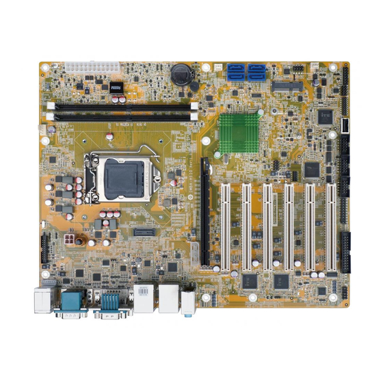
ATX motherboard supports 14nm LGA1151 6th Generation Intel®
Core™ i7/i5/i3, Celeron® and Pemtium® processor, DDR4,
dual independent displays DVI-I/HDMI/iDP, dual Intel® GbE LAN,
USB 3.0, SATA 6Gb/s, HD Audio and RoHS
IMBA-H110
Quick Installation Guide
Version 1.0
Jan 19, 2017.
Package List
IMBA-H110 package includes the following items:
1 x IMBA-H110 single board computer
1 x I/O shielding
2 x SATA cable
1 x One Key Recovery CD
1 x QIG
1 x Utility CD
©2006 Copyright by IEI Integration corp.
All rights reserved.
1
Advertisement

Related Manuals for IEI Technology IMBA-H110


Summary of Contents for IEI Technology IMBA-H110
- Page 1 IMBA-H110 Quick Installation Guide Version 1.0 Jan 19, 2017. Package List IMBA-H110 package includes the following items: 1 x IMBA-H110 single board computer 1 x I/O shielding 2 x SATA cable 1 x One Key Recovery CD 1 x QIG 1 x Utility CD ©2006 Copyright by IEI Integration corp.
-
Page 2: Specifications
All manuals and user guides at all-guides.com Specifications CPU: LGA1151 socket supports 6th generation Intel® Core™ i7/i5/i3, Celeron® and Pentium® processor Chipset: Intel® H110 Memory: Two 288-pin 2133 MHz dual-channel DDR4 SDRAM unbuffered DIMMs support up to 64 GB BIOS: UEFI BIOS Graphic Engine: Intel®... - Page 3 All manuals and user guides at all-guides.com 2 x USB 2.0 (2x4 pin, P=2.54) 4 x SATA 6Gb/s (support hot plug) Audio: Realtek ALC662 HD codec supports 5.1-channel 3 x Audio jacks (line-out, line-in, mic-in) on rear IO 1 x Front audio (2x5 pin) Front Panel: 1 x Front panel (2x7 pin, power LED, HDD LED, speaker, power button, reset button)
-
Page 4: Ordering Information
All manuals and user guides at all-guides.com Ordering Information IMBA-H110-R10: ATX motherboard supports 14nm LGA1151 6th Generation Intel® Core™ i7/i5/i3, Celeron® and Pemtium® processor, DDR4, dual independent displays DVI-I/HDMI/iDP, dual Intel® GbE LAN, SATA 6Gb/s, USB 3.0, HD Audio and RoHS 19800-000049-RS: LPT cable, 25-pin (2x13) female, P=2.54... -
Page 5: Jumpers Setting And Connectors
All manuals and user guides at all-guides.com Jumpers setting and connectors LABEL FUNCTION J_ATX_AT1 AT/ATX mode select switch J_CMOS1 Clear CMOS button USB SW1, USB SW2 USB power setting J_FLASH1 Flash Descriptor Security Override F_PANEL1 PWR & RST Buttons and indicators VIDEO1 DVI-I Connector HDMI1... - Page 6 All manuals and user guides at all-guides.com SMB1 SMBUS Connector I2C1 I2C Connector (to EC) LED_LAN1 LAN1 LINK LED Connector LED_LAN2 LAN2 LINK LED Connector CHASSIS1 Chassis Status Connector J_ATX_AT1: AT/ATX mode select switch PIN NO. DESCRIPTION Short 1 - 2 ATX Mode (default) Short 2 - 3 AT Mode...
- Page 7 All manuals and user guides at all-guides.com USB SW1, USB SW2: USB power setting USB SW1 DESCRIPTION +5V DUAL Normal Operation (default) Aptio Setup Utility – Copyright (C) 2012 American Megatrends, Inc. Chipset Auto Power Button Status [Disabled(ATX)] Restore AC Power Loss [Last State] ------------------ >...
- Page 8 All manuals and user guides at all-guides.com VIDEO1: 15-pin Female Connector PIN NO. DESCRIPTION PIN NO. DESCRIPTION GREEN BLUE DDCDA HSYNC VSYNC DDCCLK VIDEO1: DVI-I(Dual Link) PIN NO. DESCRIPTION PIN NO. DESCRIPTION DVI_DATA1 GREEN BLUE DVI_DATA2# HPDET DVI_DATA2 DVI_DATA0# DVI_DATA0 DDC CLK DDC DATA DVI_CLK...
- Page 9 All manuals and user guides at all-guides.com HDMI1: HDMI Connector PIN NO. DESCRIPTION PIN NO. DESCRIPTION HDMI_DATA2 HDMI_DATA2# HDMI_SCL HDMI_DATA1 HDMI_SDA HDMI_DATA1# HDMI_DATA0 HDMI_HPD HDMI_GND HDMI_DATA0# HDMI_GND HDMI_CLK HDMI_GND HDMI_GND HDMI_CLK# DP1 : Internal Connector PIN NO. DESCRIPTION PIN NO. DESCRIPTION AUXP LANE1N...
- Page 10 All manuals and user guides at all-guides.com LAN1_USB1: Ethernet and USB 3.0 connectors USB1: External USB 3.0 connectors PIN NO. DESCRIPTION PIN NO. DESCRIPTION USB_DATA- USB_DATA- USB_DATA+ USB_ DATA+ USB3_RX- USB3_RX- USB3_RX+ USB3_ RX+ USB3_TX- USB3_TX- USB3_TX+ USB3_TX+ LAN1: RJ-45 LAN connector PIN NO.
- Page 11 All manuals and user guides at all-guides.com LAN2_USB2: Ethernet and USB 3.0 connectors USB2: External USB 3.0 connectors PIN NO. DESCRIPTION PIN NO. DESCRIPTION USB_DATA- USB_DATA- USB_DATA+ USB_ DATA+ USB3_RX- USB3_RX- USB3_RX+ USB3_ RX+ USB3_TX- USB3_TX- USB3_TX+ USB3_TX+ LAN2: RJ-45 LAN connector PIN NO.
- Page 12 All manuals and user guides at all-guides.com KB_MS1: 6-pin header Keyboard/Mouse Connector PIN NO. DESCRIPTION PIN NO. DESCRIPTION Mouse Data Mouse Clock Keyboard Data Keyboard Clock USB3-1 : Internal USB 3.0 Connector PIN NO. DESCRIPTION PIN NO. DESCRIPTION USB_DATA+ USB3_RX- USB_DATA- USB3_RX+ USB3_TX+...
- Page 13 All manuals and user guides at all-guides.com COM3, COM4: Internal RS-232 serial port connectors PIN NO. DESCRIPTION PIN NO. DESCRIPTION COM5: Internal RS-232/422/485 serial port connectors PIN NO. DESCRIPTION PIN NO. DESCRIPTION AUDIO_CV1 : Audio Line-In/Out MIC Connector PIN NO. DESCRIPTION Line_In CD/DVD or other audio source input port...
- Page 14 All manuals and user guides at all-guides.com FRONT-PANEL1 : Audio Source Connector PIN NO. DESCRIPTION PIN NO. DESCRIPTION MIC2-L MIC2-R Presence# LINE2-R MIC2-JD FRONT-IO LINE2-JD LINE2-L SATA1, SATA2, SATA3: Serial ATA 3.0 connectors PIN NO. DESCRIPTION PIN NO. DESCRIPTION SATA_RX- SATA_TX+ SATA RX+ SATA_TX-...
- Page 15 All manuals and user guides at all-guides.com CN2: M-SATA card connector PIN NO. DESCRIPTION PIN NO. DESCRIPTION PCIE_WAKE# +3.3V 1.5V MSATA_CLK# MSATA _CLK PLTRST_N +3.3V PLTRST_N SATA_RX+ +3.3V SATA_RX- 1.5V SMB_CLK SATA_TX- SMB_DATA SATA_TX+ USB_DATA- USB_DATA+ +3.3V +3.3V +3.3V CLINK_CLK CLINK_DATA 1.5V CLINK_RST#...
- Page 16 All manuals and user guides at all-guides.com SYS_FAN1, SYS_FAN2: System fan connector PIN NO. DESCRIPTION PIN NO. DESCRIPTION FANIO +12V (PWM) DIO1 : Digital Input / Output Connector PIN NO. DESCRIPTION PIN NO. DESCRIPTION Output 3 Output 2 Output 1 Output 0 Input 3 Input 2...
- Page 17 All manuals and user guides at all-guides.com ATXPWR1: Additional Power Source Connector PIN NO. DESCRIPTION PIN NO. DESCRIPTION +12V TPM1: Trusted Platform Module Connector PIN NO. DESCRIPTION PIN NO. DESCRIPTION LCLK LFRAME# LRERST# LAD3 LAD2 +3.3V LAD1 LAD0 SB3V SERIRQ GLKRUN# LPCPD# LDRQ#...
- Page 18 All manuals and user guides at all-guides.com JSPI1: Flash SPI ROM connector PIN NO. DESCRIPTION PIN NO. DESCRIPTION +3.3V SPI_CS# SPI_SO SPI_CLK SPI_SI JSPI2: Flash EC ROM connector PIN NO. DESCRIPTION PIN NO. DESCRIPTION +3.3V SPI_CS# SPI_SO SPI_CLK SPI_SI SMB1: SMBus Connector PIN NO.
- Page 19 All manuals and user guides at all-guides.com Board Layout: Jumper and Connector Locations (Unit: mm)
Need help?
Do you have a question about the IMBA-H110 and is the answer not in the manual?
Questions and answers