Table of Contents

Related Manuals for IEI Technology IMBA-9454B


Summary of Contents for IEI Technology IMBA-9454B
-
Page 1: User Manual
IMBA-9454B ATX Motherboard MODEL: IMBA-9454B ATX Motherboard, Dual VGA, Eight RS-232 Serial Ports Supports Intel® Core™2 Duo, 4.0 GB DDR2, GbE, PCIe x1 PCIe Mini, 3x PCI and RoHS Compliant User Manual Page i Rev. 1.00 – 4 February, 2009... - Page 2 IMBA-9454B ATX Motherboard Revision Date Version Changes 4 February, 2009 1.00 Initial release Page ii...
- Page 3 IMBA-9454B ATX Motherboard Copyright COPYRIGHT NOTICE The information in this document is subject to change without prior notice in order to improve reliability, design and function and does not represent a commitment on the part of the manufacturer. In no event will the manufacturer be liable for direct, indirect, special, incidental, or consequential damages arising out of the use or inability to use the product or documentation, even if advised of the possibility of such damages.
-
Page 4: Packing List
IMBA-9454B from or contact an IEI sales representative directly. To contact an IEI sales representative, please send an email to sales@iei.com.tw. The items listed below should all be included in the IMBA-9454B package. 1 x IMBA-9454B 2 x 4 port RS-232 cable... -
Page 5: Table Of Contents
IMBA-9454B ATX Motherboard Table of Contents 1 INTRODUCTION......................1 1.1 I ......................2 NTRODUCTION 1.2 F ........................2 EATURES 1.3 O ........................2 VERVIEW 1.4 P ..............3 ERIPHERAL ONNECTORS AND UMPERS 1.5 T ..................4 ECHNICAL PECIFICATIONS 2 DETAILED SPECIFICATIONS .................. 7 2.1 O... - Page 6 IMBA-9454B ATX Motherboard 2.9.3 Super I/O......................14 2.9.3.1 Enhanced Hardware Monitor..............14 2.9.3.2 Fan Speed Controller ................14 2.9.3.3 Parallel Port....................14 2.9.3.4 Keyboard and Mouse Controller............... 14 2.10 E ............. 14 NVIRONMENTAL AND OWER PECIFICATIONS 2.10.1 System Monitoring ..................14 2.10.2 Operating Temperature and Temperature Control.........
- Page 7 IMBA-9454B ATX Motherboard 4.2.12 Serial Port Connector 1 ................. 34 4.2.13 Serial Port Connector 2 ................. 35 4.2.14 SPI Flash Connector..................36 4.2.15 USB Connectors (Internal) ................37 4.3 E ........... 38 XTERNAL ERIPHERAL NTERFACE ONNECTORS 4.3.1 Keyboard/Mouse Connector ................39 4.3.2 Parallel Port Connector ..................
- Page 8 IMBA-9454B ATX Motherboard 5.7.6 SATA Drive Connection ................... 67 5.8 E ........... 69 XTERNAL ERIPHERAL NTERFACE ONNECTION 5.8.1 PS/2 Keyboard/Mouse Connection ..............69 5.8.2 Parallel Device Connection................70 5.8.3 RJ-45 Ethernet Connection................71 5.8.4 USB Connection....................71 5.8.5 Audio Connection..................... 72 5.8.6 VGA Monitor Connection ................
- Page 9 IMBA-9454B ATX Motherboard 6.5.4 Removable Drives ...................115 6.5.5 CD/DVD Drives ....................116 6.6 S ........................116 ECURITY 6.7 C ........................118 HIPSET 6.7.1 Northbridge Configuration ................120 6.8 E ........................122 7 DRIVER INSTALLATION..................124 7.1 A ................125 VAILABLE OFTWARE RIVERS 7.2 D CD A ..................
- Page 10 IMBA-9454B ATX Motherboard F.2 C ..................161 OMPATIBLE ROCESSORS F.3 C ................162 OMPATIBLE EMORY ODULES G HAZARDOUS MATERIALS DISCLOSURE ............163 G.1 H IPB P AZARDOUS ATERIALS ISCLOSURE ABLE FOR RODUCTS ERTIFIED AS HS C 2002/95/EC W ........164...
- Page 11 Figure 4-14: Serial Port Connector 2 Location ................35 Figure 4-15: SPI Flash Connector ....................37 Figure 4-16: USB Connector Pinout Locations .................38 Figure 4-17: IMBA-9454B External Interface Connectors............39 Figure 4-18: PS/2 Pinouts ......................39 Figure 4-19: Parallel Port Connector Pinout Locations............40 Figure 4-20: Ethernet Connector Pinout Locations ..............41 Figure 4-21: Ethernet Connector....................42...
- Page 12 Figure 5-2: Remove the CPU Socket Protective Shield ............50 Figure 5-3: Open the CPU Socket Load Plate................51 Figure 5-4: Insert the LGA775 CPU.....................52 Figure 5-5: IEI Cooling Kit......................53 Figure 5-6: Securing the Heat sink to the PCB Board ..............54 Figure 5-7: Installing a DIMM.......................55 Figure 5-8: Jumper Locations .....................57...
- Page 13 IMBA-9454B ATX Motherboard Figure 7-14: VGA Driver Installing ................... 134 Figure 7-15: Intel® Graphics Media Accelerator Installation Complete....... 134 Figure 7-16: LAN Driver Directory.................... 135 Figure 7-17: LAN Driver Welcome.................... 136 Figure 7-18: LAN Driver Installation Ready ................136 Figure 7-19: Device Manager List .................... 137 Figure 7-20: Audio Driver Directory..................
- Page 14 IMBA-9454B ATX Motherboard List of Tables Table 1-1: Technical Specifications....................6 Table 2-1: Power Consumption....................16 Table 3-1: Package List Contents ....................20 Table 3-2: Optional Components ....................21 Table 4-1: Peripheral Interface Connectors ................24 Table 4-2: External Peripheral Interface Panel Connectors .............25 Table 4-3: ATX Power Supply Connector (4-pins) Pinouts ............26 Table 4-4: ATX Power Connector Pinouts .................27...
- Page 15 IMBA-9454B ATX Motherboard Table 5-9: COM3 Voltage Setting ....................60 Table 5-10: COM4 RI/Voltage Selection..................61 Table 5-11: COM4 Voltage Setting ....................61 Table 5-12: IEI Provided Cables ....................62 Table 6-1: BIOS Navigation Keys ....................77 Page xv...
- Page 16 IMBA-9454B ATX Motherboard BIOS Menus BIOS Menu 1: Main ........................78 BIOS Menu 2: Advanced ......................80 BIOS Menu 3: CPU Configuration ....................81 BIOS Menu 4: IDE Configuration....................82 BIOS Menu 5: IDE Master and IDE Slave Configuration ............84 BIOS Menu 6: Floppy Configuration...................89 BIOS Menu 7: Super IO Configuration..................90...
-
Page 17: Introduction
IMBA-9454B ATX Motherboard Chapter Introduction Page 1... -
Page 18: Introduction
The IMBA-9454B also features six USB ports, four SATA II ports, an IDE port, a FDD port, a parallel port, three PCI slots, a PCIe x1 slot and a PCIe Mini card slot. -
Page 19: Peripheral Connectors And Jumpers
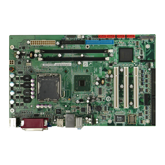
IMBA-9454B ATX Motherboard Figure 1-1: Overview 1.4 Peripheral Connectors and Jumpers The IMBA-9454B has the following on-board connectors: 1 x 12 V power connector 1 x ATX power connector 1 x Audio connector 1 x Audio line out connector 2 x DDR2 DIMM slots... -
Page 20: Technical Specifications
2 x Serial port connectors (4 ports per connector) 1 x SPI flash connector 2 x USB connectors The IMBA-9454B has the following external peripheral interface connectors on the board rear panel: 1 x PS/2 dual keyboard/mouse connector 1 x Parallel port connector... - Page 21 IMBA-9454B ATX Motherboard Specification IMBA-9454B Intel® Core™ 2 Duo (up to 2.66 GHz) Intel® Pentium® 4 (up to 3.8 GHz) System CPU Intel® Pentium® D (up to 3.6 GHz) Intel® Celeron® D (up to 3.6 GHz) (Hyperthreading Technology supported) Front Side Bus 533 MHz, 800 MHz or 1066 MHz Northbridge: Intel®...
-
Page 22: Table 1-1: Technical Specifications
IMBA-9454B ATX Motherboard Specification IMBA-9454B 304 mm x 190 mm Dimensions Weight (GW/NW) 1200 g / 650 g Table 1-1: Technical Specifications Page 6... -
Page 23: Detailed Specifications
IMBA-9454B ATX Motherboard Chapter Detailed Specifications Page 7... -
Page 24: Overview
IMBA-9454B ATX Motherboard 2.1 Overview This chapter describes the specifications and on-board features of the IMBA-9454B in detail. 2.2 Dimensions The dimensions of the board are listed below and shown in Figure 2-1. Length: 304 mm Width: 190 mm Figure 2-1: IMBA-9454B Dimensions (mm) External peripheral interface connector panel dimensions are shown in Figure 2-2. -
Page 25: Data Flow
IMBA-9454B ATX Motherboard 2.3 Data Flow Figure 2-3 shows the data flow between the two on-board chipsets and other components installed on the motherboard and described in the following sections of this chapter. Figure 2-3: Data Flow Block Diagram Page 9... -
Page 26: Compatible Processors
IMBA-9454B ATX Motherboard 2.4 Compatible Processors The IMBA-9454B support LGA775 Intel® processors. Processors supported by the IMBA-9454B include the Core™2 Duo, Pentium® 4, Pentium® D and Celeron® D. Figure 2-4: CPU & Northbridge 2.5 Intel® 945G Northbridge Chipset The CPU connects to the Intel® 945G Northbridge chip. The Northbridge is connected to main memory and to the graphics interfaces. -
Page 27: Intel® Ich7 Southbridge Chipset
IMBA-9454B ATX Motherboard 2.6 Intel® ICH7 Southbridge Chipset The Southbridge chipset is connected to the interfaces listed in the subsections below. Figure 2–5: Southbridge 2.6.1 Audio The audio controller supports line output, line input and microphone input through audio jacks on the rear I/O panel. -
Page 28: Sata Controller
Supports 3.0 Gb/s data transfer speeds 2.6.6 USB Controller Six USB ports are supported on the IMBA-9454B. Two USB ports are located on the rear I/O panel, four more are accessible through two pin-headers on the board. 2.7 PCIe Bus Components... -
Page 29: Pci Bus Components
IMBA-9454B ATX Motherboard 2.8 PCI Bus Components The PCI bus is connected to the following components: Three PCI expansion card slots 2.8.1 PCI Expansion Card Slot PCI expansion card slots provide an expansion card interface for a number of legacy cards. -
Page 30: Super I/O
The Super I/O keyboard controller can execute the 8042 instruction set. 2.10 Environmental and Power Specifications This section outlines the system environmental and power specifications. 2.10.1 System Monitoring The IMBA-9454B monitors the following thermal inputs: System temperature Power temperature CPU temperature... -
Page 31: Operating Temperature And Temperature Control
CPU fan speed System fan speed 2.10.2 Operating Temperature and Temperature Control The maximum and minimum operating temperatures for the IMBA-9454B are listed below. Minimum Operating Temperature: 0ºC (32°F) Maximum Operating Temperature: 60°C (140°F) A cooling fan and heat sink must be installed on the CPU. Thermal paste must be smeared on the lower side of the heat sink before it is mounted on the CPU. -
Page 32: Table 2-1: Power Consumption
IMBA-9454B ATX Motherboard Voltage Current +12 V 10.44 A Table 2-1: Power Consumption Page 16... -
Page 33: Unpacking
IMBA-9454B ATX Motherboard Chapter Unpacking Page 17... -
Page 34: Anti-Static Precautions
Electrostatic discharge (ESD) can cause serious damage to electronic components, including the IMBA-9454B. Dry climates are especially susceptible to ESD. It is critical that the following anti-static precautions are strictly adhered to whenever handling the IMBA-9454B or any other electrical component. -
Page 35: Unpacking Checklist
3.3 Unpacking Checklist NOTE: If any components listed in the checklist below are missing, do not proceed with the installation. Contact the IEI reseller or vendor the IMBA-9454B was purchased from or contact an IEI sales representative directly by sending an email to sales@iei.com.tw. -
Page 36: Optional Components
Item and Part Number Image Quick Installation Guide Utility CD Table 3-1: Package List Contents 3.3.2 Optional Components The following optional components are available from IEI. Item and Part Number Image CPU cooling kit (P/N: CF-775A-RS) CPU cooler (P/N: CF-520-RS) -
Page 37: Table 3-2: Optional Components
IMBA-9454B ATX Motherboard Item and Part Number Image Wireless LAN card 802.11b/g (P/N: WMPCIE-V01-RS) Wireless LAN card 802.11b/g (P/N: WMUSB-V01-RS) Dual USB cable (P/N: CB-USB02-RS) Table 3-2: Optional Components Page 21... -
Page 38: Connector Pinouts
IMBA-9454B ATX Motherboard Chapter Connector Pinouts Page 22... -
Page 39: Peripheral Interface Connectors
Figure 4-1 shows the on-board peripheral connectors, rear panel peripheral connectors and on-board jumpers. Figure 4-1: Connector and Jumper Locations 4.1.2 Peripheral Interface Connectors Table 4-1 shows a list of the peripheral interface connectors on the IMBA-9454B. Detailed descriptions of these connectors can be found below. Page 23... -
Page 40: External Peripheral Interface Panel Connectors
JSPI1 USB connector 8-pin header USB2 Table 4-1: Peripheral Interface Connectors 4.1.3 External Peripheral Interface Panel Connectors Table 4-2 lists the external peripheral interface panel connectors on the IMBA-9454B. Detailed descriptions of these connectors can be found in. Page 24... -
Page 41: Internal Peripheral Connectors
Internal peripheral connectors are found on the motherboard and are only accessible when the motherboard is outside of the chassis. This section has complete descriptions of all the internal, peripheral connectors on the IMBA-9454B. 4.2.1 ATX Power Supply Connector (4-pins) -
Page 42: Atx Power Supply Connector (24-Pins)
IMBA-9454B ATX Motherboard DESCRIPTION +12 V +12 V Table 4-3: ATX Power Supply Connector (4-pins) Pinouts 4.2.2 ATX Power Supply Connector (24-pins) CN Label: PWR1 CN Type: 24-pin ATX power connector (2x12) CN Location: See Figure 4-3 CN Pinouts: See Table 4-4 The 24-pin ATX power supply connector is connected to a ATX power supply. -
Page 43: Fan Connectors
IMBA-9454B ATX Motherboard DESCRIPTION DESCRIPTION +5.0 V Ground Ground Ground PWR-OK -5.0 V 5 VSB +5.0 V +12.0 V +5.0 V +12.0 V +5.0 V +3.3 V Ground Table 4-4: ATX Power Connector Pinouts 4.2.3 Fan Connectors CN Label: CPU_FAN1 & SYS_FAN1 CN Type: 4-pin wafer connector &... -
Page 44: Floppy Disk Connector
IMBA-9454B ATX Motherboard CPU_FAN1 SYS_FAN1 +12 V +12 V Rotation Signal Rotation Signal Control Table 4-5: Fan Connectors Pinouts 4.2.4 Floppy Disk Connector CN Label: FDC1 CN Type: 34-pin header (2x17) CN Location: See Figure 4-5 The floppy disk connector is connected to a floppy disk drive. -
Page 45: Ide Connector
Reset button- Table 4-6: Multi-panel Connector Pinouts 4.2.6 IDE Connector CN Label: 40-pin box header (2x20) CN Type: See Figure 4-7 CN Location: One 40-pin IDE device connector on the IMBA-9454B supports connectivity to two hard disk drives. Page 29... -
Page 46: Line Out Connector
IMBA-9454B ATX Motherboard Figure 4-7: IDE Device Connector Locations 4.2.7 Line Out Connector CN Label: LINE_OUT1 CN Type: 4-pin header (1x4) CN Location: See Figure 4-8 See Table 4-7 CN Pinouts: The line out connector provides audio output that can be connected to the front panel. -
Page 47: Pcie Mini Card Slot
IMBA-9454B ATX Motherboard DESCRIPTION Line out left Ground Ground Line out right Table 4-7: Line Out Connector Pinouts 4.2.8 PCIe Mini Card Slot CN Label: MINI_PCIE1 PCIe Mini card slot CN Type: CN Location: See Figure 4-9 A PCIe Mini expansion card can be installed in the PCIe Mini card slot. -
Page 48: Pci Slot
IMBA-9454B ATX Motherboard Figure 4-10: PCIe x1 Expansion Card Slot 4.2.10 PCI Slot CN Label: PCI1 to PCI3 CN Type: PCI Slot See Figure 4-11 CN Location: The PCI slot enables a PCI expansion module to be connected to the board. -
Page 49: Sata Drive Connectors
IMBA-9454B ATX Motherboard 4.2.11 SATA Drive Connectors CN Label: SATA1, SATA2, SATA3 and SATA4 7-pin SATA drive connectors CN Type: CN Location: See Figure 4-12 CN Pinouts: See Table 4-8 The SATA drive connectors are connected to SATA 3 Gb/s disk drives that transfer data at speeds as high as 3.0 Gb/s. -
Page 50: Serial Port Connector 1
IMBA-9454B ATX Motherboard 4.2.12 Serial Port Connector 1 CN Label: COM1-4 40-pin box header (2x20) CN Type: CN Location: See Figure 4-13 CN Pinouts: See Table 4-9 The serial port connector provides a connection for four serial ports. These serial ports also support a selectable pin-9. -
Page 51: Serial Port Connector 2
IMBA-9454B ATX Motherboard DESCRIPTION DESCRIPTION TXD3 CTS3 DTR3 DCD4 DSR4 RXD4 RTS4 TXD4 CTS4 DTR4 Table 4-9: Serial Port Connector 1 Pinouts 4.2.13 Serial Port Connector 2 CN Label: COM5-8 CN Type: 40-pin header (2x20) CN Location: See Figure 4-14... -
Page 52: Spi Flash Connector
IMBA-9454B ATX Motherboard DESCRIPTION DESCRIPTION TXD5 CTS5 DTR5 DCD6 DSR6 RXD6 RTS6 TXD6 CTS6 DTR6 DCD7 DSR7 RXD7 RTS7 TXD7 CTS7 DTR7 DCD8 DSR8 RXD8 RTS8 TXD8 CTS8 DTR8 Table 4-10: Serial Port Connector 2 Pinouts 4.2.14 SPI Flash Connector... -
Page 53: Usb Connectors (Internal)
IMBA-9454B ATX Motherboard Figure 4-15: SPI Flash Connector DESCRIPTION SPI_VCC Ground SPI_CS- SPICLK SPIMISO SPIMOSI Table 4-11: SPI Flash Connector 4.2.15 USB Connectors (Internal) CN Label: USB2 CN Type: 8-pin header (2x4) CN Location: See Figure 4-16 See Table 4-12 CN Pinouts: The USB header connects to two USB ports. -
Page 54: External Peripheral Interface Connectors
Table 4-12: USB Port Connector Pinouts 4.3 External Peripheral Interface Connectors The external peripheral interface connectors on the back panel are connected to devices externally when the IMBA-9454B is installed in a chassis. The peripheral connectors on the rear panel are: 1 x Keyboard/mouse connector... -
Page 55: Keyboard/Mouse Connector
CN Type: PS/2 connector CN Location: See Figure 4-17 (labeled number 1) CN Pinouts: See Figure 4-18 and Table 4-13 The IMBA-9454B keyboard and mouse connectors are standard PS/2 connectors. Figure 4-18: PS/2 Pinouts DESCRIPTION DESCRIPTION L_KDAT L_MDAT Page 39... -
Page 56: Parallel Port Connector
See Figure 4-17 (labeled number 2) CN Pinouts: See Figure 4-19 and Table 4-14 These ports are usually connected to a printer. IMBA-9454B includes one on-board parallel ports accessed through one 25-pin D-type female connector. Figure 4-19: Parallel Port Connector Pinout Locations... -
Page 57: Ethernet Connector
IMBA-9454B ATX Motherboard Description Description PRINTER SELECT LN# Table 4-14: Parallel Port Connector Pinouts 4.3.3 Ethernet Connector CN Label: LAN/USB1 RJ-45 ports CN Type: CN Location: See Figure 4-17 (labeled 3) CN Pinouts: See Figure 4-20, Table 4-15 and Table 4-16 A 1 Gb connection can be made between the Ethernet connectors and a Local Area Network (LAN) through a network hub. -
Page 58: Audio Connectors
IMBA-9454B ATX Motherboard DESCRIPTION DESCRIPTION N/C (or MDX2+) N/C (or MDX3-) Table 4-15: Ethernet Connector Pinouts Figure 4-21: Ethernet Connector The RJ-45 Ethernet connector has two status LEDs, one green and one yellow. The green LED indicates activity on the port and the yellow LED indicates the port is linked (Table 4-16). -
Page 59: Usb Connectors
IMBA-9454B ATX Motherboard Microphone (Pink): Connects a microphone. Figure 4-22: Audio Connector 4.3.5 USB Connectors CN Label: LAN/USB1, USB1 CN Type: Dual USB port CN Location: See Figure 4-17 (labeled 5) See Figure 4-23 and Table 4-17 CN Pinouts: USB devices connect directly to the USB connectors on the external peripheral connector panel. -
Page 60: Vga Connector
IMBA-9454B ATX Motherboard 4.3.6 VGA Connector CN Label: VGA1, VGA2 HD-D-sub 15 Female connector CN Type: CN Location: See Figure 4-17 (labeled 6) CN Pinouts: See Figure 4-24 and Table 4-18 The standard HD-D-sub 15 female connector connects to a CRT or LCD monitor. -
Page 61: Installation
IMBA-9454B ATX Motherboard Chapter Installation Page 45... -
Page 62: Anti-Static Precautions
Electrostatic discharge (ESD) can cause serious damage to electronic components, including the IMBA-9454B. Dry climates are especially susceptible to ESD. It is therefore critical that whenever the IMBA-9454B, or any other electrical component is handled, the following anti-static precautions are strictly adhered to. -
Page 63: Installation Notices
Use the product before verifying all the cables and power connectors are properly connected. Allow screws to come in contact with the PCB circuit, connector pins, or its components. 5.2.2 Installation Checklist The following checklist is provided to ensure the IMBA-9454B is properly installed. Page 47... - Page 64 A CPU cooling kit is properly installed Compatible memory modules are properly inserted into the memory slots The IMBA-9454B is installed into a chassis with adequate ventilation The correct power supply is being used The following devices (if applicable) are properly connected...
-
Page 65: Cpu Installation
Running a CPU without a cooling kit may also result in injury to the user. The CPU, CPU cooling kit and DIMM are the most critical components of the IMBA-9454B. If any of these components is not installed, the IMBA-9454B cannot operate. 5.3.1 LGA775 CPU Installation NOTE: To enable Hyper-threading, both the CPU, chipset and operating system must support hyper-threading. -
Page 66: Figure 5-1: Intel Lga775
IMBA-9454B ATX Motherboard Figure 5-1: Intel LGA775 To install a LGA775 CPU onto the IMBA-9454B, follow the steps below: WARNING: When handling the CPU, only hold it on the sides. DO NOT touch the pins at the bottom of the CPU. -
Page 67: Figure 5-3: Open The Cpu Socket Load Plate
IMBA-9454B ATX Motherboard Step 2: Open the socket. Disengage the load lever by pressing the lever down and slightly outward to clear the retention tab. Rotate the load lever to a fully open position. Then rotate the load plate towards the opposite direction. See Figure 5-3. -
Page 68: Lga775 Cooling Kit Installation
It is strongly recommended that the original heat sink and cooler provided by Intel not be used on the IMBA-9454B. IEI’s cooling kits include a support bracket that is combined with the heat sink mounted on the CPU to counterweigh and balance the load on both sides of the PCB. -
Page 69: Figure 5-5: Iei Cooling Kit
IMBA-9454B ATX Motherboard Figure 5-5: IEI Cooling Kit The cooling kit can be purchased separately. The cooling kits comprise of a CPU heat sink and a cooling fan. WARNING: Do not wipe off (accidentally or otherwise) the pre-sprayed layer of thermal paste on the bottom of the heat sink. -
Page 70: Dimm Installation
Step 6: Connect the fan cable. Connect the cooling kit fan cable to the fan connector on the IMBA-9454B. Carefully route the cable and avoid heat generating chips and fan blades.Step 0: 5.4 DIMM Installation... -
Page 71: Figure 5-7: Installing A Dimm
IMBA-9454B ATX Motherboard Figure 5-7: Installing a DIMM Step 1: Open the DIMM socket handles. The DIMM socket has two handles that secure the DIMM into the socket. Before the DIMM can be inserted into the socket, the handles must be opened. See Figure 5-7. -
Page 72: Jumper Settings
OPEN a jumper means removing the plastic clip from a jumper. Before the IMBA-9454B is installed in the system, the jumpers must be set in accordance with the desired configuration. The jumpers on the IMBA-9454B are listed in Table 5-1. -
Page 73: At/Atx Power Selection
IMBA-9454B ATX Motherboard Description Label Type COM4 pin-9 setup J_COM_F4 6-pin header J_COM_V4 Table 5-1: Jumpers Figure 5-8: Jumper Locations 5.5.1 AT/ATX Power Selection Jumper Label: Jumper Type: 2-pin header Jumper Settings: See Table 5-2 Jumper Location: See Figure 5-8 This jumper sets the motherboard to use AT or ATX power. -
Page 74: Clear Cmos Jumper
Jumper Location: See Figure 5-8 If the IMBA-9454B fails to boot due to improper BIOS settings, the clear CMOS jumper clears the CMOS data and resets the system BIOS information. To do this, use the jumper cap to close pins 2 and 3 for a few seconds then reinstall the jumper clip back to pins 1 and 2. -
Page 75: Com1 Pin-9 Setup
IMBA-9454B ATX Motherboard 5.5.3 COM1 Pin-9 Setup Jumper Label: J_COM_F1 & J_COM_V1 6-pin header (both settings on the same physical pin header set) Jumper Type: Jumper Settings: See Table 5-4 and Table 5-5 Jumper Location: See Figure 5-8 This jumper sets the function of pin-9 as either RI, 5 V or 12 V. -
Page 76: Com3 Pin-9 Setup
IMBA-9454B ATX Motherboard Pins Description 12 V Default Table 5-7: COM2 Voltage Setting 5.5.5 COM3 Pin-9 Setup Jumper Label: J_COM_F3 & J_COM_V3 6-pin header (both settings on the same physical pin header set) Jumper Type: Jumper Settings: See Table 5-8 and Table 5-9... -
Page 77: Chassis Installation
The IMBA-9454B must be installed in a chassis with ventilation holes on the sides allowing airflow to travel over the heat sink surface. In a system with an individual power supply unit, the cooling fan of a power supply can also help generate airflow over the board surface. -
Page 78: Internal Peripheral Device Connections
IMBA-9454B ATX Motherboard 5.7 Internal Peripheral Device Connections The cables listed in Table 5-12 are shipped with the IMBA-9454B. Quantity Type ATA 66/100 flat cable Dual RS-232 cables SATA drive cables SATA drive power cable Table 5-12: IEI Provided Cables 5.7.1 ATA Flat Cable Connection... -
Page 79: Dual Rs-232 Cable Connection
IMBA-9454B ATX Motherboard Figure 5-9: IDE Cable Connection Step 3: Connect the cable to an IDE device. Connect the two connectors on the other side of the cable to one or two IDE devices. Make sure that pin 1 on the cable... -
Page 80: Fdd Cable Connection
0: 5.7.3 FDD Cable Connection The FDD flat cable connects to the IMBA-9454B to one FDD device. To connect an FDD to the IMBA-9454B please follow the instructions below. Step 1: Locate the FDD connector. -
Page 81: Four Serial Port Connector
IMBA-9454B ATX Motherboard Figure 5-11: FDD Cable Connection Step 3: Connect the cable to an FDD device. Connect the connector at the other end of the cable to an FDD device. Make sure that pin 1 on the cable corresponds to pin 1 on the connector.Step 0:... -
Page 82: Pcie Mini Card Installation
IMBA-9454B ATX Motherboard Figure 5-12: Four Serial Port Connector Step 3: Secure the serial ports to the chassis. Tighten the screws on the DB-9 connectors to secure them to the chassis.Step 0: Figure 5-13: Serial Device Connector 5.7.5 PCIe Mini Card Installation To install the PCIe Mini card, please refer to the diagram and instructions below. -
Page 83: Sata Drive Connection
0: 5.7.6 SATA Drive Connection The IMBA-9454B is shipped with SATA drive cables and SATA drive power cable. Follow the steps below to connect the SATA drives to the motherboard. Step 1: Locate the connectors. -
Page 84: Figure 5-15: Sata Drive Cable Connection
IMBA-9454B ATX Motherboard Figure 5-15: SATA Drive Cable Connection Step 3: Connect the cable to the SATA disk. Connect the connector on the other end of the cable to the connector at the back of the SATA drive. See Figure 5-16. -
Page 85: External Peripheral Interface Connection
5.8.1 PS/2 Keyboard/Mouse Connection The IMBA-9454B has a dual PS/2 connector on the external peripheral interface panel. The dual PS/2 connector is used to connect to a keyboard and mouse to the system. Follow the steps below to connect a keyboard and mouse to the IMBA-9454B. -
Page 86: Parallel Device Connection
IMBA-9454B ATX Motherboard Figure 5–17: PS/2 Keyboard/Mouse Connector 5.8.2 Parallel Device Connection The IMBA-9454B has a single female DB-25 connector on the external peripheral interface panel for parallel devices. Follow the steps below to connect a parallel device to the IMBA-9454B. -
Page 87: Ethernet Connection
Step 0: 5.8.3 RJ-45 Ethernet Connection The IMBA-9454B has two RJ-45 Ethernet connectors on the external peripheral interface panel for LAN communications. Follow the steps below to connect an RJ-45 Ethernet connector to the IMBA-9454B. -
Page 88: Audio Connection
Audio signals are interfaced through three phone jack connections. The red phone jack is for Mic In, blue is for Line In and green is for Speaker Out. Follow the steps below to connect audio devices to the IMBA-9454B. Step 5: Locate the audio phone jacks. -
Page 89: Vga Monitor Connection
IMBA-9454B ATX Motherboard Figure 5–21: Audio Connectors 5.8.6 VGA Monitor Connection The IMBA-9454B has a single female DB-15 connector on the external peripheral interface panel for a VGA monitor. Follow the steps below to connect a VGA monitor to the IMBA-9454B. - Page 90 IMBA-9454B ATX Motherboard Step 9: Secure the connector. Secure the VGA connector to the external interface by tightening the two retention screws on either side of the connector. Step 0: Page 74...
-
Page 91: Bios Setup
IMBA-9454B ATX Motherboard Chapter BIOS Setup Page 75... -
Page 92: Introduction
IMBA-9454B ATX Motherboard 6.1 Introduction A licensed copy of AMI BIOS is preprogrammed into the ROM BIOS. The BIOS setup program allows users to modify the basic system configuration. This chapter describes how to access the BIOS setup program and the configuration options that may be changed. -
Page 93: Getting Help
IMBA-9454B ATX Motherboard Function F1 key General help, only for Status Page Setup Menu and Option Page Setup Menu F2 /F3 key Change color from total 16 colors. F2 to select color forward. F10 key Save all the CMOS changes, only for Main Menu Table 6-1: BIOS Navigation Keys 6.1.3 Getting Help... -
Page 94: Main
IMBA-9454B ATX Motherboard 6.2 Main The Main BIOS menu (BIOS Menu 1) appears when the BIOS Setup program is entered. The Main menu gives an overview of the basic system information. BIOS Menu 1: Main System Overview The System Overview lists a brief summary of different system components. The fields in System Overview cannot be changed. -
Page 95: Advanced
IMBA-9454B ATX Motherboard System Memory: Displays the auto-detected system memory. Size: Lists memory size The System Overview field also has two user configurable fields: System Time [xx:xx:xx] Use the System Time option to set the system time. Manually enter the hours, minutes and seconds. -
Page 96: Bios Menu 2: Advanced
IMBA-9454B ATX Motherboard BIOS Menu 2: Advanced Page 80... -
Page 97: Cpu Configuration
IMBA-9454B ATX Motherboard 6.3.1 CPU Configuration Use the CPU Configuration menu (BIOS Menu 3) to view detailed CPU specifications and configure the CPU. BIOS Menu 3: CPU Configuration The CPU Configuration menu (BIOS Menu 3) lists the following CPU details: Module Version: xx.xx... -
Page 98: Ide Configuration
IMBA-9454B ATX Motherboard 6.3.2 IDE Configuration Use the IDE Configuration menu (BIOS Menu 4) to change and/or set the configuration of the IDE devices installed in the system. BIOS Menu 4: IDE Configuration ATA/IDE Configurations [Compatible] Use the ATA/IDE Configurations option to configure the ATA/IDE controller. - Page 99 IMBA-9454B ATX Motherboard Enhanced Configures the on-board ATA/IDE controller to be in EFAULT Enhanced mode. In this mode, IDE channels and SATA channels are separated. This mode supports up to 6 storage devices. Some legacy OS do not support this mode.
-
Page 100: Ide Master, Ide Slave
IMBA-9454B ATX Motherboard 6.3.2.1 IDE Master, IDE Slave Use the IDE Master and IDE Slave configuration menu to view both primary and secondary IDE device details and configure the IDE devices connected to the system. BIOS Menu 5: IDE Master and IDE Slave Configuration Auto-Detected Drive Parameters The “grayed-out”... - Page 101 IMBA-9454B ATX Motherboard interrupt if block mode is not used. Block mode allows transfers of up to 64 KB per interrupt. PIO Mode: Indicates the PIO mode of the installed device. DMA Mode: Adjust the DMA mode options. S.M.A.R.T.: Indicates whether or not the Self-Monitoring Analysis and Reporting Technology protocol is supported.
- Page 102 IMBA-9454B ATX Motherboard Disabled BIOS is prevented from using the LBA mode control on the specified channel. BIOS auto detects the LBA mode control on the specified Auto EFAULT channel. Block (Multi Sector Transfer) [Auto] Use the Block (Multi Sector Transfer) to disable or enable BIOS to auto detect if the device supports multi-sector transfers.
- Page 103 IMBA-9454B ATX Motherboard PIO mode 4 selected with a maximum transfer rate of 16.6 MB/s (This setting generally works with all hard disk drives manufactured after 1999. For other disk drives, such as IDE CD-ROM drives, check the specifications of the drive.) DMA Mode [Auto] Use the DMA Mode BIOS selection to adjust the DMA mode options.
- Page 104 IMBA-9454B ATX Motherboard UDMA3 Ultra DMA mode 3 selected with a maximum data transfer rate of 44 MB/s (To use this mode, it is required that an 80-conductor ATA cable is used.) Ultra DMA mode 4 selected with a maximum data transfer UDMA4 rate of 66.6 MB/s (To use this mode, it is required that an...
-
Page 105: Floppy Configuration
IMBA-9454B ATX Motherboard 6.3.3 Floppy Configuration Use the Floppy Configuration menu to configure the floppy disk drive connected to the system. BIOS Menu 6: Floppy Configuration Floppy A/B Use the Floppy A/B option to configure the floppy disk drive. Options are listed below: Disabled 360 KB 51/4”... -
Page 106: Super Io Configuration
IMBA-9454B ATX Motherboard 6.3.4 Super IO Configuration Use the Super IO Configuration menu (BIOS Menu 7) to set or change the configurations for the FDD controllers, parallel ports and serial ports. BIOS Menu 7: Super IO Configuration Parallel Port Address [378] Use the Parallel Port Address option to select the parallel port base address. - Page 107 IMBA-9454B ATX Motherboard Normal The normal parallel port mode is the standard mode EFAULT for parallel port operation. The parallel port operates in the enhanced parallel port mode (EPP). The EPP mode supports bi-directional communication between the system and the parallel port device and the transmission rates between the two are much faster than the Normal mode.
- Page 108 IMBA-9454B ATX Motherboard Serial Port1 IRQ [4] Sets the IRQ for the serial port. EFAULT Serial Port2 Address [3F8] Sets the base address for the serial port. Disabled EFAULT Serial Port2 IRQ [4] Sets the IRQ for the serial port.
- Page 109 IMBA-9454B ATX Motherboard Disabled EFAULT Serial Port4 IRQ [4] Sets the IRQ for the serial port. EFAULT Serial Port5 Address [3F8] Sets the base address for the serial port. Disabled EFAULT Serial Port5 IRQ [4] Sets the IRQ for the serial port.
- Page 110 IMBA-9454B ATX Motherboard Serial Port6 IRQ [4] Sets the IRQ for the serial port. EFAULT Serial Port7 Address [3F8] Sets the base address for the serial port. Disabled EFAULT Serial Port7 IRQ [4] Sets the IRQ for the serial port.
-
Page 111: Hardware Health Configuration
IMBA-9454B ATX Motherboard 6.3.5 Hardware Health Configuration The Hardware Health Configuration menu (BIOS Menu 8) shows the operating temperature, fan speeds and system voltages. BIOS Menu 8: Hardware Health Configuration CPU/SYS Fan Mode Setting [Full On Mode] Use the CPU/SYS Fan Mode Setting option to configure the second fan. - Page 112 IMBA-9454B ATX Motherboard Temperature limit of OFF Temperature limit of Start Fan start PWM Slope PWM When the CPU FAN Mode Setting option is in the PWM Manual Mode, the following parameters can be set. CPU Fan PWM control Temperature Limit of OFF [000]...
- Page 113 IMBA-9454B ATX Motherboard CPU Fan Start PWM [070] The fan will enter PWM mode when this temperature setting exceeded. PWM Minimum Mode: 0 PWM Maximum Mode: 127 Slope PWM 1 [0.5 PWM] The fan uses this PWM setting when the fan exceeds the temperature above.
-
Page 114: Power Configuration
IMBA-9454B ATX Motherboard 6.3.6 Power Configuration The power configuration menu adjusts the power settings for the different components of the board. BIOS Menu 9: ACPI Configuration Power Supply Mode [BY HARDWARE] The power supply mode setting determines whether AT or ATX power is used. -
Page 115: General Acpi Configuration
IMBA-9454B ATX Motherboard 6.3.6.1 General ACPI Configuration Use the General ACPI Configuration menu (BIOS Menu 10) to select the ACPI state when the system is suspended. BIOS Menu 10: General ACPI Configuration Suspend Mode [S1 (POS)] Use the Suspend Mode option to specify the sleep state the system enters when it is not being used. -
Page 116: Apm Configuration
IMBA-9454B ATX Motherboard 6.3.6.2 APM Configuration The APM Configuration menu (BIOS Menu 11) allows the advanced power management options to be configured. BIOS Menu 11: Advanced Power Management Configuration Power Button Mode [On/Off] Use the Power Button Mode BIOS to specify how the power button functions. - Page 117 IMBA-9454B ATX Motherboard Power Off The system remains off. The system turns on. Power On Last State The system returns to the state just before power loss EFAULT Resume on Ring [Enabled] Use the Resume on Ring BIOS option to enable activity on the RI (ring in) modem line to rouse the system from a suspend or standby state.
-
Page 118: Remote Access Configuration
IMBA-9454B ATX Motherboard Disabled The real time clock (RTC) cannot generate a wake EFAULT event If selected, the following appears with values that Enabled can be selected: RTC Alarm Date (Days) System Time After setting the alarm, the computer turns itself on from a suspend state when the alarm goes off. - Page 119 IMBA-9454B ATX Motherboard Remote Access [Disabled] Use the Remote Access option to enable or disable access to the remote functionalities of the system. Disabled Remote access is disabled. EFAULT Remote access configuration options shown below Enabled appear: Serial Port Number...
- Page 120 IMBA-9454B ATX Motherboard 115200 8,n,1 D EFAULT 57600 8,n,1 38400 8,n,1 19200 8,n,1 09600 8,n,1 NOTE: Identical baud rate setting musts be set on the host (a management computer running a terminal software) and the slave Redirection After BIOS POST [Always] Use the Redirection After BIOS POST option to specify when console redirection should occur.
-
Page 121: Usb Configuration
IMBA-9454B ATX Motherboard 6.3.8 USB Configuration Use the USB Configuration menu (BIOS Menu 13) to read USB configuration information and configure the USB settings. BIOS Menu 13: USB Configuration USB Configuration The USB Configuration field shows the system USB configuration. The items listed are: Module Version: x.xx.x-xx.x... - Page 122 IMBA-9454B ATX Motherboard USB2.0 Controller [Enabled] This option allows the use Hi-Speed USB connectivity. Disabled Enabled EFAULT Legacy USB Support [Enabled] This option allows a USB keyboard and mouse to be used before USB drivers are loaded. A USB keyboard and mouse can be used before the operating system is loaded, for example, to navigate around the BIOS menus.
-
Page 123: Usb Mass Storage Device Configuration
IMBA-9454B ATX Motherboard 6.3.8.1 USB Mass Storage Device Configuration Use the USB Mass Storage Device Configuration menu (BIOS Menu 14) lists the USB mass storage class devices. BIOS Menu 14: USB Mass Storage Device Configuration Page 107... -
Page 124: Pci/Pnp
IMBA-9454B ATX Motherboard 6.4 PCI/PnP Use the PCI/PnP menu (BIOS Menu 15) to configure advanced PCI and PnP settings. BIOS Menu 15: PCI/PnP Configuration IRQ# [Available] Use the IRQ# address to specify what IRQs can be assigned to a particular peripheral device. - Page 125 IMBA-9454B ATX Motherboard IRQ5 IRQ7 IRQ9 IRQ10 IRQ 11 IRQ 14 IRQ 15 DMA Channel# [Available] Use the DMA Channel# option to assign a specific DMA channel to a particular PCI/PnP device. Available The specified DMA is available to be used by...
-
Page 126: Boot
IMBA-9454B ATX Motherboard 54 KB reserved for legacy ISA devices 6.5 Boot Use the Boot menu (BIOS Menu 16) to configure system boot options. BIOS Menu 16: Boot Page 110... -
Page 127: Boot Settings Configuration
IMBA-9454B ATX Motherboard 6.5.1 Boot Settings Configuration Use the Boot Settings Configuration menu (BIOS Menu 17) to configure advanced system boot options. BIOS Menu 17: Boot Settings Configuration Quick Boot [Enabled] Use the Quick Boot BIOS option to make the computer speed up the boot process. - Page 128 IMBA-9454B ATX Motherboard Enabled OEM Logo displayed instead of POST messages AddOn ROM Display Mode [Force BIOS] Use the AddOn ROM Display Mode option to allow add-on ROM (read-only memory) messages to be displayed. The system forces third party BIOS to display...
-
Page 129: Boot Device Priority
IMBA-9454B ATX Motherboard Enabled System configuration information is shown on screen EFAULT after POST. Boot From LAN Support [Disabled] The BOOT From LAN Support option enables the system to be booted from a remote system. Cannot be booted from a remote system through the... -
Page 130: Hard Disk Drives
IMBA-9454B ATX Motherboard Possible boot devices may include: FLOPPY DRIVE CD/DVD 6.5.3 Hard Disk Drives Use the Hard Disk Drives menu to specify the boot sequence of the available HDDs. BIOS Menu 19: Hard Disk Drives When the menu is opened, the HDDs connected to the system are listed as shown below:... -
Page 131: Removable Drives
IMBA-9454B ATX Motherboard 6.5.4 Removable Drives Use the Removable Drives menu (BIOS Menu 20) to specify the boot sequence of the available FDDs. BIOS Menu 20: Removable Drives When the menu is opened, the FDDs connected to the system are listed as shown below:... -
Page 132: Cd/Dvd Drives
IMBA-9454B ATX Motherboard 6.5.5 CD/DVD Drives Use the CD/DVD Drives menu to specify the boot sequence of the available CD/DVD drives. BIOS Menu 21: CD/DVD Drives When the menu is opened, the CD drives and DVD drives connected to the system are... -
Page 133: Bios Menu 22: Security
IMBA-9454B ATX Motherboard BIOS Menu 22: Security Change Supervisor Password Use the Change Supervisor Password to set or change a supervisor password. The default for this option is Not Installed. If a supervisor password must be installed, select this field and enter the password. After the password has been added, Install appears next to Change Supervisor Password. -
Page 134: Chipset
IMBA-9454B ATX Motherboard Boot Sector Virus Protection [Disabled] Use the Boot Sector Virus Protection to enable or disable boot sector protection. Disables the boot sector virus protection Disabled EFAULT Enabled Enables the boot sector virus protection 6.7 Chipset Use the Chipset menu (BIOS Menu 23) to access the Northbridge and Southbridge configuration menus. - Page 135 IMBA-9454B ATX Motherboard Audio Controller [AC’97 Audio Only] The Audio Controller option enables or disables the audio controller. The on-board AC’97 audio controller is AC’97 Audio Only EFAULT enabled. The on-board audio controller is disabled. All Disabled Spread Spectrum Clock [Disabled] Use the Spread Spectrum Clock option to reduce the EMI.
-
Page 136: Northbridge Configuration
IMBA-9454B ATX Motherboard 6.7.1 Northbridge Configuration Use the Northbridge Configuration menu (BIOS Menu 24) to configure the Northbridge chipset. BIOS Menu 24: Northbridge Chipset Configuration Memory Hole [Disabled] Use the Memory Hole option to reserve memory space between 15 MB and 16 MB for ISA expansion cards that require a specified area of memory to work properly. - Page 137 IMBA-9454B ATX Motherboard Initiate Graphic Adapter Use the Initiate Graphic Adapter option to select the graphics controller used as the primary boot device. Select either an integrated graphics controller (IGD) or a combination of PCI graphics controller, a PCI express (PEG) controller or an IGD. Configuration...
-
Page 138: Exit
IMBA-9454B ATX Motherboard 6.8 Exit Use the Exit menu (BIOS Menu 25) to load default BIOS values, optimal failsafe values and to save configuration changes. BIOS Menu 25:Exit Save Changes and Exit Use the Save Changes and Exit option to save the changes made to the BIOS options and to exit the BIOS configuration setup program. - Page 139 IMBA-9454B ATX Motherboard Load Optimal Defaults Use the Load Optimal Defaults option to load the optimal default values for each of the parameters on the Setup menus. F9 key can be used for this operation. Load Failsafe Defaults Use the Load Failsafe Defaults option to load failsafe default values for each of the parameters on the Setup menus.
-
Page 140: Driver Installation
IMBA-9454B ATX Motherboard Chapter Driver Installation Page 124... -
Page 141: Available Software Drivers
Audio driver Installation instructions are given below. 7.2 Driver CD Auto-run All the drivers for the IMBA-9454B are on the CD that came with the system. To install the drivers, please follow the steps below. Step 1: Insert the CD into a CD drive connected to the system. -
Page 142: Figure 7-1: Introduction Screen
IMBA-9454B ATX Motherboard Figure 7-1: Introduction Screen Step 3: Click IMBA-9454B. Step 4: A new screen with a list of available drivers appears (Figure 7-2). Figure 7-2: Available Drivers Step 5: Select the driver to install from the list in Figure 7-2. Detailed driver installation instructions follow below. -
Page 143: Chipset Driver
IMBA-9454B ATX Motherboard 7.3 Chipset Driver To install the chipset driver, please follow the steps below. Step 6: Select INF from the list in Figure 7-2. Browse to the directory shown in Figure 7-3. Step 7: Figure 7-3: Chipset Driver Installation Program Step 8: Double-click the infinst_autol.exe icon. -
Page 144: Figure 7-4: Chipset Driver Installation Welcome Screen
IMBA-9454B ATX Motherboard Figure 7-4: Chipset Driver Installation Welcome Screen Step 10: Click N to continue the installation process. Step 11: The license agreement in Figure 7-5 appears. Figure 7-5: Chipset Driver License Agreement Page 128... -
Page 145: Figure 7-6: Chipset Driver Installation
IMBA-9454B ATX Motherboard Step 12: Read the license agreement. To accept the terms and conditions stipulated in the agreement, click Y Step 13: The driver installation begins (Figure 7-6). Figure 7-6: Chipset Driver Installation Step 14: Click N when the drivers have finished installing. -
Page 146: Vga Driver
IMBA-9454B ATX Motherboard Figure 7-7: Chipset Driver Installation Complete Step 16: Select "Yes, I want to restart this computer now," then click F to complete INISH the driver installation and restart the computer. S t e p 0 : 7.4 VGA Driver To install the chipset driver, please follow the steps below. -
Page 147: Figure 7-8: Select The Operating System
IMBA-9454B ATX Motherboard Step 2: Browse to the directory shown in Figure 7-8. Figure 7-8: Select the Operating System Step 3: Double-click the installation for your operating system. Step 4: The driver version information is shown in Figure 7-9. Figure 7-9: VGA Driver Version Information... -
Page 148: Figure 7-10: Vga Driver File Extraction
IMBA-9454B ATX Motherboard Step 5: Click N to begin extracting files (Figure 7-10). Figure 7-10: VGA Driver File Extraction Step 6: The Graphics Media Accelerator Driver Welcome screen appears (Figure 7-11). Figure 7-11: VGA Driver Welcome Screen Page 132... -
Page 149: Figure 7-12: Vga Driver License Agreement
IMBA-9454B ATX Motherboard Step 7: Click N and a license agreement appears (Figure 7-12). Figure 7-12: VGA Driver License Agreement Step 8: Read the license agreement. Click Y to accept the terms and continue installation (Figure 7-13). Figure 7-13: VGA Driver Readme File... -
Page 150: Figure 7-14: Vga Driver Installing
IMBA-9454B ATX Motherboard Step 9: The VGA drivers are setup (Figure 7-14). Figure 7-14: VGA Driver Installing Step 10: After the driver installation process is complete, a confirmation screen appears (Figure 7-15). Figure 7-15: Intel® Graphics Media Accelerator Installation Complete... -
Page 151: Lan Driver
IMBA-9454B ATX Motherboard Step 11: The confirmation screen offers the option of restarting the computer now or later. For the settings to take effect, the computer must be restarted. Click F INISH restart the computer. Step 0: 7.5 LAN Driver To install the Broadcom LAN driver, please follow the steps below. -
Page 152: Figure 7-17: Lan Driver Welcome
IMBA-9454B ATX Motherboard Figure 7-17: LAN Driver Welcome Step 5: Click N to continue. Step 6: The LAN driver is ready to install (Figure 7-18). Figure 7-18: LAN Driver Installation Ready Step 7: Click I to begin the driver installation. -
Page 153: Audio Driver
IMBA-9454B ATX Motherboard Figure 7-19: Device Manager List Step 9: Click finish to exit the LAN driver installation wizard.Step 0: 7.6 Audio Driver To install the Realtek AC `97 audio driver, please follow the steps below. 7.6.1 BIOS Setup Step 1: Enter the BIOS setup. -
Page 154: Figure 7-20: Audio Driver Directory
IMBA-9454B ATX Motherboard Figure 7-20: Audio Driver Directory Step 3: Double-click the WDM_A384 icon. Step 4: Once initialized, the InstallShield Wizard welcome screen appears (Figure 7-21). Figure 7-21: Audio Driver Welcome Screen Step 5: Click N to continue the installation. -
Page 155: Figure 7-22: Audio Driver Software Configuration
IMBA-9454B ATX Motherboard Figure 7-22: Audio Driver Software Configuration Step 7: At this stage the Digital Signal Not Found screen shown in Figure 7-23 appears. Figure 7-23: Audio Driver Digital Signature Step 8: Click C and the driver installation begins (Error! Reference... -
Page 156: Figure 7-24: Restart The Computer
IMBA-9454B ATX Motherboard Step 9: After the driver installation process is complete, a confirmation screen appears (Figure 7-24). Figure 7-24: Restart the Computer Step 10: The confirmation screen offers the option of restarting the computer now or later. For the settings to take effect, the computer must be restarted. Click F INISH restart the computer. -
Page 157: Abios Options
IMBA-9454B ATX Motherboard Appendix BIOS Options Page 141... - Page 158 IMBA-9454B ATX Motherboard Below is a list of BIOS configuration options in the BIOS chapter. System Overview .........................78 System Time [xx:xx:xx] .......................79 System Date [xx/xx/xx] ......................79 ATA/IDE Configurations [Compatible]................82 Legacy IDE Channels [PATA Pri, SATA Sec]................83 Primary/Secondary IDE Master/Slave ................83 Auto-Detected Drive Parameters..................84...
- Page 159 IMBA-9454B ATX Motherboard Serial Port8 IRQ [4] ......................94 CPU/SYS Fan Mode Setting [Full On Mode]..............95 Temperature Limit of OFF [000] ..................96 CPU Temp. Limit of Start [020]....................96 CPU Fan Start PWM [070]....................97 Slope PWM 1 [0.5 PWM] ......................97 Power Supply Mode [BY HARDWARE]................98 Current Jumper Setting [ATX] ....................98...
- Page 160 IMBA-9454B ATX Motherboard Change User Password....................117 Clear User Password ......................117 Boot Sector Virus Protection [Disabled] ................ 118 Audio Controller [AC’97 Audio Only]................119 Spread Spectrum Clock [Disabled]................. 119 Onboard LAN1 [Enabled] ....................119 Onboard LAN2 [Enabled] ....................119 Memory Hole [Disabled] ....................
-
Page 161: B Terminology
IMBA-9454B ATX Motherboard Appendix Terminology Page 145... - Page 162 IMBA-9454B ATX Motherboard AC ’97 Audio Codec 97 (AC’97) refers to a codec standard developed by Intel® in 1997. ACPI Advanced Configuration and Power Interface (ACPI) is an OS-directed configuration, power management, and thermal management interface. AHCI Advanced Host Controller Interface (AHCI) is a SATA Host controller register-level interface.
- Page 163 IMBA-9454B ATX Motherboard Direct Memory Access (DMA) enables some peripheral devices to bypass the system processor and communicate directly with the system memory. DIMM Dual Inline Memory Modules are a type of RAM that offer a 64-bit data bus and have separate electrical contacts on each side of the module.
- Page 164 IMBA-9454B ATX Motherboard Liquid crystal display (LCD) is a flat, low-power display device that consists of two polarizing plates with a liquid crystal panel in between. LVDS Low-voltage differential signaling (LVDS) is a dual-wire, high-speed differential electrical signaling system commonly used to connect LCD displays to a computer.
-
Page 165: C Digital I/O Interface
IMBA-9454B ATX Motherboard Appendix Digital I/O Interface Page 149... -
Page 166: Introduction
IMBA-9454B ATX Motherboard C.1 Introduction The DIO connector on the IMBA-9454B is interfaced to GPIO ports on the Super I/O chipset. The DIO has both 4-bit digital inputs and 4-bit digital outputs. The digital inputs and digital outputs are generally control signals that control the on/off circuit of external devices or TTL devices. -
Page 167: Assembly Language Samples
IMBA-9454B ATX Motherboard C.3 Assembly Language Samples C.3.1 Enable the DIO Input Function The BIOS interrupt call INT 15H controls the digital I/O. An assembly program to enable digital I/O input functions is listed below. Sets the digital port as input... -
Page 168: D Watchdog Timer
IMBA-9454B ATX Motherboard Appendix Watchdog Timer Page 152... - Page 169 NOTE: The following discussion applies to DOS environment. IEI support is contacted or the IEI website visited for specific drivers for more sophisticated operating systems, e.g., Windows and Linux. The Watchdog Timer is provided to ensure that standalone systems can always recover from catastrophic conditions that cause the CPU to crash.
- Page 170 IMBA-9454B ATX Motherboard NOTE: When exiting a program it is necessary to disable the Watchdog Timer, otherwise the system resets. EXAMPLE PROGRAM: ; INITIAL TIMER PERIOD COUNTER W_LOOP: AX, 6F02H ;setting the time-out value BL, 30 ;time-out value is 48 seconds ;...
-
Page 171: E Address Mapping
IMBA-9454B ATX Motherboard Appendix Address Mapping Page 155... -
Page 172: Direct Memory Access (Dma)
IMBA-9454B ATX Motherboard E.1 Direct Memory Access (DMA) Figure E-1: Direct Memory Access (DMA) E.2 Input/Output (IO) Figure E-2: Input/Output (IO) (1 of 2) Page 156... - Page 173 IMBA-9454B ATX Motherboard Figure E-3: Input/Output (IO) (2 of 2) Page 157...
-
Page 174: Interrupt Request (Irq)
IMBA-9454B ATX Motherboard E.3 Interrupt Request (IRQ) Figure E-4: Interrupt Request (IRQ) Page 158... -
Page 175: Memory
IMBA-9454B ATX Motherboard E.4 Memory Figure E-5: Memory Page 159... -
Page 176: F Compatibility
IMBA-9454B ATX Motherboard Appendix Compatibility Page 160... -
Page 177: Compatible Operating Systems
IMBA-9454B ATX Motherboard NOTE: The compatible items described here have been tested by the IEI R&D team and found to be compatible with the IMBA-9454B F.1 Compatible Operating Systems The following operating systems have been successfully run on the IMBA-9454B. -
Page 178: Compatible Memory Modules
The memory modules listed below have been tested on the IMBA-9454B other memory modules that comply with specifications may also work on the IMBA-9454B but have not been tested. The following memory modules have been successfully tested on the IMBA-9454B. Manufacturer Model No. Capacity Speed Type... -
Page 179: G Hazardous Materials Disclosure
IMBA-9454B ATX Motherboard Appendix Hazardous Materials Disclosure Page 163... -
Page 180: Hazardous Materials Disclosure Table For Ipb Products Certified As Rohs Compliant Under 2002/95/Ec Without Mercury
IMBA-9454B ATX Motherboard G.1 Hazardous Materials Disclosure Table for IPB Products Certified as RoHS Compliant Under 2002/95/EC Without Mercury The details provided in this appendix are to ensure that the product is compliant with the Peoples Republic of China (China) RoHS standards. The table below acknowledges the presences of small quantities of certain materials in the product, and is applicable to China RoHS only. - Page 181 IMBA-9454B ATX Motherboard Part Name Toxic or Hazardous Substances and Elements Lead Mercury Cadmium Hexavalent Polybrominated Polybrominated Biphenyls Diphenyl (Pb) (Hg) (Cd) Chromium (CR(VI)) (PBB) Ethers (PBDE) Housing Display Printed Circuit Board Metal Fasteners Cable Assembly Fan Assembly Power Supply...
- Page 182 IMBA-9454B ATX Motherboard 此附件旨在确保本产品符合中国 RoHS 标准。以下表格标示此产品中某有毒物质的含量符 合中国 RoHS 标准规定的限量要求。 本产品上会附有”环境友好使用期限”的标签,此期限是估算这些物质”不会有泄漏或突变”的 年限。本产品可能包含有较短的环境友好使用期限的可替换元件,像是电池或灯管,这些元 件将会单独标示出来。 部件名称 有毒有害物质或元素 铅 汞 镉 六价铬 多溴联苯 多溴二苯 醚 (Pb) (Hg) (Cd) (CR(VI)) (PBB) (PBDE) 壳体 显示 印刷电路板 金属螺帽 电缆组装 风扇组装 电力供应组装 电池 O: 表示该有毒有害物质在该部件所有物质材料中的含量均在 SJ/T11363-2006 标准规定的限量要求以下。 X: 表示该有毒有害物质至少在该部件的某一均质材料中的含量超出 SJ/T11363-2006 标准规定的限量要求。...
-
Page 183: Hac'97 Audio Codec
IMBA-9454B ATX Motherboard Appendix AC'97 Audio Codec Page 167... -
Page 184: Introduction
IMBA-9454B ATX Motherboard H.1 Introduction The onboard audio supports audio output, line input and microphone input. H.1.1 Accessing the AC'97 CODEC The CODEC is accessed through the phone jacks on the rear panel of the motherboard. The phone jacks include:... -
Page 185: Sound Effect Configuration
IMBA-9454B ATX Motherboard H.2 Sound Effect Configuration H.2.1 Accessing the Sound Effects Manager Follow the steps below to access the Sound Effect Manager. Step 1: Install the audio driver. Step 2: Click the Sound Effect Manager icon in the system task bar (Figure H-2). -
Page 186: Sound Effect Manager Configuration Options
IMBA-9454B ATX Motherboard The following section describes the different configuration options in the Sound Effect Manager. H.2.2 Sound Effect Manager Configuration Options The Sound Effects Manager enables configuration of the items listed below. To configure these items click the corresponding menu tab in the Sound Effects Manager (Figure H-3). - Page 187 IMBA-9454B ATX Motherboard Sound Effect - Select a sound effect from the 23 listed options in the drop down menu. Selected sound effect properties can be edited. Click EDIT to edit the sound effect. Karaoke Mode - Karaoke Mode is accessed in the Sound Effect tab. The Voice Cancellation disables the vocal part of the music being played.
- Page 188 IMBA-9454B ATX Motherboard Index Page 172...
- Page 189 IMBA-9454B ATX Motherboard IDE Configuration ........82 IDE Master, IDE Slave......84 NorthBridge Configuration....120 +12V ATX power supply connector....25 Super IO Configuration......90 location and pinouts ......25 System Overview........78 USB Configuration......105 USB Mass Storage Device Configuration ACPI ............99 ............107 anti-static precautions......18, 46 BIOS Chipset ..........13...
- Page 190 IMBA-9454B ATX Motherboard serial port (COM 2)........35 connection ..........71 serial SATA drives........33 external indicators........29 SPDIF ............36 external peripheral interface ......69 USB (internal)........37 connection ..........69 cooling fan ...........53, 97 connectors ..........69 cooling kit installation.........52 External Peripheral Interface Connectors..38 Audio Jacks ...........42 cooling fan ..........53...
- Page 191 IMBA-9454B ATX Motherboard connector..........62 location and pinouts.......31 Installation PCI slot ............32 Floppy Drive ..........64 location and pinouts.......32 Serial Cable...........65 Peripheral Connectors and Jumpers ...3 installation checklist ........47 Power Button Mode ........ 100 Power Consumption ........15 power supply........25, 26 ATX power supply......25, 26 jumper............56...
- Page 192 IMBA-9454B ATX Motherboard ............52 installation..........49 unpacking...........18 SODIMM ............66 unpacking checklist .......19 installation..........66 unpacking precautions......18 Sound Effect Configuration......169 Sound Effects Manager ......169 connection ..........71 Super I/O chipset ........14 USB connector...........71 System Monitoring ........14 system voltages ........95, 97 VGA monitor connection ........70, 73 technical specifications........4...
Need help?
Do you have a question about the IMBA-9454B and is the answer not in the manual?
Questions and answers