Table of Contents
Advertisement
Quick Links
Advertisement
Table of Contents

Subscribe to Our Youtube Channel
Related Manuals for Campbell CS140


Summary of Contents for Campbell CS140
- Page 1 Revision: 03/2022 Copyright © 2013 – 2022 Campbell Scientific CSL I.D - 998...
- Page 2 Quotations for repairs can be given on request. It is the policy of Campbell Scientific to protect the health of its employees and provide a safe working environment, in support of this policy a “Declaration of Hazardous Material and Decontamination”...
- Page 3 About this manual Please note that this manual was originally produced by Campbell Scientific Inc. primarily for the North American market. Some spellings, weights and measures may reflect this origin. Some useful conversion factors: Area: 1 in (square inch) = 645 mm Mass: 1 oz.
- Page 4 • Periodically (at least yearly) check electrical ground connections. WHILE EVERY ATTEMPT IS MADE TO EMBODY THE HIGHEST DEGREE OF SAFETY IN ALL CAMPBELL SCIENTIFIC PRODUCTS, THE CUSTOMER ASSUMES ALL RISK FROM ANY INJURY RESULTING FROM IMPROPER INSTALLATION, USE, OR MAINTENANCE OF TRIPODS, TOWERS, OR ATTACHMENTS TO TRIPODS AND TOWERS...
-
Page 5: Table Of Contents
3.6 Calibrator specifications 4. Installation 4.1 Location and orientation 4.2 Grounding 4.3 Mounting 4.4 Connectors 4.5 Wiring using supplied Campbell Scientific cables 4.6 Maintenance cable 4.7 Storage information 5. Message structure 6. Interface methods 6.1 Command line menu 6.2 Configuring computer 6.3 Variable definitions... - Page 6 6.5 Menu system 7. Calibration 8. OS update 9. Maintenance 9.1 General 9.2 Cleaning Appendix A. Example C code of the CCITT CRC Table of Contents - ii...
-
Page 7: General Information
These should be followed carefully in order to gain the maximum benefit from the use of this product. 1.2 Sensor unit safety The CS140 sensor has been checked for safety before leaving the factory and contains no internally replaceable or modifiable parts. WARNING: Do not modify the CS140 unit. -
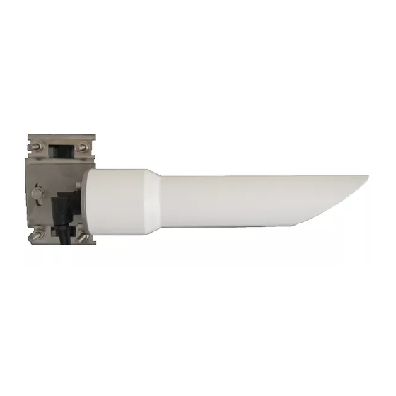
Page 8: Product Overview
The CS140 features a fixed 6˚ field of view as specified by the FAA. For easy installation, the CS140 is mounted horizontally with the required 6˚ inclination built into the design. (Other angles are possible via the sensors mounting bracket.) -
Page 9: Optical Specifications
8 bits, no parity, 1 stop bit (default) Supported data rates: 1200 baud 38400 baud (default) 2400 baud 57600 baud 9600 baud 115200 baud 19200 baud Supported standards: RS-232 (full duplex, no hardware handshaking) RS-485 half duplex CS140 Background Luminance Sensor... -
Page 10: Environmental Specifications
Temperature ranges Operating: –25 to +60 °C Extended operating: –40 to +70 °C (only guaranteed if sensor has been tested and verified by Campbell Scientific to operate over this range) Storage: –40 to +85 °C Sensor heater thresholds Dew heater turn on: <35°C... -
Page 11: Mechanical Specifications
Accuracy: ±6% Ingress protection: IP52 Communication: RS-232, 38400 baud (connecting the calibrator to the CS140 forces communications to RS-232, 38400 baud, and the sensor ID to 0.) Dimensions (excluding cables): 7.2 cm (2.8 in) long, 4.6 cm (1.8 in) diameter Weight: 300 g (10.5 oz) -
Page 12: Installation
6°. 4.2 Grounding The CS140 must be properly grounded with a ground wire that has a minimum cross sectional area of 6 mm and maximum length of 5 m from the brass grounding lug at the rear of the unit to an adequate grounding point. -
Page 13: Mounting
(p. 7) are used to level the CS140. Screw A is used to lock the CS140 at the right elevation with screw B acting as a pivot. Usually, this will be with the hood horizontal which gives a field of view elevated by 6°. -
Page 14: Connectors
4.4 Connectors The CS140 has two connectors. One connector supports communications and supplies power to the sensor. The other connector provides power to the hood heater. Figure 4-2. Connector layout Figure 4-3 (p. 8) shows the pin-outs of the sockets viewed from outside. Colours shown are the colours of the cores in the supplied cables. -
Page 15: Wiring Using Supplied Campbell Scientific Cables
Campbell Scientific offers a maintenance cable that will force communications to RS-232, 38400 baud, and sensor id to 0. The cable connectors allow it to be put in between the CS140 and the existing connection and a 5 m flying lead with a 9-way D connector for RS-232 communication. -
Page 16: Storage Information
ID will return to those previously set. Figure 4-5. Maintenance cable 4.7 Storage information The CS140 should be stored between –40 to 85 °C in a dry place. The optics should be protected from possible accidental damage. 5. Message structure... - Page 17 Full format. Contains all system alarms codes System status break down reflects the highest level of severity of any active alarm. Refer to the individual alarms (below) for details of the response times of the alarms. CS140 Background Luminance Sensor...
- Page 18 0 to 3 below 10%. contaminated 1 or 2 = Reported dirt level is over 10% 3 = High level of returned dirty signal. This could be either a blocked sensor or a broken dirty window system. CS140 Background Luminance Sensor...
- Page 19 The amount of background light as Detector DC seen by the detector hood. saturation level 0 = Within limits 1 = Saturated. The CS140 is experiencing direct light levels that are saturating the photo diode 0 = Signature of entire flash was Signature error...
-
Page 20: Interface Methods
6.5 Menu system 6.1 Command line menu The CS140 can be setup and controlled in one of two ways. The first method is by using the command line interface where discrete commands are sent without response from the sensor. This method is preferred for setting up a CS140 that is connected to a data logger. The data logger can send configuration setting commands to the CS140 removing the need for a computer to set up the unit. -
Page 21: Configuring Computer
After adjusting the baud rate of the unit, use the terminal emulator to adjust the bits per second value in the port settings. The CS140 can not communicate with the computer if the unit and port setting baud rates differ. - Page 22 5 = 2400 bps 6 = 1200 bps Serial number 0 to 32000 Internal serial number – (read only) Units for the CS140 luminance value: Luminance units 0 or 1 0 = Candela per metres square (cd/m 1 = Foot lamberts (fL)
- Page 23 Averaging period 1 or 10 The period of time that the luminance value should be averaged over. 0 = Allow the CS140 to automatically Dew heater override 0 or 1 control the dew heater 1 = Turn the dew heater off...
-
Page 24: Command Line Mode
The CS140 can be configured to expect any commands sent to it to include a valid checksum. For simple commands such as GET and POLL, fixed value checksums can be used. For more complex SET commands the checksum needs to be calculated. -
Page 25: Set Command
6.4.1 SET command The SET command is used to configure the CS140 using the command line. The SET command is a single space delimited string that can be sent from any data logger or computer equipped with an RS-232 or RS-485 port. The SET command accesses identical settings within the CS140. This command is used to change the default power up state of the sensor. -
Page 26: Setnc Command
SETNC. The only functional difference is that the SETNC command does not commit the values set into flash memory. This means that the next time the CS140 is power cycled it will revert back to its previous settings. This command should be used when a setting in the sensor is changed regularly, e.g. - Page 27 0 0 2 1000 0 60 0 2 1 1 0 0 0 1 7.0 0 0 10000 626C Table 6-4: GET command returned data Example Description 0x02 Sensor ID Serial port protocol Serial baud rate 1000 Sensor serial number (read only) Luminance units Continuous mode output interval CS140 Background Luminance Sensor...
-
Page 28: Poll Command
6.4.4 Poll command The POLL command requests the current visibility and/or alarm conditions from the CS140. The output format of this command depends on how the CS140 is configured using the SET command or the menu interfaces. Example of a POLL request with returned message: POLL : 0 : 0 : 3 A3B: 2 0 0 60 22.9 1 1 0 0 0 0 0 0 0 0 0 0 0 0 0 5EC7... -
Page 29: Menu System
These values are shown in hexadecimal format not ASCII. 6.5 Menu system When connected to the CS140, the user can enter the menu system by typing open id in their terminal program then pressing the return key on their keyboard. The ID corresponds to the sensor ID number. - Page 30 No changes will take effect until you Exit and Save. The exception to this is the calibration menu, but you will be informed before any changes are made. Type 1 to open the message menu containing settings relating to the CS140 outputs. Menu 1: The message output menu:...
- Page 31 Menu 2: The user alarm menu: CS140 ALARM AND LIMIT MENU 2 ID 0 S/N 1009 (1) Toggle user alarm one: DISABLED (2) Toggle alarm one threshold: LESS THAN (3) Set new user alarm one activation point: 10000 cd/m (4) Set upper output limit: 45000 cd/m...
- Page 32 Cleaning (p. 33). If there is a flash error or signature error, contact Campbell Scientific. The aux supply voltages are internal 5 volt and 3 volt supplies. They should be between 4.5 and 5.5 and 2.7 and 3.3 volts respectively.
-
Page 33: Calibration
(9) Refresh (0) Return to main menu -> Menu option (6) allows calibration of the CS140 using an optional calibration device. It also allows the user to reset the CS140 to factory default values. CS140 CONFIGURATION MENU 6 ID 0... - Page 34 Select option 1 to start the calibration. At this point the calibration device and cable should be installed as shown in the following figures. Connecting the calibrator switches the CS140 to communication at 38400 baud with a sensor ID of 0. This will happen whatever the previous setting or whether the CS140 was set to RS-232 or RS-485.
- Page 35 Dark level test complete. This part of the test will take approximately two minutes. Every ten seconds a dot should appear indicating that the test is progressing as normal. The CS140 will then ask you to turn on the calibrator device.
-
Page 36: Os Update
Operating system updates for the CS140 background luminance sensor are performed using Campbell Scientific Device Configuration Utility software. This is available as a free download from the Campbell Scientific website. Please refer to the help built into the Device Configuration Utility for full instructions on how to update the CS140. - Page 37 Figure 8-1. CS140 Device Configuration Utility OS download instructions CS140 Background Luminance Sensor...
-
Page 38: Maintenance
9. Maintenance 9.1 General The CS140 is a robust weather resistant instrument and there is no need for routine maintenance other than cleaning. The instrument performance is monitored and any potential problems are covered by error messages. Other maintenance is carried out by return to Campbell Scientific. -
Page 39: Cleaning
This will vary depending on the site location. The CS140 is capable of self-diagnosing a dirty window and will indicate in its output when the window is contaminated. -
Page 40: Appendix A. Example C Code Of The Ccitt Crc
The following code is provided as an example for programmers implementing their own code to communicate with the sensor. Users using Campbell data loggers can use the checksum command in CRBasic Editor to generate a CCITT checksum. Refer to the downloadable example programs available at www.campbellsci.eu/downloads/cs140-program-examples. - Page 41 Campbell Scientific Regional Offices Australia France Thailand Location: Garbutt, QLD Australia Location: Vincennes, France Location: Bangkok, Thailand Phone: 61.7.4401.7700 Phone: 0033.0.1.56.45.15.20 Phone: 66.2.719.3399 Email: info@campbellsci.com.au Email: info@campbellsci.fr Email: info@campbellsci.asia Website: www.campbellsci.com.au Website: www.campbellsci.fr Website: www.campbellsci.asia Brazil Germany Location: São Paulo, SP Brazil...
Need help?
Do you have a question about the CS140 and is the answer not in the manual?
Questions and answers