
Related Manuals for Ametek Sorensen DCS M51 Series


Summary of Contents for Ametek Sorensen DCS M51 Series
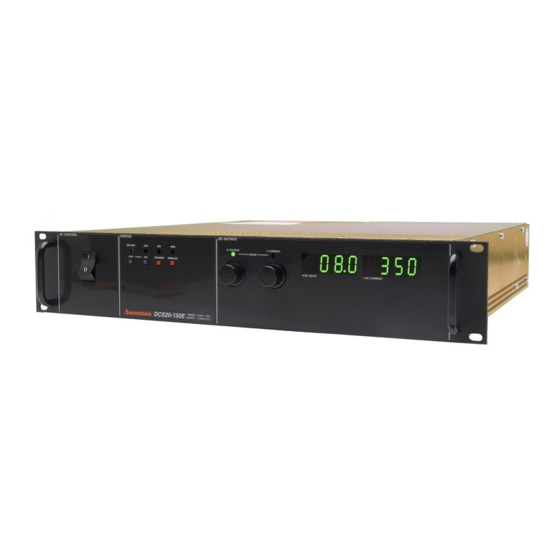
- Page 1 DCS Series M51 Isolated Analog Option Programming Manual M360002 Rev D www.programmablepower.com...
- Page 3 About AMETEK AMETEK Programmable Power, Inc., a Division of AMETEK, Inc., is a global leader in the design and manufacture of precision, programmable power supplies for R&D, test and measurement, process control, power bus simulation and power conditioning applications across diverse industrial segments.
- Page 4 This page intentionally left blank.
- Page 5 Neither AMETEK Programmable Power Inc., San Diego, California, USA, nor any of the subsidiary sales organizations can accept any responsibility for personnel, material or inconsequential injury, loss or damage that results from improper use of the equipment and accessories.
- Page 6 This page intentionally left blank.
-
Page 7: Table Of Contents
CONTENTS SECTION 1 DESCRIPTION AND SPECIFICATIONS......1-1 Introduction...................... 1-1 Specifications ....................1-1 SECTION 2 INSTALLATION AND OPERATING INSTRUCTIONS..2-1 Programming Connection................2-1 Programming Mode ..................2-1 Operation......................2-2 Calibration ....................... 2-2 SECTION 3 THEORY OF OPERATION..........3-1 General......................3-1 Isolation Amplifier .................... 3-1 Isolated Power Supply.................. - Page 8 M51 Isolated Analog Option DCS Series This page intentionally left blank. M360002 Rev D...
-
Page 9: Section 1 Description And Specifications
SECTION 1 DESCRIPTION AND SPECIFICATIONS Introduction The M51 isolated interface allows complete remote programming control of either the power supply output voltage or current using analog program signals, that may be biased at any potential relative to the power supply return line (within the maximum voltage differential specification). - Page 10 M51 Isolated Analog Option DCS Series This page intentionally left blank. M360002 Rev D...
-
Page 11: Section 2 Installation And Operating Instructions
SECTION 2 INSTALLATION AND OPERATING INSTRUCTIONS Programming Connection Connect the remote program signal line to the input connector (J1) as shown below. Check that signal polarity is correct (+ to J1 pin 7, – to J1 pin 6). Wiring for the program line should be either a twisted pair, or a shielded pair, with the shield tied to the power supply chassis. -
Page 12: Operation
M51 Isolated Analog Option DCS Series Operation After appropriate programming mode has been selected, and the external programming voltage source has been connected, the output of the power supply may be varied by adjusting the programming voltage. CAUTION! Never allow the power supply output voltage or current to exceed the rated maximum. -
Page 13: Section 3 Theory Of Operation
SECTION 3 THEORY OF OPERATION General The M51 interface board consists of two functional blocks, the isolation amplifier with input buffer amplifier and associated switching circuitry, and the isolated power supply, which provides power to the input side of the isolation amplifier. Isolation Amplifier The isolation amplifier U1, has a capacitively isolated input stage, which prevents any D.C. - Page 14 M51 Isolated Analog Option DCS Series 14 to approximately 2.5V, the same level as the internal reference in the PWM. The on time of Q1 is controlled to maintain this sensed voltage at 2.5V, which also keeps the main secondaries at pin 6, 7 and 8 regulated.
Need help?
Do you have a question about the Sorensen DCS M51 Series and is the answer not in the manual?
Questions and answers