Table of Contents
Advertisement
Quick Links
Advertisement
Table of Contents

Related Manuals for Kongskilde MULTIAIR FC 4000


Summary of Contents for Kongskilde MULTIAIR FC 4000
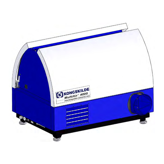
- Page 1 MULTIAIR FC 4000 High pressure blower Manual...
- Page 2 Blower doors Door release handle Operator panel Frequency converter Inlet Main switch Outlet Power supply relief Model plate Terminal block for connection of Intake panel equipment 1. Stop 2. Start 3. Setpoint down (decrease performance) 4. Setpoint up (increase performance)
-
Page 3: Warning Notes
The working area around the blower should be clear and trip free. Description: Make sure to have adequate lighting when working on The Kongskilde Multiair blower is designed for use with the blower. pneumatic conveying systems, but is also suitable for other industrial pneumatic solutions. -
Page 4: Warning Signs
-20 °C to 50 °C. Since it is much easier to main- tain a temperature above -20 °C in an external control cabinet, Kongskilde recommends using a MultiAir FCE 4000 blower with external control cabinet that can thus Always turn off the power to the blower... - Page 5 The blower doors are opened as follows: tions from the blower can propagate to the control The handles for opening the doors are located in each system. side of the doors. It is only necessary to press one han- The pipes on the blower's inlet and outlet side must be dle to open the doors.
- Page 6 1 - The main switch is switched off and locked 2 - The doors on both sides are opened The operator panel on the MultiAir FC 4000 is mounted and connected inside the blower on delivery, as shown: 3 - The cable ties on the operator panel wires are cut...
- Page 7 6 - the data cable is disconnected from the frequency 4 - the sealing strip on the end plate is pulled aside, converter - shown here on the V20 converter and the blind plug is removed 7 - the relief is loosened. The operator panel is un- hooked from the control, and hung upon the end plate as shown.
- Page 8 8 - The hoses from the aperture (at flow control) or control unit must be connected to the blower´s control. Kongskilde recommends to utilize Kongskildes stand- pressure outlet (at pressure control) are connected ac- ard pressure/vacuum- or flow control device for auto- cording to the illustration.
- Page 9 Connection of pressure/vacuum- or flow control Differential pressure transmitter for pressure/vacuum- or flow control Terminal block on the blower´s left side (seen from intake side) +24 V DC 500 Ω Connection of hose between Connection of hose between pressure transmitter and flow pressure transmitter and pres- measuring rod (for flow regu- sure gauge (for pressure/...
- Page 10 External start / stop contact External motor control Part no. Type Part no. Type External motor control 0,55kW (at 400V) 1,3-1,7A 100 503 357 External start / stop contact 100 503 338 100 503 345 External motor control 0,75kW (at 400V)1,7-2,3A 100 503 341 External motor control 1,1kW (at 400V) 2,3-3,1A 100 503 342...
- Page 11 If the external motor is overload- ed, the thermal relay will switch off and must be recon- nected after the fault has been investigated. Kongskilde recommends that the blue RESET button be set to position M (manual). If the button is placed in position A...
-
Page 12: Electrical Installation
Electrical installation: The Multiair blower is delivered in version for 3 x 380- 480V 50/60Hz voltage. All local factory inspectorate regulations must be com- plied with. Check that the on site electricity supply is suitable for the Multiair blower. See also the separate instructions for the MultiAir FC blower´s electrical equipment, that is supplied with the blower. - Page 13 In case the operator is not allowed to adjust the set- Setup of blower prior to operation point, the buttons Local and Remote will not appear. via the operator panel: In case user Tech has chosen Local access, the opera- After installation and electrical connection, the blower tor can also start and stop the blower, and adjust the can be setup to desired mode of operation.
-
Page 14: Fault Menu
MAIN DISPLAY Setpoint Blower model Fault menu Software version Current operating Settings menu point Colour indication showing operating status Remote / local mode Setpoint preset Stop Start Performance down Performance up The main display is accessible to all users and does not contain any language-dependent texts. Fault menu If an error occurs, the icon changes from black to flashing red. -
Page 15: Operating Status
In case the operator has no rights to switch between remote and local, the symbol does not appear. Version FC4000 FC4000: Specifies the blower model. Kongskilde delivers a complete parameter list for the various blower mod- Ver. 2.0 els, approx. 30 different blowers. Ver 2.0: Indicates software version. Operating status The screen shown here is the current operating status of the blower. - Page 16 The screen shown here is the current operating status of the blower. 1. 3800 - indicates the set point, in m 2. 3005 - indicates the current airflow of the blower, in m 3. Green blower icon - indicates that the blower is running. In this situation, the setpoint is set too high, or the blower performance too low.
- Page 17 Settings - User Tech User Tech is password protected. When the user is logged in as Tech, the screen appears with a light blue border. Operator rights to operate the blower can be adjusted with the following submenus. It is Tech´s task to grant the operator the necessary rights to operate the blower.
- Page 18 The 4 operating modes are described here: 1 - The blower is running at a fixed speed. Since the frequency converter in this operating mode keeps the blower speed constant, the PID control of the converter is not used. The blower speed unit is only rpm, so it is not possible to select other units.
- Page 19 Pressing the icon Wire diagram, a diagram appears, showing the connec- tion of a pressure- or flow transducer. When controlling pressure, flow or air speed, it is possible to choose a dif- ferent type of differential pressure transducer than the one supplied in the standard kit from Kongskilde.
- Page 20 The icon gives access to setpoint setup The screen on the left shows that only one setpoint has been selected, since setpoints 2 and 3 are crossed over. The setpoint is adjusted from either the up and down arrows on the operator panel, or via the digital inputs on the PLC (shown in the box in the upper right corner).
- Page 21 The icon shows status for digital input and output The icon gives access to a status image. It is not possible to manually ad- just the status of the digital inputs and outputs. The screen on the left shows the status screen for the blower setup, where 1 setpoint is selected.
- Page 22 Below are examples of connection diagrams: 0 – 10 V setpoint +24 V DC 0 V DC Signal 0 – 10 V 4 – 20 mA setpoint 500 Ω Signal 4 – 20 mA...
-
Page 23: Digital Output
0 – 10 V feedback +24 V DC 0 V DC Pressure / flow transmitter Signal 0 – 10 V 4 – 20 mA feedback +24 V DC 0 V DC Pressure / flow transmitter 500 Ω Signal 4 – 20 mA +24 V DC Digital in 0 Digital in 1... - Page 24 If the frequency converter has been replaced, proceed as follows: • login as Admin • press the Kongskilde logo in the upper right corner for 10 sec The Kongskilde logo changes to LOAD MOTOR DATA and flashes • press the flashing LOAD MOTOR DATA •...
-
Page 25: Operation
MultiAir 4000: The blower is switched on and off on the main switch. Service and maintenance: MultiAir FC 4000: All service, maintenance and repair must be performed The blower is switched on and off on the main switch. by qualified or instructed person. - Page 26 Always turn off the power to the blower before the in- spection, and be sure to lock the main switch, so that the blower cannot be started by mistake. Remove pip- ing on inlet and outlet side of the blower housing, so that a thorough overhaul of the rotor and blower hous- ing can be made.
-
Page 27: Troubleshooting
Troubleshooting: Fault Cause Remedy No power on the operator panel Missing main power supply or Check that the main power supply is con- switched off main switch (at the nected and that the main switch is on. blowers end plate). Interrupted circuit breaker at the Reconnect the circuit breaker (see sec- blowers frequency converter... - Page 28 If possible, reduce ambient temperature. If possible, reduce the need for capacity. Move the transducer to a vibration-free The differential pressure transducer surface is mounted on a vibrating surface. In case of doubt, contact a qualified service technician or Kongskilde service department.
- Page 29 Capacity Capacity Technical data: MultiAir® FC 4000 P MultiAir® FC 4000 P Performance curves for MultiAir FC 4000 P 20,000 20,000 MultiAir FC 4550 P 18,000 MultiAir FC 4550 P MultiAir FC 4450 P 18,000 MultiAir FC 4450 P MultiAir FC 4370 P...
- Page 30 MultiAir type FC 4220P FC 4300P FC 4370P FC 4450P FC 4550P Frequency converter output max. (kW) Nominal motor power (kW) Power supply 380 - 480 V, 50 or 60 Hz Min. fuse rating (Ampere) Max. fuse rating (Ampere) Weight (kg) 1.032 1.040 1.054...
- Page 31 The MultiAir FC 4000P series meets the European Ecovent 2009/125 / EC requirements according to the Commission Regulation (EC) no. 327/2011. On the blower, this is documented via the marking as prescribed (example): The label indicates the required values according to the standard.
-
Page 32: Ec Declaration Of Conformity
EC Declaration of Conformity Kongskilde Industries A/S, DK-4180 Sorø - Denmark, hereby declares that: Kongskilde blowers type MultiAir FC 4000 series Are produced in conformity with the following EC-directives and regulations: • Machinery Directive 2006/42/EC • Electro Magnetic Compatibility Directive 2014/30/EC •... - Page 33 123 040 902 You can always find the latest version of the manuals at 25.01.2021 www.kongskilde-industries.com Kongskilde Industries A/S Skælskørvej 64 DK - 4180 Sorø Tel. +45 72 17 60 00 mail@kongskilde-industries.com www.kongskilde-industries.com...
Need help?
Do you have a question about the MULTIAIR FC 4000 and is the answer not in the manual?
Questions and answers