Table of Contents
Advertisement
Quick Links
Advertisement
Table of Contents

Related Manuals for Vollrath Stoelting U218


Summary of Contents for Vollrath Stoelting U218
- Page 1 Model U218 OPERATORS MANUAL Manual No. 513631 Rev.1...
- Page 3 This manual provides basic information about the machine. Instructions and suggestions are given covering its operation and care. The illustrations and specifi cations are not binding in detail. We reserve the right to make changes to the machine without notice, and without incurring any obligation to modify or pro- vide new parts for machines built prior to date of change.
- Page 4 A Few Words About Safety Safety Information Safety Alert Symbol: Read and understand the entire manual before This symbol Indicates danger, warning or caution. operating or maintaining Stoelting equipment. Attention is required in order to avoid serious per- sonal injury. The message that follows the symbol This manual provides the operator with information contains important information about safety.
-
Page 5: Table Of Contents
TABLE OF CONTENTS Section Description Page Description and Specifications Description ....................1 Specifications ..................... 1 Installation Instructions Safety Precautions ..................3 Shipment and Transit ................. 3 Freezer Installation ..................3 Initial Set-Up and Operation Operator”s Safety Precautions ..............5 Operating Controls and Indicators ............. 5 Sanitizing .................... -
Page 7: Description And Specifications
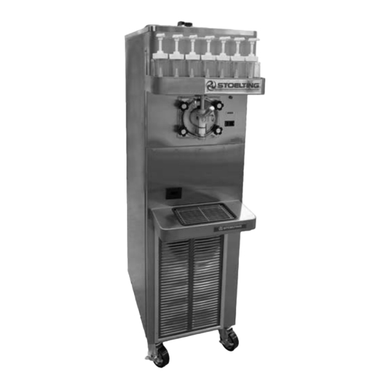
SECTION 1 DESCRIPTION AND SPECIFICATIONS 1.1 DESCRIPTION The Stoelting U218 freezer is available as gravity fed or with an optional autofill kit. It is equipped with fully auto- matic controls to provide a uniform product. The U218 freezer will operate with almost any type of frozen bever- age mix. - Page 8 1.2 SPECIFICATIONS - CONTINUED Model U218 Dimensions Freezer with crate 18-1/4'' (46,3 cm) 25'' (63,5 cm) width 64-1/2'' (163,8 cm) 66'' (167,5 cm) height 33'' (83,7 cm) 51'' (129,5 cm) depth 1 lbs (0,5 kg) 1 lbs (0,5 kg) Weight Electrical 1 Phase, 208-230 VAC, 60Hz approximately 12A...
-
Page 9: Installation Instructions
SECTION 2 INSTALLATION INSTRUCTIONS 2.1 SAFETY PRECAUTIONS Do not attempt to operate the freezer until the safety precautions and operating instructions in this manual are read completely and are thoroughly understood. Take notice of all warning labels on the freezer. The labels have been put there to help maintain a safe working environment. -
Page 11: Initial Set-Up And Operation
SECTION 3 INITIAL SET-UP AND OPERATION 3.1 OPERATOR’S SAFETY PRECAUTIONS 3.2 OPERATING CONTROLS AND INDICATORS SAFE OPERATION IS NO ACCIDENT; observe these Before operating the freezer, it is required that the operator rules: know the function of each operating control. Refer to Figure 3-1 for the location of the operating controls on the Know the freezer. -
Page 12: Sanitizing
system. When the switch is in the ON position, the When sanitizing the freezer, refer to local sanitary regula- freezer will operate in the freezing mode. When tions for applicable codes and recommended sanitizing the switch is in the CLEAN position, all refrigeration products and procedures. -
Page 13: Freeze Down And Operation
After five minutes, place a bucket under the spigot 3.6 CLEANING THE FREEZER and open spigot to drain most sanitizing solution. NOTE Leave a small amount of the sanitizing solution in The frequency of cleaning the freezer and freezer the freezing cylinder. Place the switch in the OFF parts must comply with local health regulations. -
Page 14: Cleaning The Freezer Parts
Figure 3-3 Remove Spigot Pin Remove the spigot handle. Remove front door by turning the circular knobs Figure 3-5 Remove O-Ring and then pulling door off the studs. NOTE Remove auger assembly from the freezing cylinder When removing front door, entire door and stator and remove auger blades. -
Page 15: Assembly Of Freezer
CAUTION Do not allow sanitizer to remain in contact with stain- less steel freezer parts for prolonged periods. Pro- longed contact of sanitizer with freezer may cause corrosion of stainless steel parts. 3.10 ASSEMBLY OF FREEZER To assemble the freezer parts, refer to the following steps: NOTE Petrol Gel sanitary lubricant or equivalent must be Figure 3-6 Brush Freezing Cylinder... -
Page 16: Routine Cleaning
3.11 ROUTINE CLEANING To remove spilled or dried mix from the freezer exterior, wash in the direction of the finish with warm soapy water and wipe dry. Do not use highly abrasive materials as they will mar the finish. 3.12 PREVENTIVE MAINTENANCE DAILY The exterior should be kept clean at all times to preserve the luster of the stainless steel. -
Page 17: Extended Storage
If the condenser is dirty, place a wet towel over the front (outside) of the condenser. Using a vacuum, carefully clean the condenser coil from the inside and outside of the freezer. A stiff bristled brush may help in releasing debris from between the condenser coils. -
Page 19: Troubleshooting
SECTION 4 TROUBLESHOOTING 4.1 LIGHT INDICATORS The freezer has two lights that will alert the user if a problem occurs: an ADD MIX light and a Diagnostic Light. The ADD MIX light will flash to alert the operator to a low mix condition. It does so by monitoring the mix level in the hopper. - Page 20 4.2 TROUBLESHOOTING - CONTINUED PROBLEM POSSIBLE CAUSE REMEDY 1. No vent space for free flow of cooling 1. A minimum of 3" of vent space required. (See air. Section 2) 2. Air temperature entering condenser is 2. Change location or direct hot air away from above 100°F.
-
Page 21: Replacement Parts
SECTION 5 REPLACEMENT PARTS 5.1 DECALS AND LUBRICATION Part Description Quantity 208135 Brush - 4" X 8" X 16" (Barrel) 208380 Brush - 1/4" X 3" X 14" 208401 Brush - 1" X 3" X 10" 324105 Decal - Caution Electrical Shock 324106 Decal - Caution Electrical Wiring Materials 324107... -
Page 22: Auger Shaft And Faceplate Parts
5.2 AUGER SHAFT AND FACEPLATE PARTS... - Page 23 5.2 AUGER SHAFT AND FACEPLATE PARTS - CONTINUED...
-
Page 24: Hopper Parts
5.3 HOPPER PARTS 314465 600082 695706 194024 417010 744281 744287 Part Description Quantity 194024 Bottle - Flavor 314465 Cover - Hopper 417010 Grid - Drip Tray 600082 Pump - Flavor 624607-5 O-Ring - Mix Inlet (5 Pack) 695706 Spring - Consistency Adjustment (Green) 744287 Tray - Drip 744281... -
Page 25: Autofill Options
5.4 AUTOFILL OPTIONS The E112 and F112 freezers can easily be configured to use an Autofill System. The Autofill System provides a constant supply of non-dairy mix to the freezer. AUTOFILL KIT An autofill kit is needed to use an Autofill System. The kit includes a solenoid, tubing, and a new hopper cover (the F112 also includes a transformer). - Page 27 WARRANTY MIX TRANSFER PUMPS / COCKTAIL / SLUSH 1. Scope: Stoelting LLC warrants to the first user (the “Buyer”) that the evaporator assembly and compressor (if applicable) of Stoelting mix transfer pump, cocktail and slush equipment will be free from defects in materials and workmanship under normal use and proper maintenance appearing within five (5) years (two (2) years for “Mirage”...
Need help?
Do you have a question about the Stoelting U218 and is the answer not in the manual?
Questions and answers