Table of Contents
Advertisement
Quick Links
Advertisement
Table of Contents
Troubleshooting

Subscribe to Our Youtube Channel
Related Manuals for Vollrath Stoelting U431


Summary of Contents for Vollrath Stoelting U431
- Page 1 Model U431 SERVICE MANUAL Manual No. 513572 Rev.5...
- Page 3 This manual provides basic information about the machine. Instructions and suggestions are given covering its operation and care. The illustrations and specifi cations are not binding in detail. We reserve the right to make changes to the machine without notice, and without incurring any obligation to modify or pro- vide new parts for machines built prior to date of change.
- Page 4 A Few Words About Safety Safety Information Safety Alert Symbol: Read and understand the entire manual before This symbol Indicates danger, warning or caution. operating or maintaining Stoelting equipment. Attention is required in order to avoid serious per- sonal injury. The message that follows the symbol This manual provides the operator with information contains important information about safety.
-
Page 5: Table Of Contents
TABLE OF CONTENTS Sect. 1 INTRODUCTION ..................1 Description ....................1 Specifications ..................1 Sect. 2 INSTALLATION INSTRUCTIONS ............3 Safety Precautions .................. 3 Shipment & Transit .................. 4 Freezer Installation ................... 4 Installing Permanent Wiring ..............4 Mix Pump (Serial #0 thru 17977) .............. 5 Mix Pump (Serial #17978 and up) ............ - Page 6 TABLE OF CONTENTS Sect. 5 REFRIGERATION SYSTEM ..............31 Refrigeration System ................31 Compressor .................... 31 Condenser ....................32 Evaporator ....................32 Cab Unit ....................34 Sect. 6 ELECTRICAL CONTROL SYSTEM ............35 Control System ..................35 Current Sensor ..................36 Contactors ....................
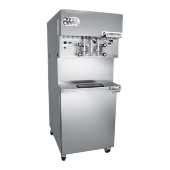
- Page 7 ILLUSTRATIONS Figure 1 Model U431 Freezer .............. 1 Figure 2 Specifications ................ 1 Figure 3 Decal Label Locations ............3 Figure 4 Water/Electrical Connections ..........4 Figure 5 Auger Rotation ............... 4 Figure 6 Mix Hose Installation............... 5 Figure 7 Mix Pump ................6 Figure 8 4 Way Tee ................
- Page 8 ILLUSTRATIONS Figure 33 Potentiometer ................ 23 Figure 34 Overrun Adjustment ..............23 Figure 35 Pump Roller Assembly ............24 Figure 36 Temperature Control Cab ............25 Figure 37 Belt Adjustment ..............25 Figure 38 Nameplate ................31 Figure 39 Terminal Cover Removal ............31 Figure 40 Compressor Connections ............31 Figure 41 Expansion Valve ..............
-
Page 9: Section 1 Introduction
SECTION 1 INTRODUCTION 1.1 DESCRIPTION The Stoelting U431 floor model freezer is pressure fed. The freezer is equipped with fully automatic controls to provide a uniform product. The freezer is designed to op- erate with almost any type of commercial soft-serve or non-dairy mixes available, including ice milk, ice cream, yogurt, and frozen dietary desserts. -
Page 11: Section 2 Installation Instructions
SECTION 2 INSTALLATION INSTRUCTIONS 2.1 SAFETY PRECAUTIONS periodically to be sure they have not been painted over, rubbed off, fallen off, and can be recognized as warning Do not attempt to operate the freezer until the safety pre- labels. cautions and operating instructions in the manual are read If you are in need of replacement labels, indicate the part completely and are thoroughly understood. -
Page 12: Shipment & Transit
2.2 SHIPMENT AND TRANSIT The freezer has been assembled, operated, and inspected at the factory. Upon arrival at the final destination, the freezer must be checked for any damage which may have occurred during final transit. With the method of packaging used, the equipment should arrive in excellent condition. -
Page 13: Mix Pump (Serial #0 Thru 17977)
2.5 MIX PUMP (Serial #0 thru 17977) Mix Pump Hose Installation Follow the steps below to install the mix pump hose. 1. Turn pump on. 2. Feed one end of mix pump hose into the entering or pick-up hose side (left) of black cover. 3. -
Page 14: Figure 7 Mix Pump
Connect 1/2 inch I.D. plastic food grade tubing to check valve and then to the mix container. Observe check valve flow arrow. Secure with hose clamps. Then place assembly thru hole in cover and install retainer clip. Figure 9. Connect 1/2 inch I.D. plastic food grade tubing between the large port of air/mix tee and refrigeratedmix transfer line. -
Page 15: Figure 8 4 Way Tee
Refrigerated Mix Transfer Line 4 Way Tee Large Port Air/Mix Tee Figure 8. 4 Way Tee Low Mix Cord Cover Retainer Clip Container Figure 9. Mix Inlet Tube & Probe Assy. Clip Hose Holder Figure 10. Hose Holder... -
Page 16: Mix Pump (Serial #17978 And Up)
2.6 MIX PUMP (Serial #17978 and Up) Mix Pump Hose Installation Follow the steps below to install the mix pump hose. 1. Turn pump on. 2. Feed one end of mix pump hose into the entering or pick-up hose side (left) of black cover. 3. -
Page 17: Figure 12 Mix Pump
Connect 1/2 inch (12,7mm) I.D. plastic food grade tubing to mix check valve (Item 7) and then to the mix container. Observe check valve flow arrow. Secure with hose clamps. Then place assembly thru hole in cover and install retainer clip. See Figure 9. -
Page 18: Figure 13 3 Way Tee
Refrigerated Mix Transfer Line 3-way Tee Large Port (Air/Mix) Figure 13. 3-way Tee Low Mix Cord Cover Retainer Clip Container Figure 14. Mix Inlet Tube & Probe Assy. Clip Hose Holder Figure 15. Hose Holder... -
Page 19: Section 3 Initial Set-Up And Operation
SECTION 3 INITIAL SET-UP AND OPERATION Spigot Switch 3.1 SAFETY PRECAUTIONS When the spigot handle is opened the SPIGOT SAFE OPERATION IS NO ACCIDENT; observe these switch will start the auger drive and refrigeration rules: systems. When the spigot handle is closed, the drive Know the freezer. - Page 20 Dispense Rate Adjusters The dispense rate adjuster limits the opening of the spigot. To adjust product dispense rate, turn the adjusting knob clockwise for slower flow and counter- clockwise for faster flow. High Head Pressure Cut Out If the head pressure exceeds 445 PSIG (28 bar) air cooled and water cooled, the high head pressure cutout will trip.
-
Page 21: Important Information Regarding Cleaning And Sanitizing
3.3 IMPORTANT INFORMATION REGARDING CLEANING · Is the removal of soil materials from a surface. CLEANING AND SANITIZING · Is a prerequisite for effective sanitizing. Soft serve and shake freezers require special consideration when it comes to food safety and proper cleaning and sanitizing. -
Page 22: Disassembly Of Freezer Parts
The ideal concentration of chlorine needs to be 100 As a recommended cleaner and sanitizer for your ppm (as stated by the FDA). frozen dessert machine, STERA-SHEEN has proven to be one of the best daily maintenance products for: NOTE Follow the directions on the container for proper ·... -
Page 23: Cleaning Disassembled Parts
Disassembly Of Front Door 1. Remove the front door by turning off the circular knobs and then pulling the front door off the studs. 2. Remove the air bleed valve by unscrewing the knob while holding the valve stem from behind. Remove the compression spring and push air bleed valve through the rear of the front door. -
Page 24: Cleaning The Freezer
3.7 CLEANING THE FREEZER CAUTION Lubricate with Risk of Product Damage Socket Do not use acid cleaners, strong caustic compounds Lubricant or abrasive materials to clean any part of the freezer exterior or plastic parts. Lubricate with Petrogel Figure 21. Rear Seal Lubrciation The exterior should be kept clean at all times to preserve the lustre of the stainless steel. -
Page 25: Figure 23 Front Door Assembly
Assemble O-rings onto the spigot dry, without lubrication. Then apply a thin film of sanitary lubricant to the outside of the O-rings and spigot bodies. Install the spigots through the bottom of the front door ( see Figure 18). Figure 23. Front Door Assembly Assemble the air bleed valve O-ring onto the air bleed valves. -
Page 26: Sanitizing
3.9 SANITIZING Let sanitizing solution fill the freezer barrel to air bleed Sanitizing must be done after the freezer is clean and just valve, then close the valve by pulling out to lock in before the freezer is filled with mix. Sanitizing the night place. -
Page 27: Mix Information
The freezer is designed to dispense the product at a reasonable draw rate. If the freezer is overdrawn, the result will be a soft product and air pops. If this should occur, allow the freezer to run for approximately 30 seconds before dispensing additional product. -
Page 28: Operation Of Mix Pump
3.12 OPERATION OF MIX PUMP The over-run adjustment is preset at the factory. If an The pump switch is located on the front of the freezer. adjustment becomes necessary, refer to Section 4. When the pump switch is placed in the ON position, the mix pump motor will be actuated to pump mix into the freezer NOTICE cylinder. -
Page 29: Figure 29 Removable Parts
NOTE 9. Sanitize assembled freezer as per instructions If the mix lines or air line is difficult to remove, soften outlined in Section 3.9). with a rag soaked in hot water. Hose connections may be sprayed with Haynes Sanitary Lubricant for ease of removal. -
Page 31: Section 4 Maintenance Instructions
SECTION 4 MAINTENANCE INSTRUCTIONS 4.1 FREEZER ADJUSTMENT The mix pump has been preset at the factory to produce a This section is intended to provide maintenance person- product with approximately 40% overrun. Because of nel with a general understanding of the freezer adjust- differences in mix formulation, temperatures and baro- ments. -
Page 32: Mix Pump Hose Reposition
F. Tighten the allen screw, then place the wrench back CAUTION in its clip. Replace the lower back panel and secure NEVER DISCONNECT HOSES FROM FREEZER with the four screws. Turn the mix pump power switch OR PUMP WITHOUT FIRST OPENING SPIGOT to the ON position. -
Page 33: Drive Belt Tension Adjustment
4.8 CONDENSER CLEANING (AIR-COOLED FREEZERS) The condenser requires periodic cleaning. To clean the condenser, refer to the following steps: NOTE Some freezers have a condenser filter, to clean re- move and wash in warm soapy water. Rinse in clean water and shake dry, taking care not to damage filter in any way. -
Page 34: Extended Storage
WARNING NEVER ATTEMPT TO REPAIR OR PERFORM MAINTENANCE ON FREEZER UNTIL ALL MAIN ELECTRICAL POWER HAS BEEN DISCON- NECTED. 4.10 EXTENDED STORAGE Refer to the following steps for winterizing the freezer or for storing the freezer over any long period of shutdown time. -
Page 35: Freezer Reference Photos
4.11 FREEZER REFERENCE PHOTOS LEFT SIDE RIGHT SIDE... - Page 36 REAR UPPER REAR LOWER...
-
Page 37: Overrun Adjustment
AIR COOLED TOP OVERRUN ADJUSTMENT... -
Page 39: Sect. 5 Refrigeration System
SECTION 5 REFRIGERATION SYSTEM 5.1 REFRIGERATION SYSTEM The refrigeration system is designed for efficient use with the refrigerant and charge shown on the nameplate. Figure 31. Figure 39. Terminal Cover Removal 3. Remove wires C, R, and S at compressor. Figure 33. -
Page 40: Condenser
NOTE 3. Connect the freezer to the electrical supply, start The compressor is equipped with an internal over- the refrigeration cycle and read the pressure. load protector. If the compressor is warm and ohm- meter readings indicate an open winding, allow up 4. -
Page 41: Figure 42 Expansion Valve Removal
11.Recharge system to nameplate specification. NOTE The T.X.V. bulb should ALWAYS be mounted on the horizontal line (opposite from the sensor), with the capillary end facing the flow of refrigerant. Good contact between the bulb and the suction line is necessary for proper operation of the valve. -
Page 42: Cab Unit
E. Water Valve Removal 7. Triple evacuate the system. Evacuate twice to 1500 microns of mercury, breaking the vacuum WARNING each time with dry nitrogen. Then evacuate to 500 DISCONNECT FREEZER FROM ELECTRICAL microns of mercury. SUPPLY BEFORE SERVICING. 8. Replace insulation. Assuming the necessary panels are removed, perform the following procedures for removing the water valve. -
Page 43: Sect. 6 Electrical Control System
SECTION 6 ELECTRICAL CONTROL SYSTEM 6.1 CONTROL SYSTEM To provide easier access to components inside or on the The control system is the "brain" of the freezer. To under- back side of the electrical box, remove the four phillips stand how to service the freezer, it is essential to under- head screws holding the box to the frame. -
Page 44: Current Sensor
b. If the standby-serve switch is in the "standby before checking the resistance in a sensor, always make position", then as the high relay low set point is certain the temperature in the sensor is dropping. When satisfied, the yellow light goes off; the green light troubleshooting a sensor, remove the blue wire from the illuminates. -
Page 45: Section 7 Major Component Removal And Installation
SECTION 7 MAJOR COMPONENT REMOVAL AND INSTALLATION 7.1 PREPARATION FOR COMPONENT REMOVAL 7.3 DRIVE MOTOR REMOVAL The procedures set forth in the section MUST be fol- 1. Remove the electrical wires from the motor. lowed completely and in the order in which they appear. 2. -
Page 46: Compressor Removal
3. Recover refrigerant charge and leave a port open to prevent pressure build-up during compressor removal. 4. Remove six inches of insulating tubing on the suction line going to the compressor and unsweat the suction and discharge line from the compressor. 5. -
Page 47: Gearbox Installation
2. Fasten the two bolts through the mounting bracket at the rear of the freezer. 3. Mount the pulley on the gear box shaft and align with the motor pulley, then tighten the allen head set screws. 4. Tighten the drive belts. Figure 49. Figure 54. -
Page 48: Final Assembly Of Freezer
7.10 FINAL ASSEMBLY OF FREEZER Upon completion of the removal and installation of any or all of the major components of the freezer, the panels can be replaced by performing the following procedures: 1. Position the back panels into place and install the Phillips head screws, tighten securely. -
Page 49: Section 8 Troubleshooting
SECTION 8 TROUBLESHOOTING 8.1 Troubleshooting - Freezer . f f k " , " t n i l a t l a t l e l l . y l f l l . y l . f f n i l a t l a t l . -
Page 52: Troubleshooting - Mix Pump
8.3 Troubleshooting - Mix Pump . f f a t l a t l . f l l a t . y l o l l . t n o l l . r i c t i y t i v i t c t i i t c... - Page 53 t ' n . y l y l l s l i . y l y l t t s i c t i e t I t i x t l e t i s p " " s t i s s ' r .
-
Page 54: Troubleshooting The Challenger Temperature Control And Sensor
8.4 TROUBLESHOOTING THE CHALLENGER TEMPERATURE CONTROL AND SENSOR • Verify voltage at terminals 1&2 on the The specifications given are for the circuit board. The voltage should be about circuit Board PN 296657 using the 24 volts AC. 1/8” x 1” stainless steel sensor with •... - Page 55 FIGURE 1 FIGURE 2...
- Page 56 FIGURE 3...
- Page 57 Supply 220V AC Control Circuit Volts at Terminals 1 and 2 = 24 volts AC Temp Control #296657 Challenger Series - Models U431, 237R/238R, 217/217R Volts DC at Control Terminal No. 8 & 2nd Suction Gas Solder Spot Temperature °F cycled off = 7.53V -5°F No Resistance,...
- Page 58 STOELTING - 64 SENSOR TEMP RESISTANCE VOLTS TEMP RESISTANCE VOLTS DEG.F OHMS DEG.F OHMS -17.00 8865.54 25.00 2811.54 -16.00 8608.83 26.00 2741.20 -15.00 8360.33 7.08*` 27.00 2672.89 -14.00 8119.89 28.00 2606.44 -13.00 7887.19 29.00 2541.91 -12.00 7661.88 30.00 2479.19 -11.00 7443.93 7.50* 31.00...
- Page 59 CALIBRATION SPECIFICATIONS CHALLENGER SOFT SERVE Sensor P/N 737011 ( Two Blue Wires) OHMS Cut-In Cut-Out “HI” Stage Sensor 1516 (50°F) 2269 (34°F) + External Pot +2000 +2000 = Calibration 3516 4269 “LO” Stage Sensor 2327 (33°F) 5420 ( 0°F) + External Pot +2000 +2000 = Calibration...
-
Page 61: Sect. 9 Replacement Parts Information
SECTION 9 REPLACEMENT PARTS INFORMATION FRONT DOOR PARTS Item Stoelting P/N Qty. Description Item Stoelting P/N Qty. Description 2177427 Door (Side ID Grooves) 109018 Actuator, Door Safety 2177072 38mm (1.5 inch) Spigot Ext. 3159696 Spigot, Outside 2177073 64mm (2.5 inch) Spigot Ext. 3158086 Spigot, Center 2177074... -
Page 63: Miscellaneous Parts
AUGER PARTS Drawing Part Index No. Number Qty. Description 2104552 Auger Front Support 149003 Front Bearing 381804 Plastic Flight 694255 Spring 4151178 Auger 624678 Rear Seal "O" Ring 1151859 Rear Seal Adaptor 667868 Rear Seal MISCELLANEOUS PARTS Description Part No. Haynes Spray (12 oz.) ---------------------------------- 508017 Petro-Gel Tube (4 oz.) ----------------------------------... - Page 64 Pump Assembly (Serial #0 - 17977) 1177816 Figure 7. Mix Pump...
- Page 65 Pump Assembly (Serial #17978 and up)
- Page 67 DECALS Qty. Part Number Description 324200 H.P. Manual Reset 324798 Clean-Off-Serve 324797 Standby/Serve 324800 Cab Off-On 324799 Pump Off On 324141 Caution, Haz. Rot. Blade - Front Panel 324509 Cleaning - Right Side 324014 Auger Rotation - Evap. Enclosure Rear 324686 Danger - Start Auto, on Evap.
-
Page 83: General Order Advice
GENERAL ORDER ADVICE Customer No.: ________________ Customer P.O. No.: ________________ Stoelting Order No.: ______________ Sold To: _____________________________________ Date: __________________________________________ ____________________________________________ Ship To: ________________________________________ ____________________________________________ _______________________________________________ ____________________________________________ _______________________________________________ Contact Name: _______________________________ _______________________________________________ Phone: ______________________________________ _______________________________________________ Fax #: ______________________________________ Terms of Payment: _______________________________ Requested Routing: ______________________________ Freight: Collect __________ Prepaid __________ Prepay &... - Page 85 GENERAL ORDER ADVICE Customer No.: ________________ Customer P.O. No.: ________________ Stoelting Order No.: ______________ Sold To: _____________________________________ Date: __________________________________________ ____________________________________________ Ship To: ________________________________________ ____________________________________________ _______________________________________________ ____________________________________________ _______________________________________________ Contact Name: _______________________________ _______________________________________________ Phone: ______________________________________ _______________________________________________ Fax #: ______________________________________ Terms of Payment: _______________________________ Requested Routing: ______________________________ Freight: Collect __________ Prepaid __________ Prepay &...
Need help?
Do you have a question about the Stoelting U431 and is the answer not in the manual?
Questions and answers