
Subscribe to Our Youtube Channel
Related Manuals for Leuze AMS 384i


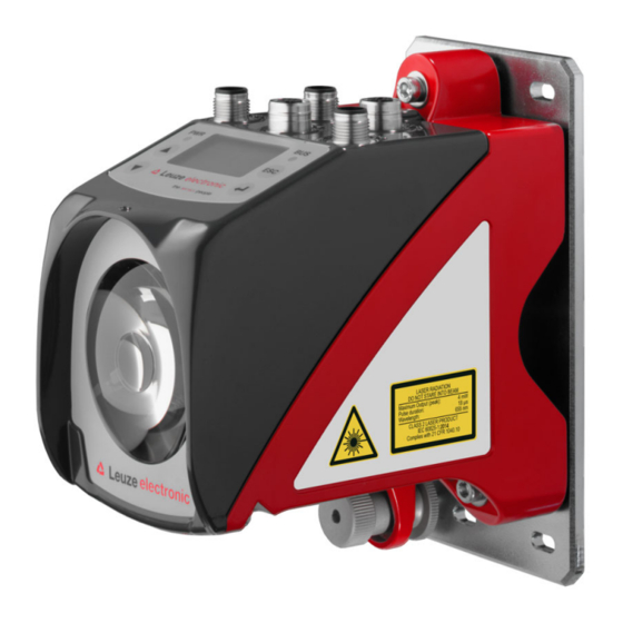
Summary of Contents for Leuze AMS 384i
- Page 1 Original operating instructions AMS 384i Optical laser measurement system – Interbus We reserve the right to make technical changes EN 2021/04/30 - 50113371...
- Page 2 © 2021 Leuze electronic GmbH + Co. KG In der Braike 1 D-73277 Owen / Germany Phone: +49 7021 573-0 Fax: +49 7021 573-199 http://www.leuze.com info@leuze.de Leuze electronic GmbH + Co. KG AMS 384...
- Page 3 AMS 384 The main menus Device information - main menu AMS 384i 120 Leuze electronic This menu item contains detailed informa- tion on GmbH & Co. KG • Device type SW: V 1.3.0HW:1 • Manufacturer SN: ----------------------- • Software and hardware version •...
-
Page 4: Table Of Contents
Table of contents General information ..........4 Explanation of symbols . - Page 5 Table of contents Reflectors ........... . . 26 General information .
- Page 6 Table of contents Interbus shield and grounding concept ........52 9.3.1 Interbus - Voltage supply electrical connection.
-
Page 7: General Information
Note! The Declaration of Conformity for these devices can be requested from the manufacturer. The manufacturer of the product, Leuze electronic GmbH & Co. KG in D-73277 Owen, possesses a certified quality assurance system in accordance with ISO 9001. AMS 384... -
Page 8: Description Of Functions Ams 384
With its AMS 3xx product series, Leuze makes available a wide range of internationally rele- vant interfaces. Note that each interface version listed below corresponds to a different AMS 3xx model. -
Page 9: Safety
Leuze electronic GmbH + Co. KG is not liable for damages caused by improper use. Read the technical description before commissioning the device. Knowledge of this ... -
Page 10: Competent Persons
Exemption of liability Leuze electronic GmbH + Co. KG is not liable in the following cases: • The device is not being used properly. • Reasonably foreseeable misuse is not taken into account. -
Page 11: Laser Safety Notices
The device must not be tampered with and must not be changed in any way. There are no user-serviceable parts inside the device. Repairs must only be performed by Leuze electronic GmbH + Co. KG. NOTE Affix laser information and warning signs! Laser information and warning signs are attached to the device (see figure 2.1). - Page 12 Safety A Laser aperture B Laser warning sign C Laser information sign with laser parameters Figure 2.1: Laser apertures, laser warning signs Leuze electronic GmbH + Co. KG AMS 384...
- Page 13 18 μs 18 μs Wavelength: 655 nm 655 nm CLASS 2 LASER PRODUCT IEC 60825-1:2014 Complies with 21 CFR 1040.10 IEC 60825-1:2014 Figure 2.2: Laser warning and information signs – supplied stick-on labels AMS 384 Leuze electronic GmbH + Co. KG...
-
Page 14: Fast Commissioning / Operating Principle
Fast commissioning / operating principle Fast commissioning / operating principle Note! Below you will find a short description for the initial commissioning of the AMS 384i. Detailed explanations for the listed points can be found throughout the handbook. Mounting the AMS 384... -
Page 15: Connecting The Voltage Supply
, which is stored in the control. The AMS 384 is connected via the BUS IN M12 connection or, in the case of a continuing network, via BUS OUT. Detailed information can be found in Chapter 9. AMS 384 Leuze electronic GmbH + Co. KG... -
Page 16: Technical Data
500kbit/s / 2Mbit/s Controls and indicators Keyboard 4 keys Display Monochromatic graphical display, 128 x 64 pixels 2 LEDs, two-colored Inputs/outputs Quantity 2, programmable Input Protected against polarity reversal Output Max. 60 mA, short-circuit-proof Leuze electronic GmbH + Co. KG AMS 384... - Page 17 This is a Class A product. In a domestic environment this product may cause radio interference, in which case the operator may be required to take adequate measures. The AMS 384 is designed in accordance with protection class III for supply with PELV (protective extra-low voltage). AMS 384 Leuze electronic GmbH + Co. KG...
-
Page 18: Ams 384 Dimensioned Drawing
M5 screw for alignment Knurled nut with WAF4 hexagon socket and M5 nut for securing Optical axis Zero point of the distance to be measured Figure 4.1: AMS 384 dimensioned drawing Leuze electronic GmbH + Co. KG AMS 384... -
Page 19: Overview Of Ams 384 I Types
50113738 AMS 384 200 H 200m operating range, Interbus interface, integrated heating 50113739 AMS 384 300 H 300m operating range, Interbus interface, integrated heating 50113740 Table 4.1: Overview of AMS 384 types AMS 384 Leuze electronic GmbH + Co. KG... -
Page 20: Installation And Mounting
Note! Please note that the shown name plate is for illustration purposes only; the contents do not correspond to the original. Save the original packaging for later storage or shipping. Leuze electronic GmbH + Co. KG AMS 384... -
Page 21: Mounting The Ams 384 I
AMS 384 and the reflector. Use M5 screws to fasten the laser measurement system. Secure the screws with a lock washer to protect against loosening caused by vibrations. AMS 384 Leuze electronic GmbH + Co. KG... - Page 22 ). Knurled nut and nut must not be tightened until alignment Figure 5.2 has been completed. Attention! The device must not be opened. Failure to comply will render the guarantee void. Warranted features cannot be guaranteed after the device has been opened. Leuze electronic GmbH + Co. KG AMS 384...
-
Page 23: Optional Mounting Bracket
A mounting bracket for mounting the AMS 384 on a flat, horizontal surface is available as an optional accessory. Type designation: MW OMS/AMS 01 Part no.: 50107255 Laser beam Figure 5.3: Optional mounting bracket AMS 384 Leuze electronic GmbH + Co. KG... -
Page 24: Parallel Mounting Of The Ams 384
Measurement distance up to 120m: minimum parallel spacing X ≥ 600mm Measurement distance up to 200m: minimum parallel spacing X ≥ 750mm Measurement distance up to 300m: minimum parallel spacing X ≥ 750mm Leuze electronic GmbH + Co. KG AMS 384... -
Page 25: Parallel Mounting Of Ams 384 I And Ddls Optical Data Transmission
Depending on the size of the used reflector, the DDLS can be mounted with a minimum parallel spacing of 100mm to the AMS 384 . The parallel spacing is independent of the distance. AMS 384 Leuze electronic GmbH + Co. KG... -
Page 26: Mounting The Ams 384 I With Laser Beam Deflector Unit
Use the M5 screws to mount the deflector unit. Secure the screws with a lock washer to protect against loosening caused by vibrations. Figure 5.5: Mounting variants of the US AMS 01 laser beam deflector unit Leuze electronic GmbH + Co. KG AMS 384... -
Page 27: Dimensioned Drawing Of Us Ams 01 Deflector Unit
Installation and mounting 5.3.2 Dimensioned drawing of US AMS 01 deflector unit Laser beam Figure 5.6: Dimensioned drawing of US AMS 01 deflector unit AMS 384 Leuze electronic GmbH + Co. KG... -
Page 28: Mounting The Us 1 Oms Deflector Unit Without Mounting Bracket
Height of the spring in non- preloaded state A Mirror Figure 5.7: Photo and dimensioned drawing of the US 1 OMS deflector unit The laser light spot is aligned with the reflector as described in Chapter 5.2. Leuze electronic GmbH + Co. KG AMS 384... -
Page 29: Reflectors
Reflectors General information The AMS 384 measures distances against a reflective tape specified by Leuze. All technical data given for the AMS 384 , such as the operating range or accuracy, can only be achieved with the reflective tape specified by Leuze. -
Page 30: Technical Data Of Self-Adhesive Tape
Do not use any abrasive agents. A conventional household detergent Cleaning can be used as a cleaning agent. Rinse with clear water and dry the surface. Reflector storage Store in a cool and dry place. Leuze electronic GmbH + Co. KG AMS 384... -
Page 31: Dimensioned Drawing Of Reflective Tape On Carrier Plate
Always align the TOP marking with the AMS connections! (Chapter Figure 6.1: Dimensioned drawing of reflectors Article Reflective tape (mm) Reflector plate (mm) Reflective tape 200x200-M Reflective tape 500x500-M Reflective tape 914x914-M AMS 384 Leuze electronic GmbH + Co. KG... -
Page 32: Technical Data Of Heated Reflectors
Do not use any abrasive agents. A conventional household Cleaning detergent can be used as a cleaning agent. Rinse with clear water and dry the surface. Reflector storage Store in a cool and dry place. Leuze electronic GmbH + Co. KG AMS 384... -
Page 33: Dimensioned Drawing Of Heated Reflectors
XL ± 1 Si cable 3 x 0.75mm² Figure 6.2: Dimensioned drawing of heated reflectors Article Reflective tape (mm) Insulated carrier plate (mm) Reflective tape 200x200-H Reflective tape 500x500-H Reflective tape 914x914-H AMS 384 Leuze electronic GmbH + Co. KG... -
Page 34: Selecting Reflector Size
The reflector sizes shown below are a recommendation from Leuze for on-vehicle mounting of the AMS 384i. For stationary mounting of the AMS 384i, a smaller reflector is generally sufficient for all measurement distances. For this reason, two smaller reflector sizes are avai lable in the self-adhesive variant "-S". -
Page 35: Mounting The Reflector
For this purpose, use the alignment elements provided on the AMS 384 … (see chapter 5.2 "Mounting the AMS 384i"). If necessary, remove the protective film from the reflector. Attention! The "TOP" label on the reflectors should be aligned the same as the connections of the... - Page 36 Direct reflection due to the triple structure Deflected surface reflection due to the pitch of the reflective tape Figure 6.3: Mounting the reflector Pitch approx. 1° Spacer sleeves Figure 6.4: Pitch of the reflector Leuze electronic GmbH + Co. KG AMS 384...
- Page 37 Direct reflection due to the triple structure Deflected surface reflection due to the pitch of the reflective tape Figure 6.5: Mounting of heated reflectors Pitch approx. 1° Spacer sleeves Figure 6.6: Pitch of the heated reflector AMS 384 Leuze electronic GmbH + Co. KG...
-
Page 38: Table Of Reflector Pitches
Reliable operation of the and, thus, max. operating range and accuracy can only AMS 384 be achieved with the reflective tape specified by Leuze. Correct operation cannot be guar anteed if other reflectors are used! Leuze electronic GmbH + Co. KG... -
Page 39: Electrical Connection
The laser measurement systems are designed in accordance with protection class III for sup ply by PELV (protective extra-low voltage with reliable disconnection). Note! Degree of protection IP65 is achieved only if the connectors and caps are screwed into place! AMS 384 Leuze electronic GmbH + Co. KG... -
Page 40: Pwr - Voltage Supply / Switching Input/Output
To the Interbus master DI 3 To the Interbus master, inverted Data Data GND Data Ground Shield via RC element on the hous- M12 connector Thread SHIELD (B-coded) Table 7.2: BUS IN pin assignment Leuze electronic GmbH + Co. KG AMS 384... -
Page 41: Interbus Bus Out
RS232-RX Receiving line RS 232/service data RS232-RX Not used M12 socket (A-coded) Thread Functional earth (housing) Table 7.4: Pin assignment - Service Note! The service interface is designed only for use by Leuze! AMS 384 Leuze electronic GmbH + Co. KG... -
Page 42: Display And Control Panel Ams 384I
Display and control panel AMS 384i Display and control panel AMS 384 Structure of the control panel Status indicator Bus/interface info Bar graph Distance measurement value Control buttons Figure 8.1: Structure of the control panel using the AMS 304 PROFIBUS device variant as... - Page 43 Display and control panel AMS 384i Warning - laser prefailure message: Laser diode old, device still functional, exchange or have repaired. Warning - temperature monitoring: Internal device temperature above/below permissible range. Plausibility error: Implausible measurement value. Possible causes: light beam interruption, outside of measurement range, permissible internal device temperature considerably exceeded or traverse rate >10m/s.
-
Page 44: Led Status Indicators
Display and control panel AMS 384i 8.2.2 LED status indicators PWR LED Device OFF - No supply voltage Flashing green Power LED flashes green - No measurement value output - Voltage connected - Self test running - Initialization running - Parameter download running... -
Page 45: Control Buttons
Display and control panel AMS 384i Green continuous light BUS LED green - Interbus interface ready for communication. 8.2.3 Control buttons Navigate upward/sideways. Down Navigate downward/sideways. Exit menu item. ENTER Confirm/enter value, change menu levels. Navigating within the menus The menus within a level are selected with the up/down buttons... -
Page 46: Menu Description
Display and control panel AMS 384i Menu description 8.3.1 The main menus After voltage has been applied to the laser, device information is displayed for several seconds. The display then shows the measurement window with all status information. Device information - main menu... -
Page 47: Parameter Menu
Display and control panel AMS 384i Note! The rear cover of this manual includes a fold-out page with the complete menu structure. It describes the menu items in brief. 8.3.2 Parameter menu Parameter handling submenu The following functions can be called up in the Parameter handling submenu: •... - Page 48 Display and control panel AMS 384i Tabelle 8.2: Interbus submenu Level 3 Level 4 Level 5 Selection/configuration option Standard Description Encoding Gray / binary Gray Specifies the output format of the measurement value. Position reso- 0.1mm / 1mm / 10mm / free resolution...
- Page 49 Display and control panel AMS 384i I/O submenu Table 8.4: I/O submenu Level 3 Level 4 Level 5 Selection/configuration option Standard Description I/O 1 Port con- Input/Output Output figuration Defines whether I/O 1 functions as an output or input. Switching...
- Page 50 Service Baud rate 57.6kbit/s / 115.2kbit/s 115.2kbit/ RS232 The service interface is only available to Leuze personnel. Format 8,e,1 / 8,n,1 8,n,1 The service interface is only available to Leuze personnel. Leuze electronic GmbH + Co. KG AMS 384...
-
Page 51: Language Selection Menu
Display and control panel AMS 384i 8.3.3 Language selection menu Language selection o Deutsch English o Español o Français o Italiano 5 display languages are available: • German • English • Spanish • French • Italian The AMS 384 is delivered from the factory with the display preset to English. -
Page 52: Operation
Display and control panel AMS 384i Operation An operating process is described here using parameter enable as an example. Parameter enable During normal operation parameters can be viewed only. If parameters are to be changed, the ON menu item in the Parameter -> Parameter handling -> Parameter enable menu must be activated. - Page 53 Display and control panel AMS 384i Password for parameter enable Parameter entry on the AMS 384 can be protected with a four-digit numerical password. On the AMS 384 , the password is entered via the display. If parameter enable has been acti- vated after successfully entering the password, parameters can be changed via the display.
-
Page 54: Interbus Interface
To the Interbus master, inverted inverted Data Data Data Ground Data Ground Thread SHIELD Shield via RC element on the Thread SHIELD Shield directly on the housing housing Figure 9.1: Interbus - Electrical connection Leuze electronic GmbH + Co. KG AMS 384... -
Page 55: Interbus Shield And Grounding Concept
Input/output 2, by default: Output: low (0 V) = Velocity limit value exceeded high (VIN) = Velocity limit value not met Functional earth Thread Functional earth (housing) Figure 9.2: Interbus - Voltage supply AMS 384 Leuze electronic GmbH + Co. KG... -
Page 56: Interbus Ident Number Of The Ams 384
Max. distance which can be represented sented Inch (in) Metric (m) ≈ 23 bits; resolution 1mm 8,388m 21,307m 8,3886 in ≈ 23 bits; resolution 0.1 mm 838m 2,131m 8.388in ≈ 23 bits; resolution 0.01 mm 83.8m 213m 838in q~ÄÉääÉ=VKOW oÉëçäìíáçå=~åÇ=ã~ñáãìã=éçëáíáçå=î~äìÉ=ïÜáÅÜ=Å~å=ÄÉ=êÉéêÉëÉåíÉÇ Leuze electronic GmbH + Co. KG AMS 384... - Page 57 1. Bit 30 to bit 0 are statically set to binary 0. In the process data monitor of the Interbus master, a deactivated AMS 384i can be recog nized by the data double word 80 00 00 00 AMS 384 Leuze electronic GmbH + Co. KG...
-
Page 58: Default Settings Of The Interbus Interface
384i cannot be configured via the Interbus. The settings marked with footnote 1) can be changed via the display. Changed parameters are saved in the AMS 384i and reactivated after power ON/OFF. Leuze electronic GmbH + Co. KG AMS 384... -
Page 59: Diagnostics And Troubleshooting
(always "1" because no summation occurs) The status messages within the ring memory are selected with the up/down buttons Use the enter button to call up detailed information about the respective status message: AMS 384 Leuze electronic GmbH + Co. KG... -
Page 60: 10.1.2 Diagnosis
Use the up/down buttons to scroll in the bottom half between various displays. The contents of the scrollable pages are intended solely for Leuze for internal evaluation. The diagnostics have no influence on communication with the host interface and can be acti- vated during operation of the AMS 384 10.1.3 Expanded diagnosis... -
Page 61: General Causes Of Errors
Plausibility error Traverse rate >10m/s. Hardware error For error description, see display, PWR LED "static red" It may be necessary to send in the device. Table 10.1: General causes of errors AMS 384 Leuze electronic GmbH + Co. KG... -
Page 62: Interface Errors
Send in device at next possible opportunity to have laser diode replaced. Have replace- Laser diode warning ment device ready. Indicates an uncorrectable error in the Send in device for repair. Hardware error hardware Leuze electronic GmbH + Co. KG AMS 384... - Page 63 • Reason for requesting support together with a description For this purpose, please register the merchandise concerned. Simply register return of the merchandise on our website www.leuze.com under Contact & Support -> Repair Service & Returns: To ensure quick and easy processing of your request, we will send you a returns order with the returns address in digital form.
-
Page 64: Type Overview And Accessories
50113738 AMS 384 200 H 200m operating range, Interbus interface, integrated heating 50113739 AMS 384 300 H 300m operating range, Interbus interface, integrated heating 50113740 Table 11.1: Overview of AMS 384 types Leuze electronic GmbH + Co. KG AMS 384... -
Page 65: Overview Of Reflector Types
M12 connector, B-coded socket, BUS IN; SSI 50038538 KD 02-5-SA M12 connector, B-coded plug, BUS OUT 50038537 KD 095-5A M12 connector, A-coded socket, Power (PWR) 50020501 Table 11.5: Accessories – M12 connector AMS 384 Leuze electronic GmbH + Co. KG... -
Page 66: 11.4.4 Accessories - Ready-Made Cables For Voltage Supply
Part no. K-D M12A-5P-5m- M12 socket, A-coded, axial connector outlet, open cable end, 50104557 cable length 5m K-D M12A-5P-10m- M12 socket, A-coded, axial connector outlet, open cable end, 50104559 cable length 10m Leuze electronic GmbH + Co. KG AMS 384... -
Page 67: 11.4.5 Accessory Ready-Made Cables For Interbus
Thread Shield on the housing Conductor pair with white/brown insulation Conductor pair with green/yellow insulation Conductor pair with gray/pink insulation Filler (polyester threads) All conductor pairs stranded, colors acc. to DIN 47100 AMS 384 Leuze electronic GmbH + Co. KG... - Page 68 M12 connector, B-coded, for Interbus, axial cable outlet, open cable 50108600 end, cable length 25m KB IBS-30000-SA M12 connector, B-coded, for Interbus, axial cable outlet, open cable 50108601 end, cable length 30m Leuze electronic GmbH + Co. KG AMS 384...
-
Page 69: Maintenance
Contact your Leuze distributor or service organization should repairs be required. The addresses can be found on the inside of the cover and on the back. Note! When sending laser measurement systems to Leuze for repair, please provide an accurate description of the fault. 12.3 Disassembling, packing, disposing Repacking For later reuse, the device is to be packed so that it is protected. - Page 70 Explanation of symbols ....4 General causes of errors ....58 Leuze electronic GmbH + Co. KG AMS 384...
- Page 71 ERR ......59 PLB ......59 AMS 384 Leuze electronic GmbH + Co. KG...
- Page 72 Menu structure AMS 384 Level 1 Level 2 Level 3 Level 4 Level 5 Selection/configuration option Detailed infor- mation on : Selection : Selection : Selection : Selection : Selection : Selection : Back : Back : Back : Back : Activate : Back Device information...
- Page 73 Deutsch / English / Español / Français / Italiano Page 48 Service Status messages Number of readings, reading gates, reading rate / non-reading rate etc. Page 48 Diagnosis Only for use by Leuze personnel for service purposes Expanded diagnosis Only for use by Leuze personnel for service purposes...
Need help?
Do you have a question about the AMS 384i and is the answer not in the manual?
Questions and answers