
Subscribe to Our Youtube Channel
Related Manuals for Leuze AMS 307i


Summary of Contents for Leuze AMS 307i
- Page 1 Original operating instructions AMS 307i Optical laser measurement system – SSI We reserve the right to make technical changes EN 2021/04/30 - 50137614...
- Page 2 © 2021 Leuze electronic GmbH + Co. KG In der Braike 1 D-73277 Owen / Germany Phone: +49 7021 573-0 Fax: +49 7021 573-199 http://www.leuze.com info@leuze.de Leuze electronic GmbH + Co. KG AMS 307...
- Page 3 AMS 307 The main menus Device information - main menu AMS 307i 120 Leuze electronic This menu item contains detailed informa- tion on GmbH & Co. KG • Device type SW: V 1.3.0HW:1 • Manufacturer SN: ----------------------- • Software and hardware version •...
-
Page 4: Table Of Contents
Table of contents General information ..........4 Explanation of symbols . - Page 5 Table of contents Reflectors ........... . . 26 General information .
- Page 6 Table of contents Default settings of the SSI interface ......... 55 9.3.1 Changing the SSI settings via the display.
-
Page 7: General Information
Note! The Declaration of Conformity for these devices can be requested from the manufacturer. The manufacturer of the product, Leuze electronic GmbH + Co. KG in D-73277 Owen, possesses a certified quality assurance system in accordance with ISO 9001. AMS 307... -
Page 8: Description Of Functions Ams 307
With its AMS 3xx product series, Leuze makes available a wide range of internationally rele- vant interfaces. Note that each interface version listed below corresponds to a different AMS 3xx model. -
Page 9: Safety
Leuze electronic GmbH + Co. KG is not liable for damages caused by improper use. Read the technical description before commissioning the device. Knowledge of this ... -
Page 10: Foreseeable Misuse
The device must not be tampered with and must not be changed in any way. The device must not be opened. There are no user-serviceable parts inside. Repairs must only be performed by Leuze electronic GmbH + Co. KG. Competent persons Connection, mounting, commissioning and adjustment of the device must only be carried out by competent persons. -
Page 11: Exemption Of Liability
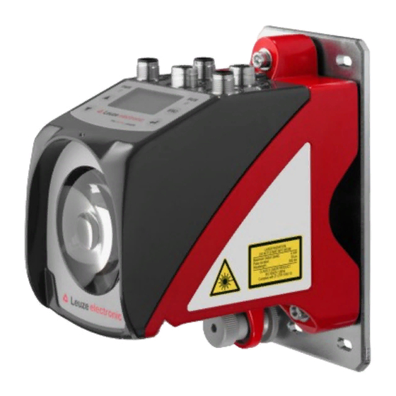
Safety Exemption of liability Leuze electronic GmbH + Co. KG is not liable in the following cases: • The device is not being used properly. • Reasonably foreseeable misuse is not taken into account. • Mounting and electrical connection are not properly performed. - Page 12 A Laser aperture B Laser warning sign C Laser information sign with laser parameters Figure 2.1: Laser apertures, laser warning signs Leuze electronic GmbH + Co. KG AMS 307...
- Page 13 18 μs 18 μs Wavelength: 655 nm 655 nm CLASS 2 LASER PRODUCT IEC 60825-1:2014 Complies with 21 CFR 1040.10 IEC 60825-1:2014 Figure 2.2: Laser warning and information signs – supplied stick-on labels AMS 307 Leuze electronic GmbH + Co. KG...
-
Page 14: Fast Commissioning / Operating Principle
Fast commissioning / operating principle Fast commissioning / operating principle Note! Below you will find a short description for the initial commissioning of the AMS 307i. Detailed explanations for the listed points can be found throughout the handbook. Mounting the AMS 307... -
Page 15: Connecting The Voltage Supply
• Resolution • Error bit on/off For further information, see also Chapter 9 "SSI interface" on page 52 and display menu structure level 2, menu item "SSI" in the appendix of the manual. AMS 307 Leuze electronic GmbH + Co. KG... -
Page 16: Technical Data
50kHz … 800kHz Controls and indicators Keyboard 4 keys Display Monochromatic graphical display, 128 x 64 pixels 2 LEDs, two-colored Inputs/outputs Quantity 2, programmable Input Protected against polarity reversal Output Max. 60 mA, short-circuit-proof Leuze electronic GmbH + Co. KG AMS 307... - Page 17 This is a Class A product. In a domestic environment this product may cause radio interfer- ence, in which case the operator may be required to take adequate measures. The AMS 307 is designed in accordance with protection class III for supply with PELV (protective extra-low voltage). AMS 307 Leuze electronic GmbH + Co. KG...
-
Page 18: Ams 307 Dimensioned Drawing
M5 screw for alignment Knurled nut with WAF4 hexagon socket and M5 nut for securing Optical axis Zero point of the distance to be measured Figure 4.1: AMS 307 dimensioned drawing Leuze electronic GmbH + Co. KG AMS 307... -
Page 19: Overview Of Ams 307 I Types
Overview of AMS 307 types AMS 307 Type designation Description Part no. AMS 307 40m operating range, SSI interface 50137593 AMS 307 120m operating range, SSI interface 50137594 Table 4.1: Overview of AMS 307 types AMS 307 Leuze electronic GmbH + Co. KG... -
Page 20: Installation And Mounting
Note! Please note that the shown name plate is for illustration purposes only; the contents do not correspond to the original. Save the original packaging for later storage or shipping. Leuze electronic GmbH + Co. KG AMS 307... -
Page 21: Mounting The Ams 307 I
AMS 307 and the reflector. Use M5 screws to fasten the laser measurement system. Secure the screws with a lock washer to protect against loosening caused by vibrations. AMS 307 Leuze electronic GmbH + Co. KG... - Page 22 ). Knurled nut and nut must not be tightened until alignment Figure 5.2 has been completed. Attention! The device must not be opened. Failure to comply will render the guarantee void. Warranted features cannot be guaranteed after the device has been opened. Leuze electronic GmbH + Co. KG AMS 307...
-
Page 23: Optional Mounting Bracket
A mounting bracket for mounting the AMS 307 on a flat, horizontal surface is available as an optional accessory. Type designation: MW OMS/AMS 01 Part no.: 50107255 Laser beam Figure 5.3: Optional mounting bracket AMS 307 Leuze electronic GmbH + Co. KG... -
Page 24: Parallel Mounting Of The Ams 307
Both reflectors move in parallel at the same distance to the AMS 307 Measurement distance up to 120m: minimum parallel spacing X ≥ 600mm Leuze electronic GmbH + Co. KG AMS 307... -
Page 25: Parallel Mounting Of Ams 307 I And Ddls Optical Data Transmission
Depending on the size of the used reflector, the DDLS can be mounted with a minimum parallel spacing of 100mm to the AMS 307 . The parallel spacing is independent of the distance. AMS 307 Leuze electronic GmbH + Co. KG... -
Page 26: Mounting The Ams 307 I With Laser Beam Deflector Unit
Use the M5 screws to mount the deflector unit. Secure the screws with a lock washer to protect against loosening caused by vibrations. Figure 5.5: Mounting variants of the US AMS 01 laser beam deflector unit Leuze electronic GmbH + Co. KG AMS 307... -
Page 27: Dimensioned Drawing Of Us Ams 01 Deflector Unit
Installation and mounting 5.3.2 Dimensioned drawing of US AMS 01 deflector unit Laser beam Figure 5.6: Dimensioned drawing of US AMS 01 deflector unit AMS 307 Leuze electronic GmbH + Co. KG... -
Page 28: Mounting The Us 1 Oms Deflector Unit Without Mounting Bracket
Height of the spring in non-preloaded state A Mirror Figure 5.7: Photo and dimensioned drawing of the US 1 OMS deflector unit The laser light spot is aligned with the reflector as described in Chapter 5.2. Leuze electronic GmbH + Co. KG AMS 307... -
Page 29: Reflectors
Reflectors General information The AMS 307 measures distances against a reflective tape specified by Leuze. All technical data given for the AMS 307 , such as the operating range or accuracy, can only be achieved with the reflective tape specified by Leuze. -
Page 30: Technical Data Of Self-Adhesive Tape
Do not use any abrasive agents. A conventional household detergent Cleaning can be used as a cleaning agent. Rinse with clear water and dry the surface. Reflector storage Store in a cool and dry place. Leuze electronic GmbH + Co. KG AMS 307... -
Page 31: Dimensioned Drawing Of Reflective Tape On Carrier Plate
Always align the TOP marking with the AMS connections! (Chapter 6.4.2) Figure 6.1: Dimensioned drawing of reflectors Article Reflective tape (mm) Reflector plate (mm) Reflective tape 200x200-M Reflective tape 500x500-M Reflective tape 914x914-M AMS 307 Leuze electronic GmbH + Co. KG... -
Page 32: Technical Data Of Heated Reflectors
Do not use any abrasive agents. A conventional household Cleaning detergent can be used as a cleaning agent. Rinse with clear water and dry the surface. Reflector storage Store in a cool and dry place. Leuze electronic GmbH + Co. KG AMS 307... -
Page 33: Dimensioned Drawing Of Heated Reflectors
XL ± 1 Si cable 3 x 0.75mm² Figure 6.2: Dimensioned drawing of heated reflectors Article Reflective tape (mm) Insulated carrier plate (mm) Reflective tape 200x200-H Reflective tape 500x500-H Reflective tape 914x914-H AMS 307 Leuze electronic GmbH + Co. KG... -
Page 34: Selecting Reflector Size
Depending on the system design, the reflector can be mounted so that it moves with the vehicle or it can be mounted at a fixed location. Attention! The reflector sizes shown below are a recommendation from Leuze for on-vehicle mounting of the i. For stationary mounting of the... -
Page 35: Mounting The Reflector
For this purpose, use the alignment elements provided on the AMS 307 … (see chapter 5.2 "Mounting the AMS 307i"). If necessary, remove the protective film from the reflector. Attention! The "TOP" label on the reflectors should be aligned the same as the connections of the... - Page 36 Direct reflection due to the triple structure Deflected surface reflection due to the pitch of the reflective tape Figure 6.3: Mounting the reflector Pitch approx. 1° Spacer sleeves Figure 6.4: Pitch of the reflector Leuze electronic GmbH + Co. KG AMS 307...
- Page 37 Direct reflection due to the triple structure Deflected surface reflection due to the pitch of the reflective tape Figure 6.5: Mounting of heated reflectors Pitch approx. 1° Spacer sleeves Figure 6.6: Pitch of the heated reflector AMS 307 Leuze electronic GmbH + Co. KG...
-
Page 38: Table Of Reflector Pitches
Reliable operation of the and, thus, max. operating range and accuracy can only AMS 307 be achieved with the reflective tape specified by Leuze. Correct operation cannot be guar anteed if other reflectors are used! Leuze electronic GmbH + Co. KG... -
Page 39: Electrical Connection
The laser measurement systems are designed in accordance with protection class III for sup ply by PELV (protective extra-low voltage with reliable disconnection). Note! Degree of protection IP65 is achieved only if the connectors and caps are screwed into place! AMS 307 Leuze electronic GmbH + Co. KG... -
Page 40: Pwr - Voltage Supply / Switching Input/Output
+ Clock line SSI CLK+ CLK+ 3 DATA+ (input electrically insulated) - Clock line SSI CLK- (input electrically insulated) CLK- Functional earth M12 connector (B-coded) Thread Functional earth (housing) Table 7.2: SSI pin assignment Leuze electronic GmbH + Co. KG AMS 307... -
Page 41: Service
RS 232 receiving line/ RS232-RX RS232-RX service data M12 socket Not used (A-coded) Thread Functional earth (housing) Table 7.3: Pin assignment - Service Note! The service interface is designed only for use by Leuze! AMS 307 Leuze electronic GmbH + Co. KG... -
Page 42: Display And Control Panel Ams 307 I
Display and control panel AMS 307i Display and control panel AMS 307 Structure of the control panel Status indicator Interface info Bar graph Distance measurement value Control buttons Figure 8.1: Structure of the control panel Status indicators and operation 8.2.1... - Page 43 Display and control panel AMS 307i Plausibility error: Implausible measurement value. Possible causes: light beam interruption, outside of measurement range, permissible internal device temperature considerably exceeded or traverse rate >10m/s. Depending on the configuration, either zero or the last valid measurement value is output at the interfaces.
-
Page 44: Led Status Indicators
Display and control panel AMS 307i 8.2.2 LED status indicators PWR LED Device OFF - No supply voltage Flashing green Power LED flashes green - No measurement value output - Voltage connected - Self test running - Initialization running - Parameter download running... -
Page 45: Control Buttons
Display and control panel AMS 307i Green continuous light BUS LED green - SSI interface is activated Flashing green BUS LED flashes green - SSI interface is being initialized 8.2.3 Control buttons Navigate upward/sideways. Down Navigate downward/sideways. Exit menu item. -
Page 46: Menu Description
Display and control panel AMS 307i Selecting options If options can be selected, the display looks like this: o OFF Default ----------------- Unit Select the desired option with the buttons. Activate the option by pressing Menu description 8.3.1 The main menus After voltage has been applied to the laser, device information is displayed for several seconds. -
Page 47: Parameter Menu
Display and control panel AMS 307i Language selection - main menu Language selection o Deutsch • Selection of the display language. o English See "Language selection menu" on page 48. o Español o Français o Italiano Service - main menu... - Page 48 Display and control panel AMS 307i SSI submenu Table 8.2: SSI submenu Level 3 Level 4 Level 5 Selection/configuration option Standard Description Activation ON/OFF Activates or deactivates the AMS 307 as an SSI participant. Encoding Binary/gray Gray Specifies the output format of the measurement value.
- Page 49 Display and control panel AMS 307i Table 8.3: Position value submenu Level 3 Level 4 Level 5 Selection/configuration option Standard Description Error delay ON/OFF ON/100 Specifies whether, in the event of an error, the position value immediately outputs the value of the "Position value in the case of failure"...
- Page 50 Service Baud rate 57.6kbit/s / 115.2kbit/s 115.2kbit/ RS232 The service interface is only available to Leuze personnel. Format 8,e,1 / 8,n,1 8,n,1 The service interface is only available to Leuze personnel. Leuze electronic GmbH + Co. KG AMS 307...
-
Page 51: Language Selection Menu
Display and control panel AMS 307i 8.3.3 Language selection menu Language selection o Deutsch English o Español o Français o Italiano 5 display languages are available: • German • English • Spanish • French • Italian The AMS 307 is delivered from the factory with the display preset to English. -
Page 52: Operation
Display and control panel AMS 307i Operation An operating process is described here using parameter enable as an example. Parameter enable During normal operation parameters can be viewed only. If parameters are to be changed, the ON menu item in the Parameter -> Parameter handling -> Parameter enable menu must be activated. - Page 53 Display and control panel AMS 307i For the SSI interface, communication between the control and the AMS 307 is also active when parameter enable is active. Note! Changes to the SSI parameters via display entry have immediate effect. Password for parameter enable Parameter entry on the AMS 307 can be protected with a password.
- Page 54 Display and control panel AMS 307i Password Activate password In the Password menu, use the but- Password entry tons to select the Parameter entry menu item. Press the enter button to enter the Password menu. Password entry 0815 Now enter the password (digits).
-
Page 55: Ssi Interface
The SSI interface can only represent positive distance values. If negative output values are ascertained due to the offset or counting direction, a zero value is output at the SSI interface! In the event of a number overflow, all data bits are set to "1". AMS 307 Leuze electronic GmbH + Co. KG... -
Page 56: Ssi Sequence Diagram
1.7ms AMS 307 (default) irrespective of the clock frequency. The update rate on the interface can be reduced to 0.2ms via the display under the SSI menu item. Leuze electronic GmbH + Co. KG AMS 307... -
Page 57: Cable Length Depending On The Data Rate
- Clock line SSI (input electrically insulated) Functional earth Thread Functional earth (housing) Figure 9.2: SSI - electrical connection Note! To connect the SSI interface, we recommend our ready-made SSI cables; see Chapter 11.4.5. AMS 307 Leuze electronic GmbH + Co. KG... -
Page 58: Default Settings Of The Ssi Interface
For basic operation of the display, please refer to Chapter 8.2.3. In order to change the parameters, please activate parameter enable. The SSI interface remains active even during parameter enable. Changes to parameters have an immediate effect. Leuze electronic GmbH + Co. KG AMS 307... -
Page 59: Diagnostics And Troubleshooting
(always "1" because no summation occurs) The status messages within the ring memory are selected with the up/down buttons Use the enter button to call up detailed information about the respective status message: AMS 307 Leuze electronic GmbH + Co. KG... -
Page 60: 10.1.2 Diagnosis
Use the up/down buttons to scroll in the bottom half between various displays. The contents of the scrollable pages are intended solely for Leuze for internal evaluation. The diagnostics have no influence on communication with the host interface and can be acti- vated during operation of the AMS 307 10.1.3 Expanded diagnosis... -
Page 61: General Causes Of Errors
10.3.1 BUS LED Error Possible error cause Measure No supply voltage connected Check supply voltage. BUS LED "OFF" Incorrect wiring Check wiring. SSI deactivated Activate SSI interface in AMS 307 Table 10.2: Bus error AMS 307 Leuze electronic GmbH + Co. KG... -
Page 62: Status Indicators In The Display Of The Ams 307
Send in device at next possible opportunity to have laser diode replaced. Have replace- Laser diode warning ment device ready. Indicates an uncorrectable error in the Send in device for repair. Hardware error hardware Leuze electronic GmbH + Co. KG AMS 307... - Page 63 • Reason for requesting support together with a description For this purpose, please register the merchandise concerned. Simply register return of the merchandise on our website www.leuze.com under Contact & Support -> Repair Service & Returns: To ensure quick and easy processing of your request, we will send you a returns order with the returns address in digital form.
-
Page 64: Type Overview And Accessories
Reflective tape, 200 x 200mm, heated 50115020 200x200-H Reflective tape Reflective tape, 500 x 500mm, heated 50115021 500x500-H Reflective tape Reflective tape, 914 x 914mm, heated 50115022 914x914-H Table 11.2: Overview of reflector types Leuze electronic GmbH + Co. KG AMS 307... -
Page 65: Accessories
11.4.3 Accessories – M12 connector Type designation Description Part no. KD 02-5-BA M12 connector, B-coded socket, SSI 50038538 KD 095-5A M12 connector, A-coded socket, Power (PWR) 50020501 Table 11.5: Accessories – M12 connector AMS 307 Leuze electronic GmbH + Co. KG... -
Page 66: 11.4.4 Accessories - Ready-Made Cables For Voltage Supply
Part no. KD U-M12-5A-V1- M12 socket, A-coded, axial plug outlet, open cable end, 50132079 cable length 5m KD U-M12-5A-V1- M12 socket, A-coded, axial plug outlet, open cable end, 50132080 cable length 10m Leuze electronic GmbH + Co. KG AMS 307... -
Page 67: 11.4.5 Accessories - Ready-Made Cables For The Ssi Interface
Technical data of SSI connection cable Operating temperature range In idle state: -40°C … +80°C In motion: -5°C … +80°C Material Free of halogens, silicone and PVC Bending radius > 80mm, suitable for drag chains AMS 307 Leuze electronic GmbH + Co. KG... - Page 68 KB SSI/IBS-25000-BA M12 socket, B-coded, for SSI/Interbus, axial connector, 50108447 open cable end, cable length 25m KB SSI/IBS-30000-BA M12 socket, B-coded, for SSI/Interbus, axial connector, 50108446 open cable end, cable length 30m Leuze electronic GmbH + Co. KG AMS 307...
-
Page 69: Maintenance
Contact your Leuze distributor or service organization should repairs be required. The addresses can be found on the inside of the cover and on the back. Note! When sending laser measurement systems to Leuze for repair, please provide an accurate description of the fault. 12.3 Disassembling, packing, disposing Repacking For later reuse, the device is to be packed so that it is protected. - Page 70 Parameter handling ....44 General causes of errors ....58 Leuze electronic GmbH + Co. KG AMS 307...
- Page 71 Technical data ..... . . 13 Dimensioned drawing ....15 AMS 307 Leuze electronic GmbH + Co. KG...
- Page 72 Menu structure AMS 307 Level 1 Level 2 Level 3 Level 4 Level 5 Selection/configuration option Detailed infor- mation on : Selection : Selection : Selection : Selection : Selection : Selection : Back : Back : Back : Back : Activate : Back Device information...
- Page 73 Deutsch / English / Español / Français / Italiano Page 48 Service Status messages Number of readings, reading gates, reading rate / non-reading rate etc. Page 48 Diagnosis Only for use by Leuze personnel for service purposes Expanded diagnosis Only for use by Leuze personnel for service purposes...
Need help?
Do you have a question about the AMS 307i and is the answer not in the manual?
Questions and answers