
Related Manuals for Leuze AMS 358i


Summary of Contents for Leuze AMS 358i
- Page 1 AMS 358i Optical laser measurement system – EtherNet/IP Original operating instructions We reserve the right to make technical changes EN 2021/04/30 - 50113351...
- Page 2 © 2021 Leuze electronic GmbH + Co. KG In der Braike 1 D-73277 Owen / Germany Phone: +49 7021 573-0 Fax: +49 7021 573-199 http://www.leuze.com info@leuze.de Leuze electronic GmbH + Co. KG AMS 358...
- Page 3 AMS 358 The main menus Device information - main menu AMS 358i 120 Leuze electronic This menu item contains detailed informa- tion on GmbH & Co. KG • Device type SW: V 1.3.0HW:1 • Manufacturer SN: ----------------------- • Software and hardware version •...
-
Page 4: Table Of Contents
Table of contents General information ..........5 Explanation of symbols . - Page 5 Table of contents Reflectors ........... . . 30 General information .
- Page 6 Table of contents Addressing ............58 9.3.1 Entering the network address via the display .
- Page 7 Table of contents 11.4 Accessories ............104 11.4.1 Accessories –...
-
Page 8: General Information
Note! The Declaration of Conformity for these devices can be requested from the manufacturer. The manufacturer of the product, Leuze electronic GmbH & Co. KG in D-73277 Owen, possesses a certified quality assurance system in accordance with ISO 9001. Leuze electronic GmbH + Co. KG... -
Page 9: Description Of Functions Ams 358 I
With its AMS 3xx product series, Leuze makes available a wide range of internationally rele- vant interfaces. Note that each interface version listed below corresponds to a different AMS 3xx model. -
Page 10: Safety
Leuze electronic GmbH + Co. KG is not liable for damages caused by improper use. Read the technical description before commissioning the device. Knowledge of this ... -
Page 11: Competent Persons
Exemption of liability Leuze electronic GmbH + Co. KG is not liable in the following cases: • The device is not being used properly. • Reasonably foreseeable misuse is not taken into account. -
Page 12: Laser Safety Notices
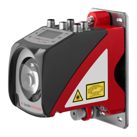
The device must not be tampered with and must not be changed in any way. There are no user-serviceable parts inside the device. Repairs must only be performed by Leuze electronic GmbH + Co. KG. NOTE Affix laser information and warning signs! Laser information and warning signs are attached to the device (see figure 2.1). - Page 13 Safety A Laser aperture B Laser warning sign C Laser information sign with laser parameters Figure 2.1: Laser apertures, laser warning signs AMS 358 Leuze electronic GmbH + Co. KG...
- Page 14 18 μs 18 μs Wavelength: 655 nm 655 nm CLASS 2 LASER PRODUCT IEC 60825-1:2014 Complies with 21 CFR 1040.10 IEC 60825-1:2014 Figure 2.2: Laser warning and information signs – supplied stick-on labels Leuze electronic GmbH + Co. KG AMS 358...
-
Page 15: Fast Commissioning / Operating Principle
Fast commissioning / operating principle Fast commissioning / operating principle Note! Below you will find a short description for the initial commissioning of the AMS 358i. Detailed explanations for the listed points can be found throughout the handbook. Mounting the AMS 358... -
Page 16: Connecting The Voltage Supply
Deactivate parameter enable Configuration of the participant Transferring the data to the control Configuration of the config assembly; when doing so, it is essential to refer to Chapter Using explicit messaging services Leuze electronic GmbH + Co. KG AMS 358... - Page 17 Parameter handling -> Parameter enable Configuring the participant (up to software version 20.00). In the RSLogix 5000 configuration tool for EtherNet/IP, a so-called "generic Ethernet module" is created under the "Communication" path for the AMS 358 AMS 358 Leuze electronic GmbH + Co. KG...
- Page 18 The query cycle of the input and output assemblies is subsequently defined in the "Module properties -> Connection" path in the "Request packet interval (RPI)" input field. The participant is thereby defined in off-line mode; the data must subsequently be transferred to the control. Leuze electronic GmbH + Co. KG AMS 358...
- Page 19 AMS 358 Attention! If parameters are changed via explicit messaging services while simultaneously activating a configuration assembly, the changed parameters must subsequently be entered in the con figuration assembly. AMS 358 Leuze electronic GmbH + Co. KG...
-
Page 20: Technical Data
Position sensor type (absolute encoder) Controls and indicators Keyboard 4 keys Display Monochromatic graphical display, 128 x 64 pixels 4 LEDs, 2 of which are used to indicate the state of the EtherNet/IP connection Leuze electronic GmbH + Co. KG AMS 358... - Page 21 This is a Class A product. In a domestic environment this product may cause radio interference, in which case the operator may be required to take adequate measures. The AMS 358 is designed in accordance with protection class III for supply with PELV (protective extra-low voltage). AMS 358 Leuze electronic GmbH + Co. KG...
-
Page 22: Ams 358 I Dimensioned Drawing
M5 screw for alignment Knurled nut with WAF4 hexagon socket and M5 nut for securing Optical axis Zero point of the distance to be measured Figure 4.1: AMS 358 dimensioned drawing Leuze electronic GmbH + Co. KG AMS 358... -
Page 23: Overview Of Ams 358 I Types
50113730 AMS 358 200 H 200m operating range, EtherNet/IP interface, integrated heating 50113731 AMS 358 300 H 300m operating range, EtherNet/IP interface, integrated heating 50113732 Table 4.1: Overview of AMS 358 types AMS 358 Leuze electronic GmbH + Co. KG... -
Page 24: Installation And Mounting
Note! Please note that the shown name plate is for illustration purposes only; the contents do not correspond to the original. Save the original packaging for later storage or shipping. Leuze electronic GmbH + Co. KG AMS 358... -
Page 25: Mounting The Ams 358 I
AMS 358 and the reflector. Use M5 screws to fasten the laser measurement system. Secure the screws with a lock washer to protect against loosening caused by vibrations. AMS 358 Leuze electronic GmbH + Co. KG... - Page 26 ). Knurled nut and nut must not be tightened until alignment Figure 5.2 has been completed. Attention! The device must not be opened. Failure to comply will render the guarantee void. Warranted features cannot be guaranteed after the device has been opened. Leuze electronic GmbH + Co. KG AMS 358...
-
Page 27: Optional Mounting Bracket
A mounting bracket for mounting the AMS 358 on a flat, horizontal surface is available as an optional accessory. Type designation: MW OMS/AMS 01 Part no.: 50107255 Laser beam Figure 5.3: Optional mounting bracket AMS 358 Leuze electronic GmbH + Co. KG... -
Page 28: Parallel Mounting Of The Ams 358
Measurement distance up to 120m: minimum parallel spacing X ≥ 600mm Measurement distance up to 200m: minimum parallel spacing X ≥ 750mm Measurement distance up to 300m: minimum parallel spacing X ≥ 750mm Leuze electronic GmbH + Co. KG AMS 358... -
Page 29: Parallel Mounting Of Ams 358
Depending on the size of the used reflector, the DDLS can be mounted with a minimum parallel spacing of 100mm to the AMS 358 . The parallel spacing is independent of the distance. AMS 358 Leuze electronic GmbH + Co. KG... -
Page 30: Mounting The Ams 358 I With Laser Beam Deflector Unit
Use the M5 screws to mount the deflector unit. Secure the screws with a lock washer to protect against loosening caused by vibrations. Figure 5.5: Mounting variants of the US AMS 01 laser beam deflector unit Leuze electronic GmbH + Co. KG AMS 358... -
Page 31: Dimensioned Drawing Of Us Ams 01 Deflector Unit
Installation and mounting 5.3.2 Dimensioned drawing of US AMS 01 deflector unit Laser beam Figure 5.6: Dimensioned drawing of US AMS 01 deflector unit AMS 358 Leuze electronic GmbH + Co. KG... -
Page 32: Mounting The Us 1 Oms Deflector Unit Without Mounting Bracket
Height of the spring in non- preloaded state A Mirror Figure 5.7: Photo and dimensioned drawing of the US 1 OMS deflector unit The laser light spot is aligned with the reflector as described in Chapter 5.2. Leuze electronic GmbH + Co. KG AMS 358... -
Page 33: Reflectors
Reflectors General information The AMS 358 measures distances against a reflective tape specified by Leuze. All technical data given for the AMS 358 , such as the operating range or accuracy, can only be achieved with the reflective tape specified by Leuze. -
Page 34: Technical Data Of Self-Adhesive Tape
Do not use any abrasive agents. A conventional household detergent Cleaning can be used as a cleaning agent. Rinse with clear water and dry the surface. Reflector storage Store in a cool and dry place. Leuze electronic GmbH + Co. KG AMS 358... -
Page 35: Dimensioned Drawing Of Reflective Tape On Carrier Plate
Always align the TOP marking with the AMS connections! (Chapter 6.4.2) Figure 6.1: Dimensioned drawing of reflectors Article Reflective tape (mm) Reflector plate (mm) Reflective tape 200x200-M Reflective tape 500x500-M Reflective tape 914x914-M AMS 358 Leuze electronic GmbH + Co. KG... -
Page 36: Technical Data Of Heated Reflectors
Do not use any abrasive agents. A conventional household Cleaning detergent can be used as a cleaning agent. Rinse with clear water and dry the surface. Reflector storage Store in a cool and dry place. Leuze electronic GmbH + Co. KG AMS 358... -
Page 37: Dimensioned Drawing Of Heated Reflectors
XL ± 1 Si cable 3 x 0.75mm² Figure 6.2: Dimensioned drawing of heated reflectors Article Reflective tape (mm) Insulated carrier plate (mm) Reflective tape 200x200-H Reflective tape 500x500-H Reflective tape 914x914-H AMS 358 Leuze electronic GmbH + Co. KG... -
Page 38: Selecting Reflector Size
Depending on the system design, the reflector can be mounted so that it moves with the vehicle or it can be mounted at a fixed location. Attention! The reflector sizes shown below are a recommendation from Leuze for on-vehicle mounting of the i. For stationary mounting of the... -
Page 39: Mounting The Reflector
For this purpose, use the alignment elements provided on the AMS 358 … (see chapter 5.2 "Mounting the AMS 358i"). If necessary, remove the protective film from the reflector. Attention! The "TOP" label on the reflectors should be aligned the same as the connections of the... - Page 40 Direct reflection due to the triple structure Deflected surface reflection due to the pitch of the reflective tape Figure 6.3: Mounting the reflector Pitch approx. 1° Spacer sleeves Figure 6.4: Pitch of the reflector Leuze electronic GmbH + Co. KG AMS 358...
- Page 41 Direct reflection due to the triple structure Deflected surface reflection due to the pitch of the reflective tape Figure 6.5: Mounting of heated reflectors Pitch approx. 1° Spacer sleeves Figure 6.6: Pitch of the heated reflector AMS 358 Leuze electronic GmbH + Co. KG...
-
Page 42: Table Of Reflector Pitches
Reliable operation of the and, thus, max. operating range and accuracy can only AMS 358 be achieved with the reflective tape specified by Leuze. Correct operation cannot be guar anteed if other reflectors are used! Leuze electronic GmbH + Co. KG... -
Page 43: Electrical Connection
The laser measurement systems are designed in accordance with protection class III for sup ply by PELV (protective extra-low voltage with reliable disconnection). Note! Degree of protection IP65 is achieved only if the connectors and caps are screwed into place! AMS 358 Leuze electronic GmbH + Co. KG... -
Page 44: Pwr - Voltage Supply / Switching Input/Output
BUS IN (4-pin socket, D-coded) Name Comment BUS IN Transmit Data + Receive Data + Transmit Data - TD+ 1 Receive Data - Thread Functional earth (housing) M12 socket (D-coded) Table 7.2: BUS IN pin assignment Leuze electronic GmbH + Co. KG AMS 358... -
Page 45: Ethernet/Ip Bus Out
RS232-RX Receiving line RS 232/service data RS232-RX Not used M12 socket (A-coded) Thread Functional earth (housing) Table 7.4: Pin assignment - Service Note! The service interface is designed only for use by Leuze! AMS 358 Leuze electronic GmbH + Co. KG... -
Page 46: Display And Control Panel Ams 358I
Display and control panel AMS 358i Display and control panel AMS 358 Structure of the control panel Status indicator Bus/interface info Bar graph Distance measurement value Control buttons Figure 8.1: Structure of the control panel using the AMS 304 PROFIBUS device variant as... - Page 47 Display and control panel AMS 358i Plausibility error: Implausible measurement value. Possible causes: light beam interruption, outside of measurement range, permissible internal device temperature considerably exceeded or traverse rate >10m/s. Depending on the configuration, either zero or the last valid measurement value is output at the interfaces.
-
Page 48: Led Status Indicators
Display and control panel AMS 358i 8.2.2 LED status indicators After power ON, the Power LED and Net LED are tested as follows: LEDs off. LEDs are switched to green for approx. 0.25s. LEDs are switched to red for approx. 0.25s. - Page 49 Display and control panel AMS 358i Net LED Net LED off - No voltage supply - No IP address assigned (BootP, DHCP) Green, flashing Net LED flashes green - LED function test for 0.25s after power up - no EtherNet/IP communication present...
-
Page 50: Control Buttons
Display and control panel AMS 358i 8.2.3 Control buttons Navigate upward/sideways. Down Navigate downward/sideways. Exit menu item. ENTER Confirm/enter value, change menu levels. Navigating within the menus The menus within a level are selected with the up/down buttons The selected menu item is activated with the enter button Press the ESC button to move up one menu level. -
Page 51: Menu Description
Display and control panel AMS 358i Menu description 8.3.1 The main menus After voltage has been applied to the laser, device information is displayed for several seconds. The display then shows the measurement window with all status information. Device information - main menu... -
Page 52: Parameter Menu
Display and control panel AMS 358i Note! The rear cover of this manual includes a fold-out page with the complete menu structure. It describes the menu items in brief. 8.3.2 Parameter menu Parameter handling submenu The following functions can be called up in the Parameter handling submenu: •... - Page 53 Display and control panel AMS 358i Table 8.2: EtherNet/IP submenu Level 3 Level 4 Level 5 Selection/configuration option Standard Description Gateway The gateway address can be set to any value in the format - --.---.---.---. The AMS 358 communicates with participants in other sub- nets via the gateway.
- Page 54 Display and control panel AMS 358i Table 8.3: Position value submenu Level 3 Level 4 Level 5 Selection/configuration option Standard Description Error delay ON/OFF ON/100 Specifies whether, in the event of an error, the position value immediately outputs the value of the "Position value in the case of failure"...
- Page 55 Service Baud rate 57.6kbit/s / 115.2kbit/s 115.2kbit/ RS232 The service interface is only available to Leuze personnel. Format 8,e,1 / 8,n,1 8,n,1 The service interface is only available to Leuze personnel. AMS 358 Leuze electronic GmbH + Co. KG...
-
Page 56: Language Selection Menu
Display and control panel AMS 358i 8.3.3 Language selection menu Language selection o Deutsch English o Español o Français o Italiano 5 display languages are available: • German • English • Spanish • French • Italian The AMS 358 is delivered from the factory with the display preset to English. -
Page 57: Operation
Display and control panel AMS 358i Operation An operating process is described here using parameter enable as an example. Parameter enable During normal operation parameters can be viewed only. If parameters are to be changed, the ON menu item in the Parameter -> Parameter handling -> Parameter enable menu must be activated. - Page 58 Attention! If the Configuration Assembly function is not activated, parameters set manually via the dis play are activated the moment parameter enabling is again deactivated on the AMS 358i. Note! If a password was stored, parameter enable is not possible until this password is entered;...
-
Page 59: Ethernet/Ip Interface
This significantly increases the data traffic on the network. If the data is to be exchanged only between the AMS and PLC, we recommend that the unicast mode be set at the control for these participants. AMS 358 Leuze electronic GmbH + Co. KG... - Page 60 The AMS 358i communicates via the Common Industrial Protocol (CIP). CIP Safety, CIP Sync and CIP Motion are not supported by the AMS 358i. The EDS file for the AMS 358 can be found on the Leuze homepage www.leuze.com. Leuze electronic GmbH + Co. KG...
-
Page 61: Topology
The display is inverted when parameter enable is active. Attention! The laser measurement system is deactivated on the EtherNet/IP when parameter enable is activated via the display. The device is reactivated on the EtherNet/IP after parameter enable is canceled. AMS 358 Leuze electronic GmbH + Co. KG... -
Page 62: Entering The Network Address Via The Display
To do this proceed as follows: Activate Parameter enable. Select the submenu. EtherNet/IP Select the menu item. IP address Enter the Ethernet IP address and save your entry with save Leuze electronic GmbH + Co. KG AMS 358... - Page 63 Address Gateway Net mask DHCP activated BootP activated Ethernet interface Activation Address Gateway Net mask DHCP activated BootP activated The complete menu structure can be found at the end of the description. AMS 358 Leuze electronic GmbH + Co. KG...
-
Page 64: Ethernet/Ip Device Class
The possibility of integrating the EDS file in the control is not standardized. Check with your control manufacturer whether integration in the control is supported. The EDS file can if required be downloaded from the Leuze homepage www.leuze.com. The data is addressed according to the following fundamental scheme: Device address (IP address) The participant is addressed with its IP address, which is unique in the network. -
Page 65: Ethernet/Ip - Electrical Connection
Functional earth (housing) Figure 9.3: EtherNet/IP - Electrical connection Note! For connecting BUS IN and BUS OUT, we recommend our ready-made Ethernet cables ( chapter 11.4.5 "Accessories - Ready-made cables for EtherNet/IP" AMS 358 Leuze electronic GmbH + Co. KG... -
Page 66: Eds File - General Info
An EDS file (Electronic Data Sheet) is provided for the AMS 358 The EDS file is named "AMS358i.eds"; the corresponding icon is named "AMS358i.ico" Both files can be downloaded at the Leuze homepage www.leuze.com. The EDS file contains all identification and communication parameters of the device, as well as the available objects. -
Page 67: Configuration Steps For A Rockwell Control Without Eds Support
Integrating the hardware into the PLC using the generic Ethernet module In the RSLogix 5000 configuration tool (up to software version 20.00), a so-called generic Ethernet module is created under the Communication path for the AMS 358 Figure 9.4: Generic Ethernet module AMS 358 Leuze electronic GmbH + Co. KG... -
Page 68: Configuration Steps For A Rockwell Control With Eds Support
• First, load the EDS file for the device via EDS wizard into the PLC database. Note! You can find the EDS file at www.leuze.com. • After it has downloaded, select the device from the device list. • Open the input dialog for setting the address and additional parameters by double-click- ing on the device symbol and make the desired entries here. - Page 69 EtherNet/IP interface Figure 9.5: New module • Finally, transmit the values to the control via download. AMS 358 Leuze electronic GmbH + Co. KG...
-
Page 70: Configuration Examples
Figure 9.6: Configuration example 1 - RSLogix 5000 up to software version V19.xx In this configuration, the default settings of the AMS 358 are applied. Input assembly 1 and output assembly 120 are active. Configuration assembly 190 is not active. Leuze electronic GmbH + Co. KG AMS 358... -
Page 71: Example 2 - Rslogix 5000 Up To Software Version V19.Xx
AMS358i in the control. The parameters of all 102 bytes must be copied from the EDS file or manually transferred to the configured configuration assembly 190. AMS 358 Leuze electronic GmbH + Co. KG... -
Page 72: Example 3 - Rslogix 5000 For Software Versions V20.00 And Higher
The RSLogix does, however, only permit the use of one input assembly and/or one output assembly and/or one configuration assembly. Multiple assemblies of type input or output or configuration are not possible. Leuze electronic GmbH + Co. KG AMS 358... -
Page 73: Eds File - Detailed Description
Instance 100, attribute 3 Input assembly: length 8 bytes Leuze-specific assembly Byte 0 - Byte 3: position value Byte 4: AMS 358 status Byte 5: AMS 358 alarms and warnings Byte 6- Byte 7: reserve AMS 358 Leuze electronic GmbH + Co. KG... - Page 74 Bit 3 Bit 2 Bit 1 Bit 0 Position value (low byte) Position value Position value Position value (high byte) Velocity value (low byte) Velocity value Velocity value Velocity value (high byte) Leuze electronic GmbH + Co. KG AMS 358...
- Page 75 1 = ON 1 = ON 1 = ON 0 = OFF 0 = OFF 0 = OFF 0 = OFF 0 = OFF Note! Negative values are shown in two's complement. AMS 358 Leuze electronic GmbH + Co. KG...
- Page 76 Preset value Preset value Preset value (high byte) Preset Preset reset teach 1 = ON 1 = ON 0 = OFF 0 = OFF Note! Negative values are shown in two's complement. Leuze electronic GmbH + Co. KG AMS 358...
- Page 77 Only parameters that are also entered in the configuration assembly can be taken into con sideration in all operating situations of the AMS 358i. Parameters that are set by means of explicit calls, but not entered in the configuration assembly may therefore only have a tem porary effect.
- Page 78 Limit value range start High byte 0 0 0 0 0 0 0 0 105 / 2 / 7 Limit value range end Low byte 0 0 0 0 0 0 0 0 Leuze electronic GmbH + Co. KG AMS 358...
- Page 79 Example: Position value format metric = Velocity format value metric Differing formats, e.g. position value metric and velocity value inch, are not allowed. AMS 358 Leuze electronic GmbH + Co. KG...
-
Page 80: Class 1 Identity Object
Leuze as an encoder. According to ODVA, the AMS 358 assigned number 34 = 22 9.10.2.3 Product Code The product code is an ID assigned by Leuze that has no further impact on other objects. 9.10.2.4 Revision Version number of the identity object. 9.10.2.5 Status Basic and higher-level monitoring of the device, network and configuration. - Page 81 . The default entry 0 (zero) does not change. 9.10.2.10Heartbeat interval The attribute sets a time interval in which a "heartbeat message" is sent by the AMS 358 The value is specified in seconds. AMS 358 Leuze electronic GmbH + Co. KG...
-
Page 82: Class 35 Position Sensor Object
From this address range, the AMS 358 uses only attributes that are func- tionally mapped in the AMS. The address range ≥ 100 is manufacturer-specific. 9.10.3.1 Position Value Attribute 10 Reading out position value. Leuze electronic GmbH + Co. KG AMS 358... - Page 83 If the position format is changed from inch to metric, the velocity format is internally changed automatically to millimeters per second. 9.10.3.5 Velocity value Attribute 24 Reading out velocity value. AMS 358 Leuze electronic GmbH + Co. KG...
- Page 84 Attribute 26 The free resolution refers to parameters 2068 and 2069 in attribute 25 (Velocity format). The entry is made in mm/100 s for parameter 2068 and in inch/1000 s for parameter 2069. Leuze electronic GmbH + Co. KG AMS 358...
- Page 85 Bit 0 = 1; PLB alarm is supported by the AMS 358 Bit 1 = 1; ERR alarm is supported by the AMS 358 Bit 2 to bit 15 = 0 Bit 13 = 1 (VME; velocity / velocity) AMS 358 Leuze electronic GmbH + Co. KG...
- Page 86 Bit 15 = 1; ATT warning is supported by the AMS 358 Bit 0 to bit 12 = 0 9.10.3.14Warning flag Attribute 49 The attribute evaluates the warnings supported in attribute 48, in an OR function (collective warning). Leuze electronic GmbH + Co. KG AMS 358...
- Page 87 The attribute indicates whether the preset function is activated. 1 = Preset active 0 = Preset inactive 9.10.3.19Preset toggle Attribute 103 The attribute is toggled after activation of the preset value. Note! Activation of the preset value via attribute 101. AMS 358 Leuze electronic GmbH + Co. KG...
- Page 88 Measurement value at the interface = measured distance + offset. The attribute sets an offset relative to the measured value in the AMS 358 . The offset is immediately effective after the instruction "set attribute single class1 instance1 attribut108". Leuze electronic GmbH + Co. KG AMS 358...
-
Page 89: Class 100 Display Configuration
Data Access Designation Size Default Min. Max. type in bit (dec) (dec) (dec) Inst. Attr. Language selection BYTE Password protection BYTE Password UINT 9,999 Illumination BYTE Contrast BYTE Extended heating BYTE control AMS 358 Leuze electronic GmbH + Co. KG... - Page 90 0 = Display illumination switches off 10 minutes after a button was last pressed 1 = Display illumination is always on 9.10.4.5 Contrast The display contrast can change under extreme ambient temperatures. This attribute adjusts the display illumination. Value Contrast Weak Medium Strong Leuze electronic GmbH + Co. KG AMS 358...
-
Page 91: Class 103 Switching Inputs / Outputs
WORD Input function BYTE Status (input/output) BYTE Output activation BYTE Function of I/O (input/ BYTE output) Activation (high-active/ BYTE low-active) Output function WORD Input function BYTE Status (input/output) BYTE Output activation BYTE AMS 358 Leuze electronic GmbH + Co. KG... - Page 92 The switching input reacts to the edge set in attribute 2. The laser is switched OFF if the switching input detects an edge change as described in attribute 2. If an opposing edge is detected at the switching input, the laser is switched ON again. Leuze electronic GmbH + Co. KG AMS 358...
- Page 93 / 0000 0000 0011 1000 is specified. This means that an edge change, as defined in attribute 2, takes place at the output (PIN 4) if the LSR or TMP or ATT message occurs. AMS 358 Leuze electronic GmbH + Co. KG...
-
Page 94: Class 104 Error Handling Procedures
Error delay (position) BYTE Error delay time (posi- UINT 1,000 tion) Velocity in the case of BYTE failure Suppress velocity sta- BYTE Error delay (velocity) BYTE Error delay time UINT 1,000 (velocity) Leuze electronic GmbH + Co. KG AMS 358... - Page 95 Attribute 5 The attribute specifies which velocity is transferred, in the event of an error, after the "Velocity error delay time" has elapsed. 0 = Last valid value 1 = Value 0 AMS 358 Leuze electronic GmbH + Co. KG...
-
Page 96: Class 105 Velocity Monitoring
Class 105, instance 2: attributes for velocity limit value 2 Class 105, instance 3: attributes for velocity limit value 3 Class 105, instance 4: attributes for velocity limit value 4 Object class 105 = 69 Service: • Get_Attribute_Single • Set_Attribute_Single Leuze electronic GmbH + Co. KG AMS 358... - Page 97 BYTE The described attributes each apply to instances 1 - 4 9.10.7.1 Velocity limit value - Release Attribute 1 The attribute activates the respective velocity monitoring. 0 = Inactive 1 = Active AMS 358 Leuze electronic GmbH + Co. KG...
- Page 98 The limit value is monitored beginning at this position. The value is specified in mm or inch/ 100. If the values for range start and range end are identical, velocity monitoring is active over the entire traversing range. Leuze electronic GmbH + Co. KG AMS 358...
- Page 99 9.10.7.9 Velocity limit value - Limit value comparison Attribute 9 The attribute indicates whether the respective velocity limit value is compared with the config- ured limit value. 0 = Comparison not active 1 = Comparison active AMS 358 Leuze electronic GmbH + Co. KG...
-
Page 100: Diagnostics And Troubleshooting
(always "1" because no summation occurs) The status messages within the ring memory are selected with the up/down buttons Use the enter button to call up detailed information about the respective status message: Leuze electronic GmbH + Co. KG AMS 358... -
Page 101: Diagnosis
Use the up/down buttons to scroll in the bottom half between various displays. The contents of the scrollable pages are intended solely for Leuze for internal evaluation. The diagnostics have no influence on communication with the host interface and can be acti- vated during operation of the AMS 358 10.1.3 Expanded diagnosis... -
Page 102: General Causes Of Errors
10.2.1 Power LED See also Chapter 8.2.2. Error Possible error cause Measure No supply voltage connected Check supply voltage. PWR LED "OFF" Hardware error Send in device. Table 10.1: General causes of errors Leuze electronic GmbH + Co. KG AMS 358... - Page 103 Plausibility error Traverse rate >10m/s. Hardware error For error description, see display, PWR LED "static red" It may be necessary to send in the device. Table 10.1: General causes of errors AMS 358 Leuze electronic GmbH + Co. KG...
-
Page 104: Interface Errors
Check configuration in the control. The AMS 358 is not listed in the scan list of green" the master The AMS 358i is not assigned to a master Check configuration in the control. Net LED "flashes No EtherNet/IP communication present green/red"... - Page 105 • Reason for requesting support together with a description For this purpose, please register the merchandise concerned. Simply register return of the merchandise on our website www.leuze.com under Contact & Support -> Repair Service & Returns: To ensure quick and easy processing of your request, we will send you a returns order with the returns address in digital form.
-
Page 106: Type Overview And Accessories
50113730 AMS 358 200 H 200m operating range, EtherNet/IP interface, integrated heating 50113731 AMS 358 300 H 300m operating range, EtherNet/IP interface, integrated heating 50113732 Table 11.1: Overview of AMS 358 types Leuze electronic GmbH + Co. KG AMS 358... -
Page 107: Overview Of Reflector Types
Deflector unit without mounting bracket for simple 90° deflection of 50035630 laser beam Table 11.4: Accessories – Deflector unit 11.4.3 Accessories – M12 connector Type designation Description Part no. Table 11.5: Accessories – M12 connector AMS 358 Leuze electronic GmbH + Co. KG... -
Page 108: Accessories - Ready-Made Cables For Voltage Supply
Part no. K-D M12A-5P-5m- M12 socket, A-coded, axial connector outlet, open cable end, 50104557 cable length 5m K-D M12A-5P-10m- M12 socket, A-coded, axial connector outlet, open cable end, 50104559 cable length 10m Leuze electronic GmbH + Co. KG AMS 358... -
Page 109: Accessories - Ready-Made Cables For Ethernet/Ip
Cable designation: KB ET - … - SA Accessory M12 EtherNet/IP connection cable with both-sided D-coded M12 connector Cable designation: KB ET - … - SSA Accessory EtherNet/IP connection cable, M12-/RJ45 Cable designation: KB ET - … - SA-RJ45 AMS 358 Leuze electronic GmbH + Co. KG... - Page 110 Cable length 15m 50106902 KB ET - 20000 - SSA Cable length 20m 50106903 KB ET - 25000 - SSA Cable length 25m 50106904 KB ET - 30000 - SSA Cable length 30m 50106905 Leuze electronic GmbH + Co. KG AMS 358...
-
Page 111: Maintenance
Contact your Leuze distributor or service organization should repairs be required. The addresses can be found on the inside of the cover and on the back. Note! When sending laser measurement systems to Leuze for repair, please provide an accurate description of the fault. 12.3 Disassembling, packing, disposing Repacking For later reuse, the device is to be packed so that it is protected. - Page 112 Interface info in display ....44 Internal hardware error ....44 Leuze electronic GmbH + Co. KG AMS 358...
- Page 113 Parameter enable ....54 Parameter menu EtherNet/IP ..... . . 49 AMS 358 Leuze electronic GmbH + Co. KG...
- Page 114 Velocity in the case of failure ... . 92 Velocity limit value Direction selection ....95 Leuze electronic GmbH + Co. KG AMS 358...
- Page 115 Menu structure AMS 358 Level 1 Level 2 Level 3 Level 4 Level 5 Selection/configuration option Detailed infor- mation on : Selection : Selection : Selection : Selection : Selection : Selection : Back : Back : Back : Back : Activate : Back Device information...
- Page 116 Deutsch / English / Español / Français / Italiano Page 53 Service Status messages Number of readings, reading gates, reading rate / non-reading rate etc. Page 53 Diagnosis Only for use by Leuze personnel for service purposes Expanded diagnosis Only for use by Leuze personnel for service purposes...
Need help?
Do you have a question about the AMS 358i and is the answer not in the manual?
Questions and answers